


- Transient response of layered and multiphase piezo electric/magnetic beams subjected to thermal loading
Dhanasekaran Rajagopala,*, A. Kumaravelb, D. Senthilkumarc, P. Balashreeb, V. Maruthamuthub and S. Mirdhunb
aDepartment of Mechanical Engineering, Adhiyamaan College of Engineering, Hosur, Tamil Nadu – 635109, India
bDepartment of Mechanical Engineering, K.S.Rangasamy College of Technology, Tiruchengode, Tamil Nadu – 637215, India
cDepartment of Mechanical Engineering, Sona College of Technology, Salem, Tamil Nadu – 636005, IndiaThis article is an open access article distributed under the terms of the Creative Commons Attribution Non-Commercial License (http://creativecommons.org/licenses/by-nc/4.0) which permits unrestricted non-commercial use, distribution, and reproduction in any medium, provided the original work is properly cited.
The study investigates the transient response of a cantilever Magneto-Electro-Elastic (MEE) beam subjected to thermal loading. A finite element model utilizing an eight-node quadrilateral element was developed using a FORTRAN program to integrate mechanical, electrical, and magnetic fields. This model was employed to examine the influence of stacking sequences in layered beams and volume fractions in multiphase MEE beams. To validate the accuracy of the developed model, results were compared with those from the commercial finite element software ANSYS, using a beam composed of piezoelectric ceramic material. The comparison confirmed a strong correlation between the results, ensuring the model’s reliability. Findings reveal that piezoelectric coupling significantly affects the mechanical response, while the dynamic responses of electrical and magnetic fields demonstrate complex dependencies on stacking sequences and volume fractions. These insights are crucial for understanding the dynamic behavior of layered and multiphase MEE ceramic materials, which hold great potential for application as sensors or actuators in active structural systems.
Keywords: Piezoelectric cantilever beam, Magneto-Electro-Elastic materials, Transient thermo-elastic analysis, Mechanical response.
Magneto-electro-elastic (MEE) materials exhibit significant coupling effects between various physical fields, such as electric, magnetic, and mechanical fields [1-4]. Due to exceptional coupling effects, MEE materials have found widespread applications in diverse fields, including sensors, actuators, transducers, and energy harvesting devices [5-13]. The integration of MEE materials can facilitate the development of innovative smart composites alongside traditional structural materials [14-17]. The transient response of a specialized non-homogeneous MEE hollow cylinder subjected to sudden constant pressure and dynamic combined loads is investigated by Hou et al. [18]. A thermodynamic potential has been employed to derive the linear constitutive equations for thermo-piezo-magnetism [19, 20]. These equations are relevant in linear regimes encompassing thermal, magnetic, electrical, and mechanical fields. The effect of piezoelectric and magnetic constants on displacement, electric potential, and magnetic potential across the thickness direction of a magneto-electro-elastic (MEE) beam in a temperature environment is examined using a steady-state approach [10]. By utilizing a variational approach, the general coupled field finite element equations that describe the dynamic behavior of the thermo-piezo-magnetic medium have been derived. Similarly, Jiang and Ding [21] used stringent differential operator theorems to provide analytical solutions based on the two-dimensional fundamental equations of transversely isotropic magneto-electro-elastic media. They successfully derived distinct eigenvalues expressed through four harmonic displacement functions, incorporating mechanical, electrical, and magnetic quantities.
Additionally, an accurate solution for the transient response of a multilayered, simply supported magneto-electro-thermoelastic strip under nonuniform heat input was investigated by Ootao and Tanigawa [22]. Analytical procedure on a simply supported three-layered BaTiO3-CoFe2O4 composite strip reveals transient behaviors in temperature, displacement, stress, and electric/magnetic potentials, extendable to arbitrary multilayered configurations. The plane stress problem for linear, anisotropic, functionally graded magneto-electro-elastic plane beams, in which material properties vary arbitrarily in the thickness direction, was also examined by Huang et al. [23]. For situations such as tension, pure bending, cantilever beams with shear force at the free end, and cantilever beams under uniform load, they provided analytical answers. It has been investigated how to solve simply supported multilayered plates with linear magneto-electro-elastic characteristics under surface and in-plane stresses [24]. The researcher employed the propagator matrix method to achieve precise and efficient results for multilayered configurations. Findings indicate that the response to internal loading varies significantly from that of surface loading, particularly in relatively thin plates. Additionally, the stacking sequences play a crucial role in influencing most physical properties, especially electrical and magnetic characteristics. A hybrid method of solid mechanics was used to obtain the state vector equations for magneto-electro-elastic materials [25, 26]. This method views stresses, electric displacements, and magnetic inductions as fundamental unknowns in addition to displacements, electric potential, and magnetic potential. Numerical results for rectangular plates with simply supported multi-layered structures under surface loading were given. Moreover, the precise solution for multi-layered rectangular functionally graded linear MEE plates was obtained by Pan and Han [24]. The pseudo-Stroh formalism is used to find a homogeneous solution, assuming that the functionally graded material varies exponentially in the thickness direction. Their research examines how the induced magneto-electro-elastic fields are affected by the exponential factor, magneto-electro-elastic characteristics, and loading kinds. Ye et al. [27] applied the Scaled Boundary Finite Element Method (SBFEM) is a semi-analytical numerical technique that combines the advantages of both the Finite Element Method (FEM) and the Boundary Element Method (BEM) to analyze free vibration and transient dynamics of composite magneto-electro-elastic (MEE) cylindrical shells. Using SBFEM simplifies discretization, avoids transverse shear locking, and ensures accurate results. Numerical validation confirms excellent agreement with published solutions and ANSYS simulations, demonstrating practical applicability. Biju et al. [28] investigated the the dynamic response of a magneto-electro-elastic sensor bonded to a cylindrical shell using a semi-analytical finite element method. The response to internal pressure is analyzed for clamped-free and clamped-clamped conditions. Results show maximum response at the clamped end, with better load history replication at the free end than the middle. Zhou et al. [29] studied to improve accuracy in transient response simulations of magneto-electro-elastic structures, a cell-based smoothed finite element model is introduced. By incorporating gradient smoothing, this method reduces numerical errors, achieves near-exact stiffness, and enhances element discretization. It is applied to sensors, energy harvesters, and smart devices, outperforming standard finite element models. Dhanasekaran et al. [30] investigated the behavior of mild steel beams with multiphase magneto-electro-elastic, piezoelectric, or magnetostrictive patches under temperature variations. The finite element method was used to analyze electric and magnetic potentials, considering coupling effects. The findings offer insights into the behavior of such structures under varying temperature conditions. Dai and Wang [31] studied the analytical solution to magneto–thermo–electro–elastic problems in a piezoelectric hollow cylinder subjected to various transient loads. This solution involves solving the Volterra integral equation of the second kind to determine the electric displacement, and employs Hankel and Laplace transforms to derive exact expressions for transient responses. The methodology is validated through numerical calculations, demonstrating its applicability to complex coupled problems in magneto–thermo–electro–elasticity. A dependent variable and a special function are introduced to satisfy inhomogeneous mechanical boundary conditions, transforming the governing equation into a homogeneous form. Using separation of variables and boundary conditions, the problem is reduced to Volterra integral equations. Cubic Hermite polynomials approximate solutions, determining transient responses of displacement, stress, and potentials [32, 33]. Zhou et al. [34] examined the transient magnetoelectric (ME) response of a symmetric Terfenol-D/PZT/Terfenol-D laminate structure under transient currents. Time-domain output voltages were analyzed for square, sine, and triangle transient voltages. Damping oscillations at the natural frequency were observed with fast-changing currents, weakening when the transient current width matched the laminate’s natural period. Bodaghi and Shakeri [35] analytically examined the free vibration and dynamic response of simply supported functionally graded piezoelectric cylindrical panels under time-dependent blast pulses. Equations of motion are derived using Hamilton’s principle and the first-order shear deformation theory, incorporating Maxwell’s equations.
But according to the literature review, finite element method has been addressed with limited researchers to investigate the transient response of a magneto-electro-elastic beam exposed to a temperature environment. Building on this foundation, the current study examines the transient response of mechanical, electrical, and magnetic fields in layered and multiphase MEE cantilever beams subjected to thermal loading. The constitutive model proposed by Sunar et al. [19] is employed for this analysis. Two stacking sequences are considered for the layered beam: B/F/B (BaTiO3/CoFe2O4/BaTiO3) and F/B/F (CoFe2O4/BaTiO3/CoFe2O4). The volume percentage of BaTiO3 in the multiphase MEE beam is varied in increments of 20%, from 0% to 100%.
Without body force, free charge, free current density, or an internal heat source, the generalized governing differential equations for magneto-electro-thermoelastic issues can be expressed as follows:

Where T0 denotes the reference temperature and the ρ mass density. The constitutive equation for a three-dimensional solid that is linearly magneto-electro-elastic with thermal effects can be formulated using a Cartesian coordinate system (x3) [19],
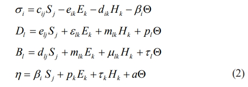
where i, j = 1,...., 6 and i, j = 1,...., 3. η, Bl, Dl and σi represent the components of entropy per unit volume, magnetic induction, electric displacement, and stress, respectively. μik, εik and cij are the coefficients of magnetic permeability, dielectric, and elastic, respectively. mik, dik and eik are magneto-electric, piezomagnetic and piezoelectric material coefficients respectively. Q, tl, pl and βi are the temperature difference, pyromagnetic constant, pyroelectric constant, and stress temperature coefficient, respectively. Ek, Hk and Sj are vectors for the electric field, magnetic field, and linear strain tensor, respectively. α=ρCE, CE is the specific heat of the material. Q = T - T0, is the absolute temperature and T0 is the reference temperature. The coupled three-dimensional constitutive Eq. (2) for a magneto-electro-elastic solid in the plane is taken to be isotropic for the present analysis. Where σ1 = σx1, σ2 = σx2,σ3 = σx3, σ4 = tx2x3, σ5 = tx1x3, σ6 = tx1x2, D1 = Dx1, D2 = Dx2, D3 = Dx3, B1 = Bx1, B2 = Bx2 and B3 = Bx3.
Finite element formulation
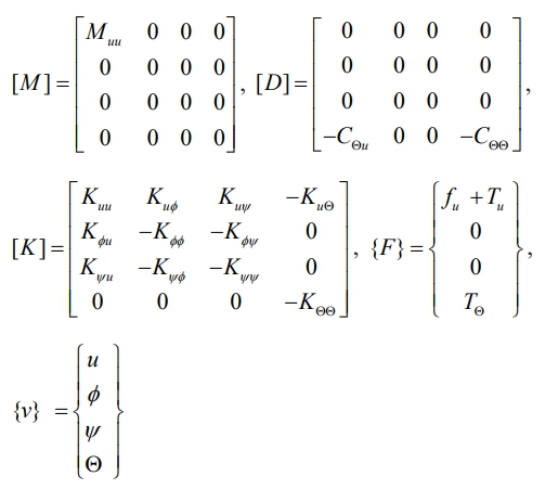
An eight-node quadratic element is used to model a MEE beam. The typical finite element mesh of the eight-node quadrilateral element and MEE cantilever beam is shown in Fig. 1.
Temperature (Q), axial displacement (u1), transverse displacement (u3), electric potential (Φ), and magnetic potential (Ψ) are the five degrees of freedom that each node possesses. The elemental degrees of freedom (d.o.f.) arrays are as follows: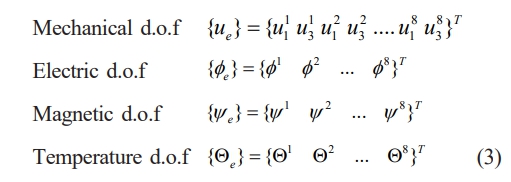
Eq. (4) provides the corresponding nodal quantities. The displacements ({u}={u1 u3}T), electric potential (Φ), magnetic potential (Ψ), and temperature (Q) within the element can all be represented in terms of element shape functions.
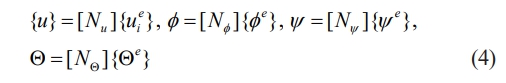
where
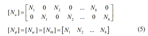
N1,N2 ,..., N8 are shape functions.
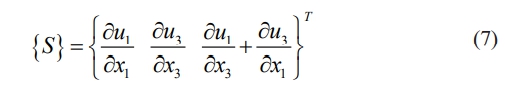
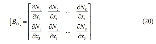
For plane stress problems, consider magnetic induction B2 = 0, electric displacement D2 = 0, and stress components σ2 = σ4 = σ6 = 0. One way to express the strain displacement relation is,
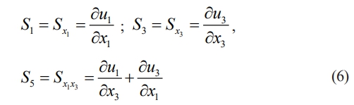
The array of strain-displacement relation is given by,
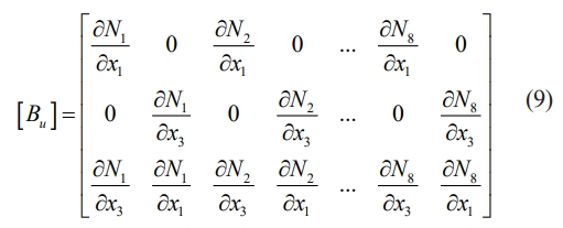
The following expression (Eq. (8)) can be used to connect the strains to the nodal degree of freedom:

Where [Bu] is the relationship between strain - displacement.
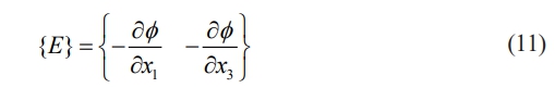
The relationship between electric field and electric potential can be written as,
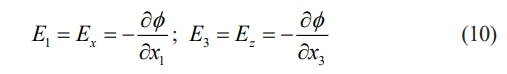
The electric field vector array is provided by
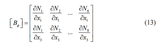
The following expression can be used to connect the electric field vector to the electric potential as a nodal degree of freedom.

The matrix [Bf], referred to as the electric field–electric potential matrix, is constructed as given below
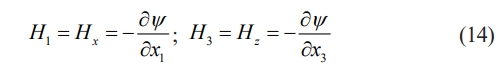
The relationship between magnetic field and magnetic potential is as follows:
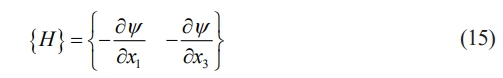
The magnetic field vector array is given by
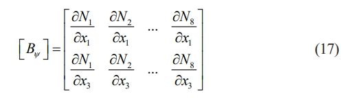
The magnetic field vector can be expressed as a nodal degree of freedom in relation to the magnetic potential using the following equation:
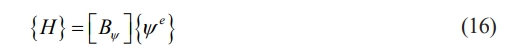
The magnetic field-magnetic potential matrix [By] is written as
The temperature gradient is as follows
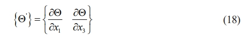
The following statement can be used to relate the temperature gradient to the temperature field as a nodal degree of freedom.
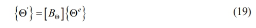
The temperature gradient-temperature difference matrix [BQ] is written as
The reduced coefficients for plane stress problems are derived in terms of material constants. Reduced coefficients replace the coefficients m͞͞lk. The various reduced coefficient matrices derived for the plane stress problem are given. Considering the body force { f }, the virtual displacement principle can be written [15, 33]
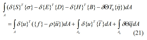
where the sign for variance is δ. Eqs. (8), (12), (16), (19), and (2) allow an expansion of each term in the virtual work expression as
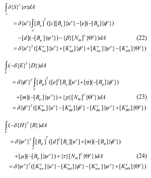
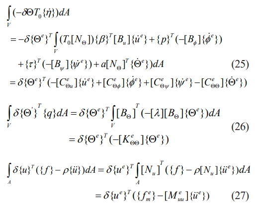
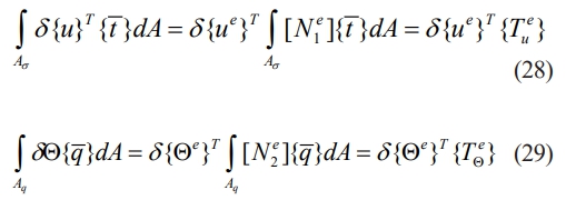
The following matrix form can be used to explain the equation above.
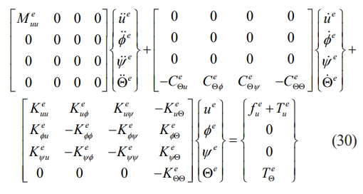
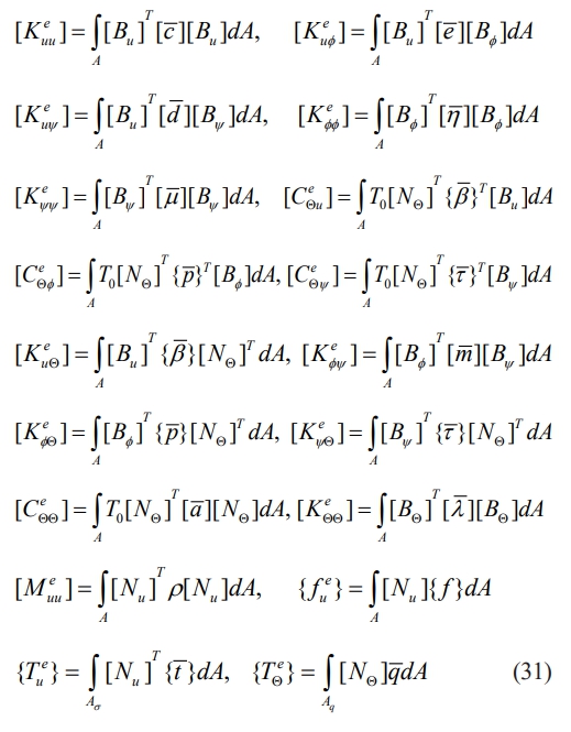
where the Eq. (30) defines the various elemental matrices as
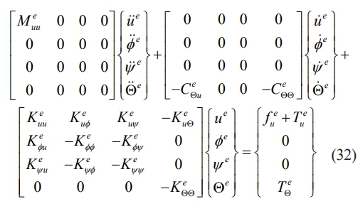
In this study, the pyroelectric and pyromagnetic constants are excluded for magneto-electro-elastic materials. Therefore, Eq. (30) can be expressed as
When all element contributions are combined from Eq. (32), the equation of motion can be expressed as
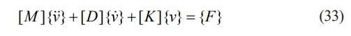
where
The Newmark b technique is used to solve Eq. (33) for the transient response of displacement, electric potential, and magnetic potential.
Validation
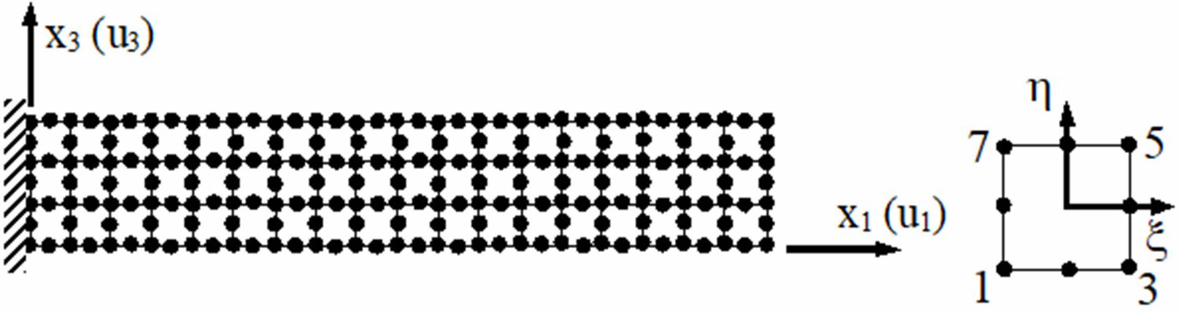
The commercial finite element program ANSYS is used to evaluate the current formulation for examining the thermo-elastic behavior of a piezoelectric cantilever beam. Fig. 2 illustrates the schematic of the piezo-thermo-elastic cantilever beam, which has a length of 1m and a thickness of 0.006 m and is subjected to a transient thermal gradient of 20 °C.
The finite element model used in the FORTRAN Programming, which was created for magneto-electro-thermo-elastic analysis utilizing only temperature and displacement nodal degrees of freedom, is seen in Fig. 1. A four-node PLANE13 quadrilateral coupled field element with three degrees of freedom per node—axial displacement, transverse displacement, and temperature—is used to represent the thermo-elastic cantilever beam in ANSYS. For this analysis, a mesh size of 30 × 6 is chosen following a convergence study.
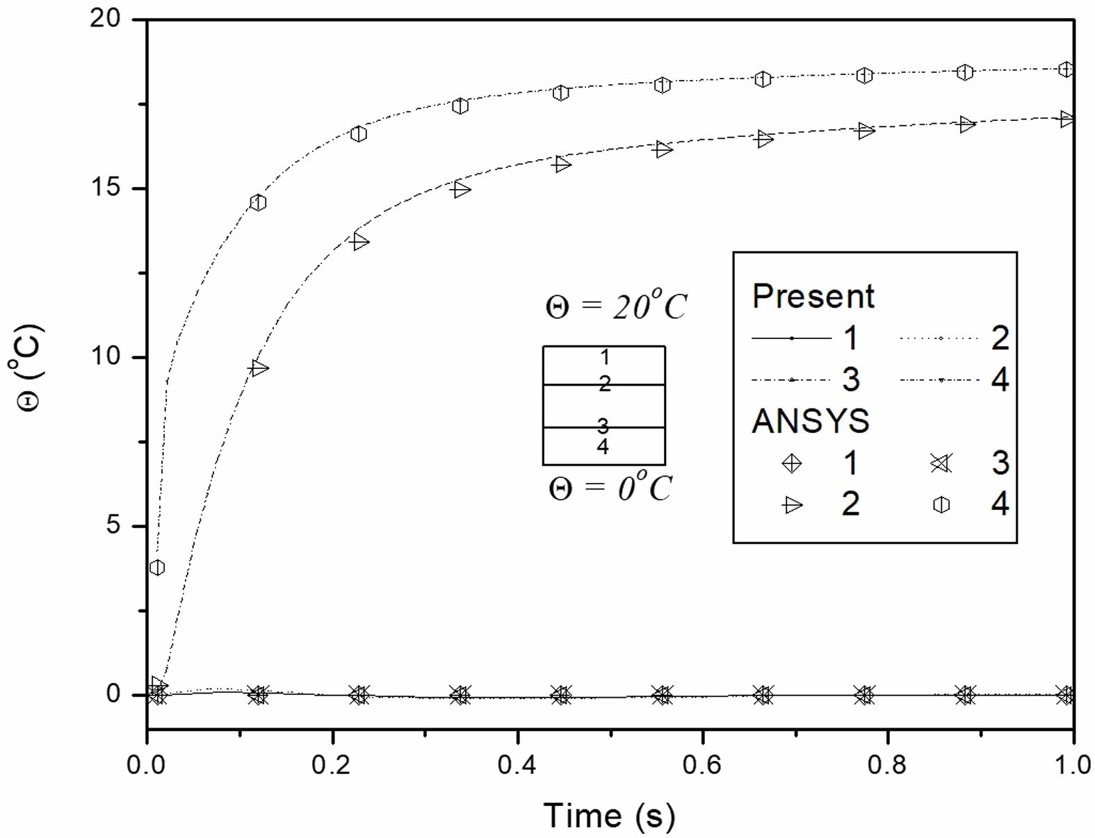
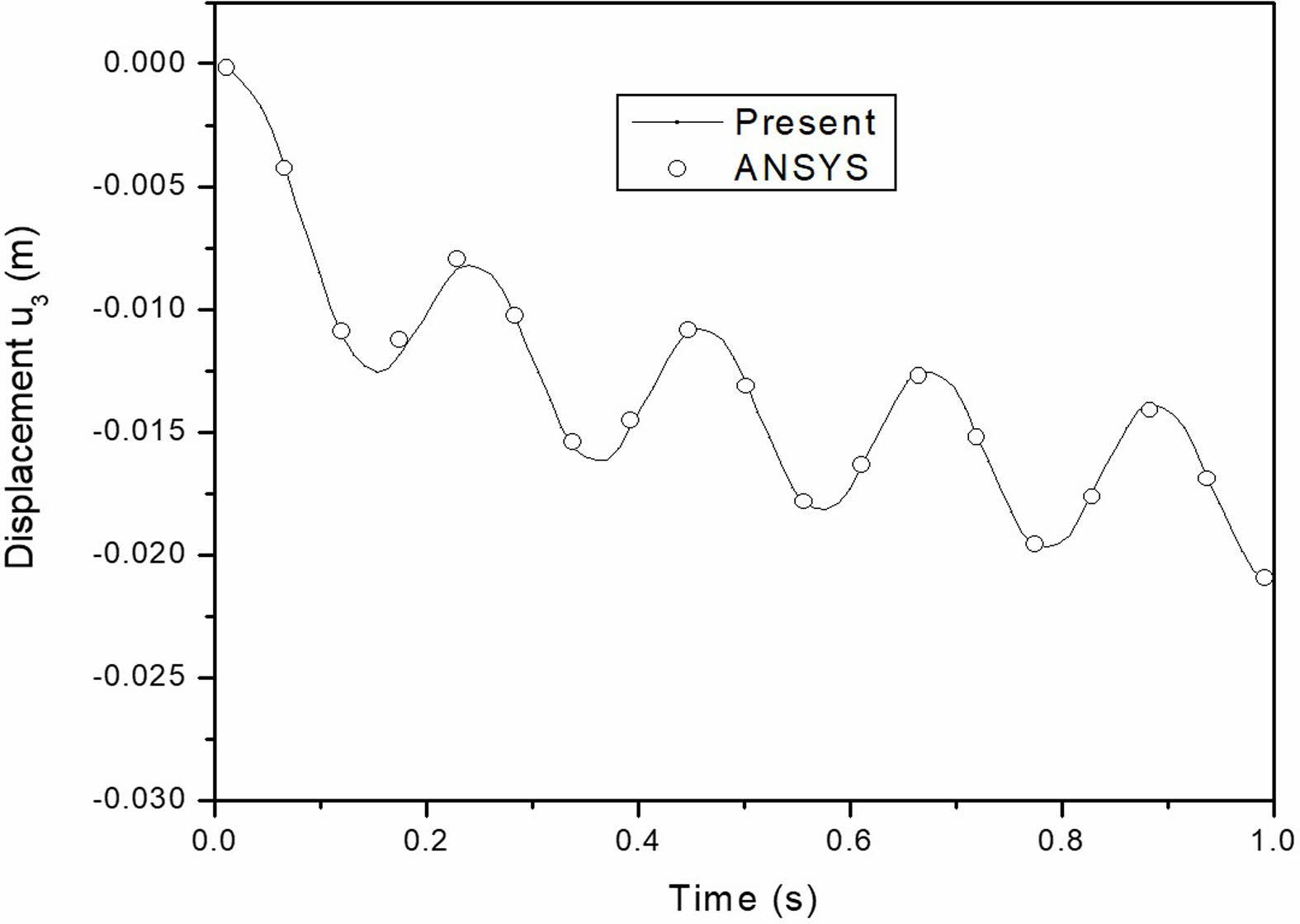
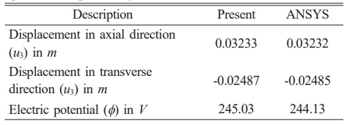
The temperature distribution and thermally induced vibrations of the elastic beam, related to the stiffness coefficient of the piezoelectric material, are validated against ANSYS results. The results for 1s are shown in Fig. 3, depicting temperature buildup across the thickness in close alignment with ANSYS outcomes. Fig. 4 illustrates the thermally induced vibration of the cantilever beam under transient thermal loading, also showing close agreement with ANSYS results. To confirm the accuracy of the piezoelectric component, a static analysis under steady-state temperature distribution was carried out because ANSYS does not provide transient piezo-thermo-elastic analysis. At the cantilever beam’s fixed end, there is no electric potential. The greatest electric potential created in the piezoelectric cantilever beam, along with the axial and transverse displacements at the free end, are compared in Table 1. The findings indicate that ANSYS and the current study accord well.
The FORTRAN Program has been independently validated for transient thermo-elastic investigations and the coupling of piezo terms using the two validation studies mentioned above.
|
Fig. 1 Cantilever beam discretization using finite elements and an eight-node quadrilateral element. |
|
Fig. 2 Schematic model of cantilever piezoelectric beam. |
|
Fig. 3 Comparison of temperature build-up across the thickness direction. |
|
Fig. 4 Comparison of mechanical response of cantilever thermoelastic beam. |
|
Table 1 Comparison of displacement at free end and maximum electric potential of a piezoelectric cantilever beam under specified temperature gradient. |
The temperature, mechanical, electric, and magnetic responses of multiphase and multilayer MEE beams to transient thermal loading are considered for the present study. The physical layout of a stacked MEE beam is depicted in Fig. 1. The material properties and thermal properties are used from existing literature [30]. The dimensions of the beam are: length (l) = 1 m, thickness (t) = 0.006 m. In the present study, a 30 × 6 mesh size is chosen. At the cantilever beam’s fixed edge, both the electric and magnetic potentials are zero (Φ=φ=0).
Fig. 2 displays the thermal boundary conditions. Eight noded plane stress elements are used to model the layered and multiphase MEE beam. The B/F/B and F/B/F stacking sequences of a multilayer MEE beam are taken into consideration. Various volume fractions of BaTiO3 in the BaTiO3-CoFe2O4 composite make up the multiphase MEE beam. For the study, the volume fractions 0.0, 0.2, 0.4, 0.6, 0.8, and 1.0 are taken into account. A study on multiphase and multilayer MEE cantilever beams is carried out. For 2s, the results are plotted.
Temperature Response
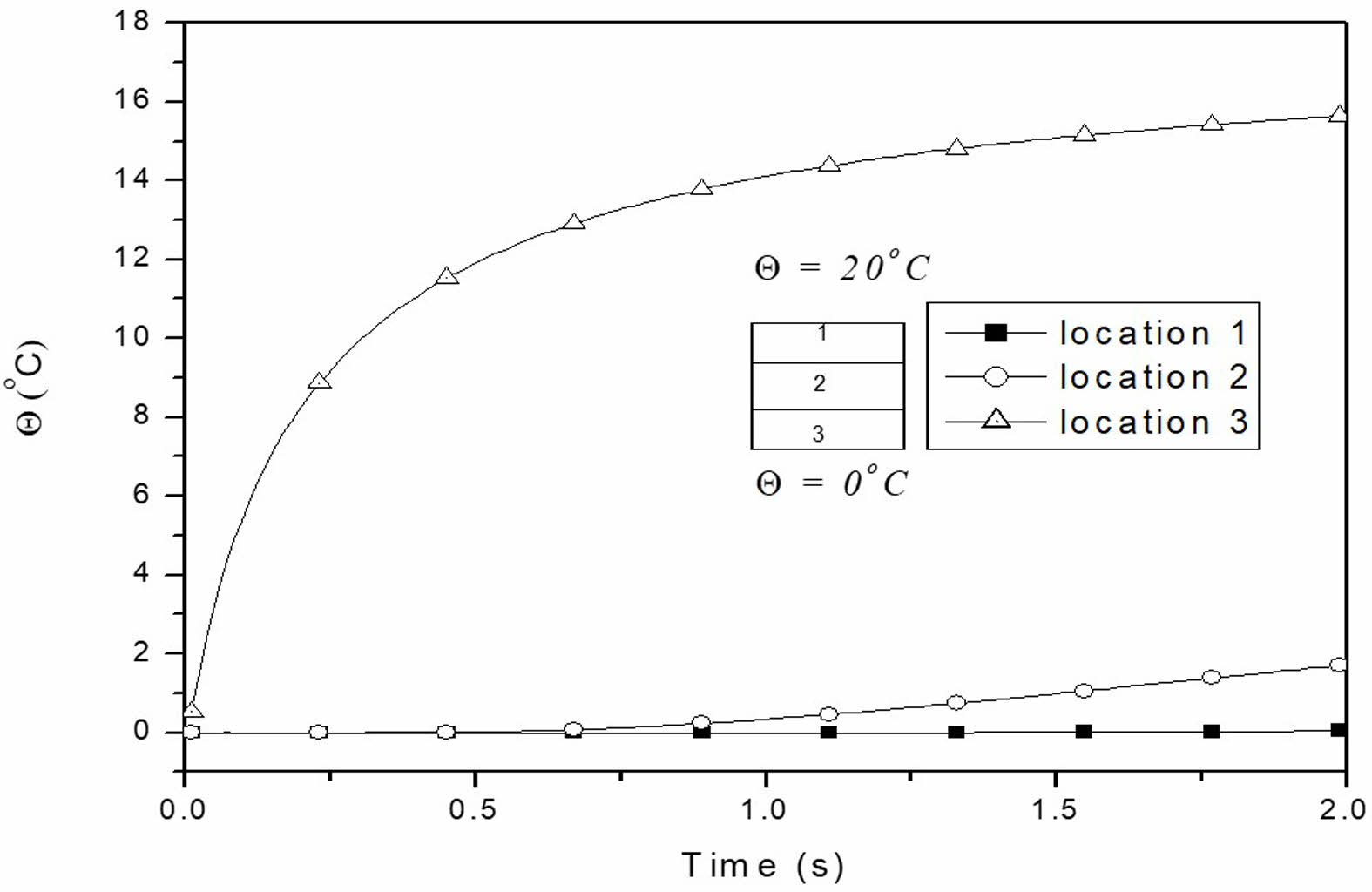
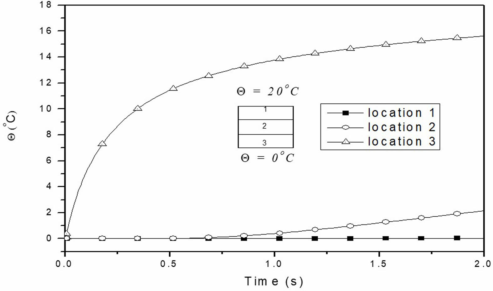
The thermal boundary conditions for the layered and multiphase MEE beam are uniform along the length and vary only across the thickness (Fig. 2). The temperature histories at different points along the thickness of the layered MEE beam with B/F/B and F/B/F stacking sequences are shown in Fig. 5 and 6.
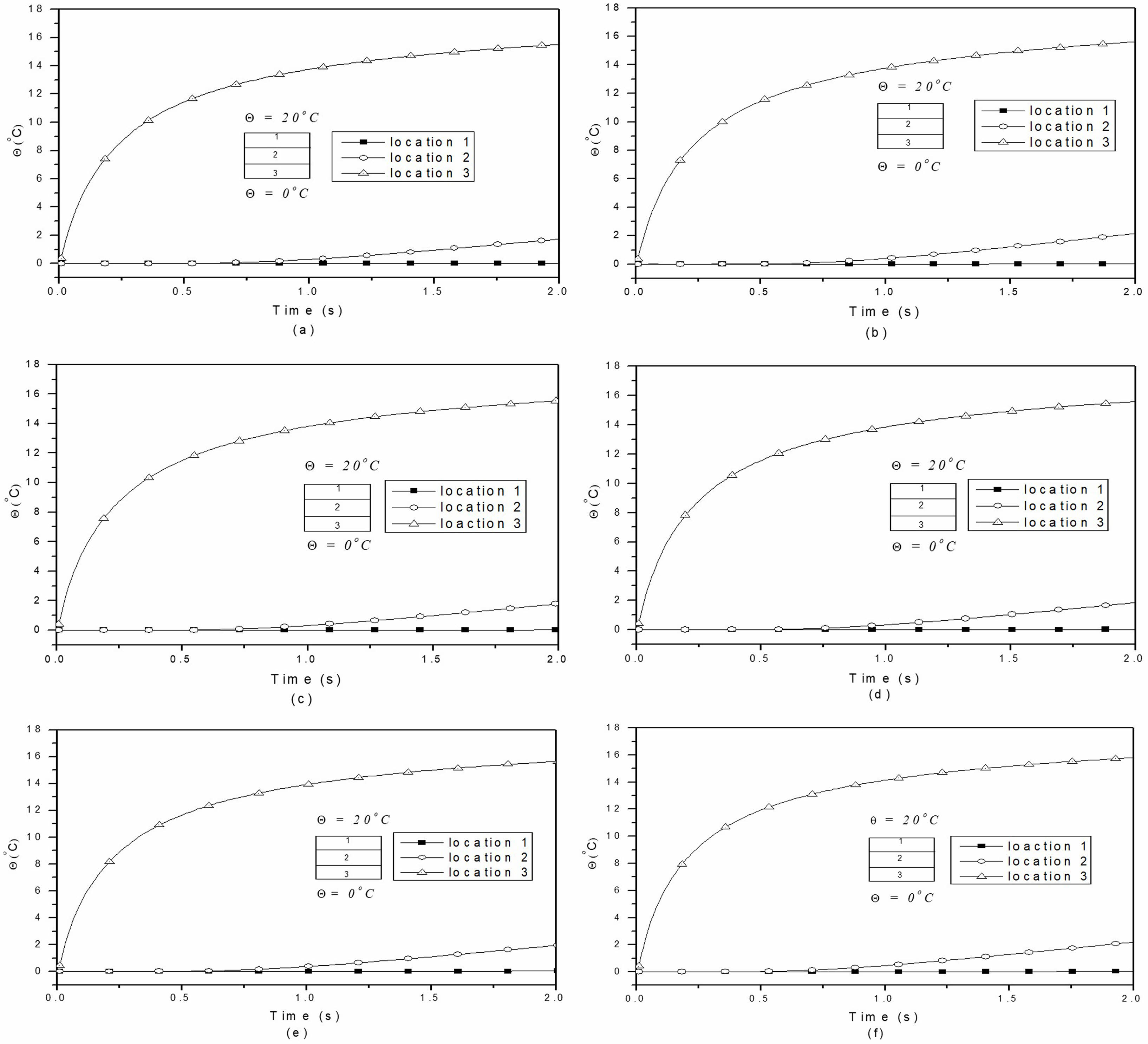
Due to an increase in thermal conduction (approximately 21%) in the piezomagnetic phase, the temperature buildup is observed to be higher for the F/B/F stacking sequence. Fig. 7(a) to 7(f) illustrate the temperature distributions across the thickness of multiphase MEE beams with varying volume fractions. As the volume fraction increases, the temperature distribution decreases, a trend attributed to the thermal conductivity of the piezoelectric material.
Mechanical Response
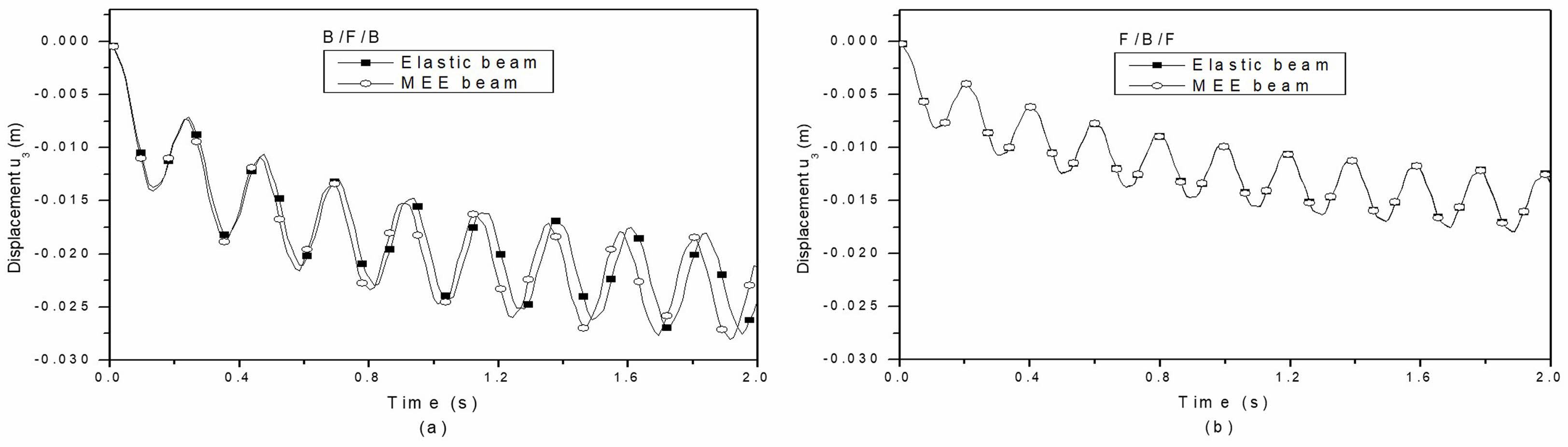
The thermally induced vibrations of a layered MEE cantilever beam subjected to transient thermal loading, focusing on the B/F/B and F/B/F stacking sequences is studied. It is assumed that each layer has an equal thickness. The mechanical response is plotted at the free end of the MEE cantilever beam. The effect of coupling on the mechanical response of layered MEE beams with B/F/B and F/B/F stacking sequences is illustrated in Fig. 8(a) and (b), respectively. Layered MEE beams with a B/F/B stacking sequence exhibit a greater sensitivity to coupling effects in terms of mechanical reaction. This is attributed to the presence of additional piezo components, which enhance the coupling effects.
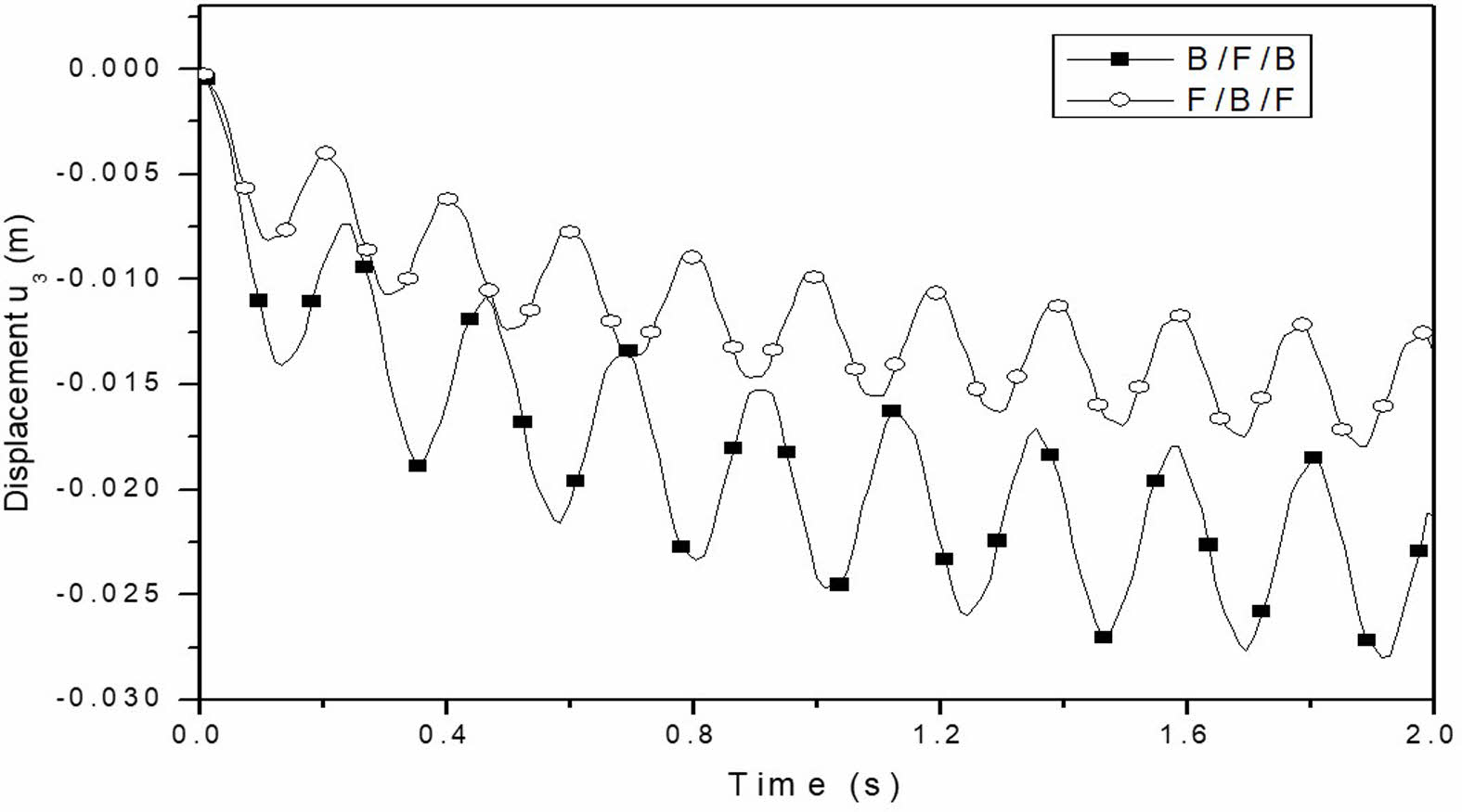
Fig. 9 demonstrates the influence of the B/F/B and F/B/F stacking sequences on the mechanical response of layered MEE cantilever beams. The mechanical response is greater in layered MEE cantilever beams with a B/F/B stacking sequence compared to those with an F/B/F stacking sequence. This difference is attributed to the larger stiffness coefficient of the piezomagnetic phase, indicating that the mechanical response is dependent on the system’s overall stiffness.
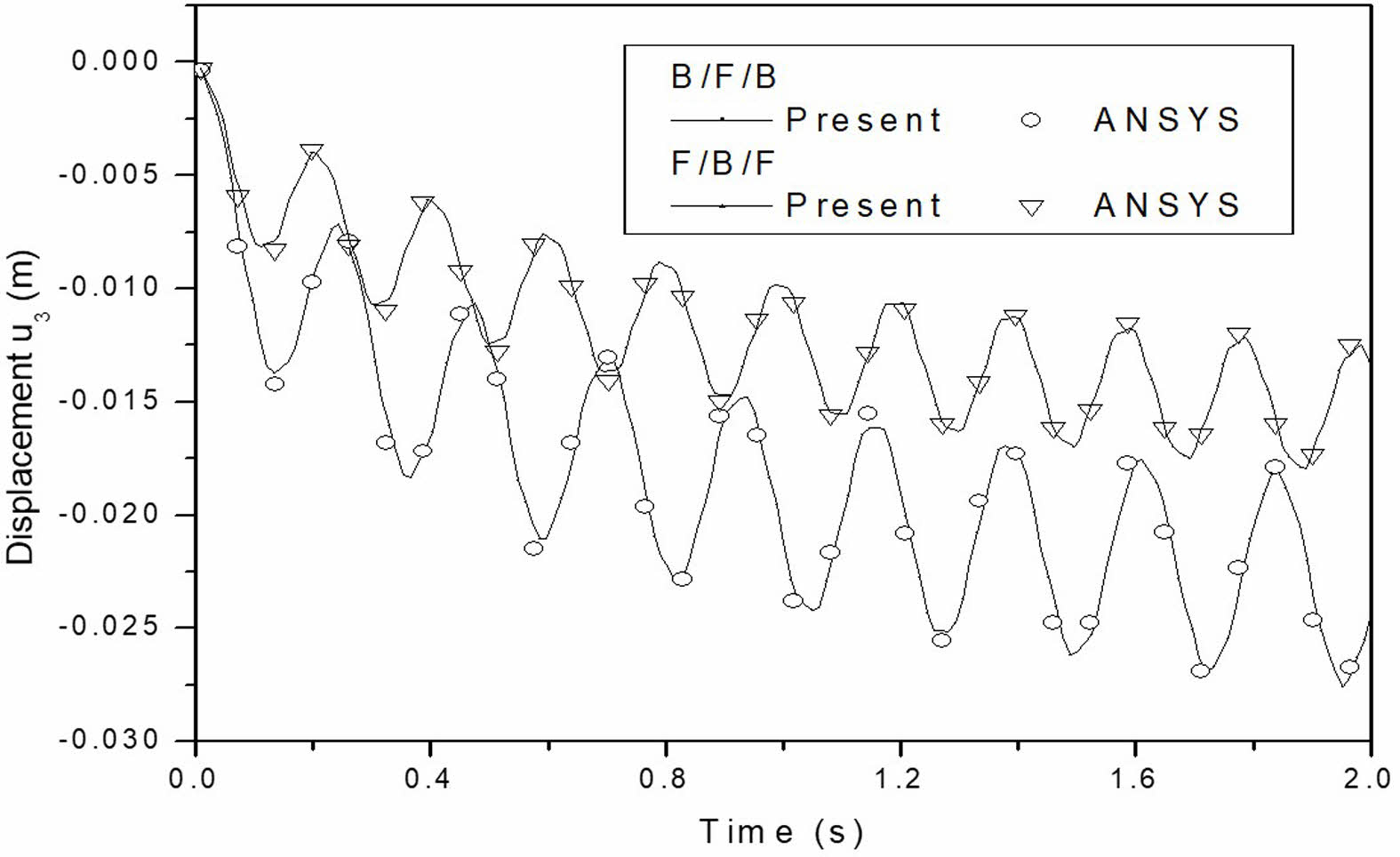
Furthermore, to verify the results, the uncoupled mechanical responses of stacked MEE beams with B/F/B and F/B/F stacking sequences are compared with those obtained from ANSYS. The comparison of the uncoupled mechanical responses is presented in Fig. 10, showing a strong agreement between the ANSYS results and the current findings.
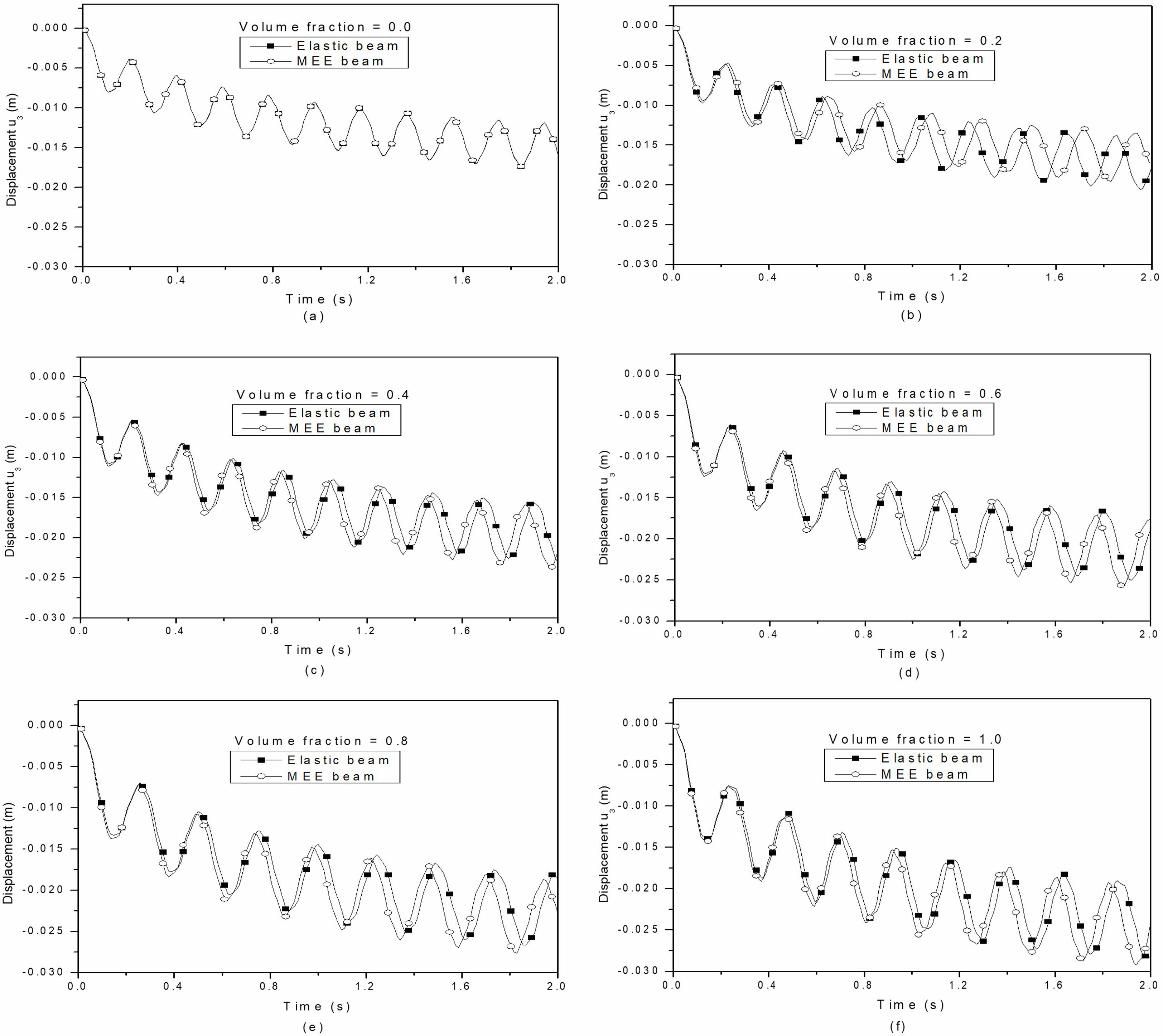
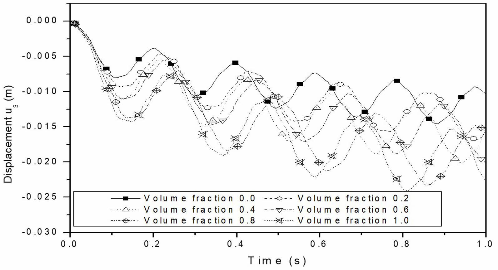
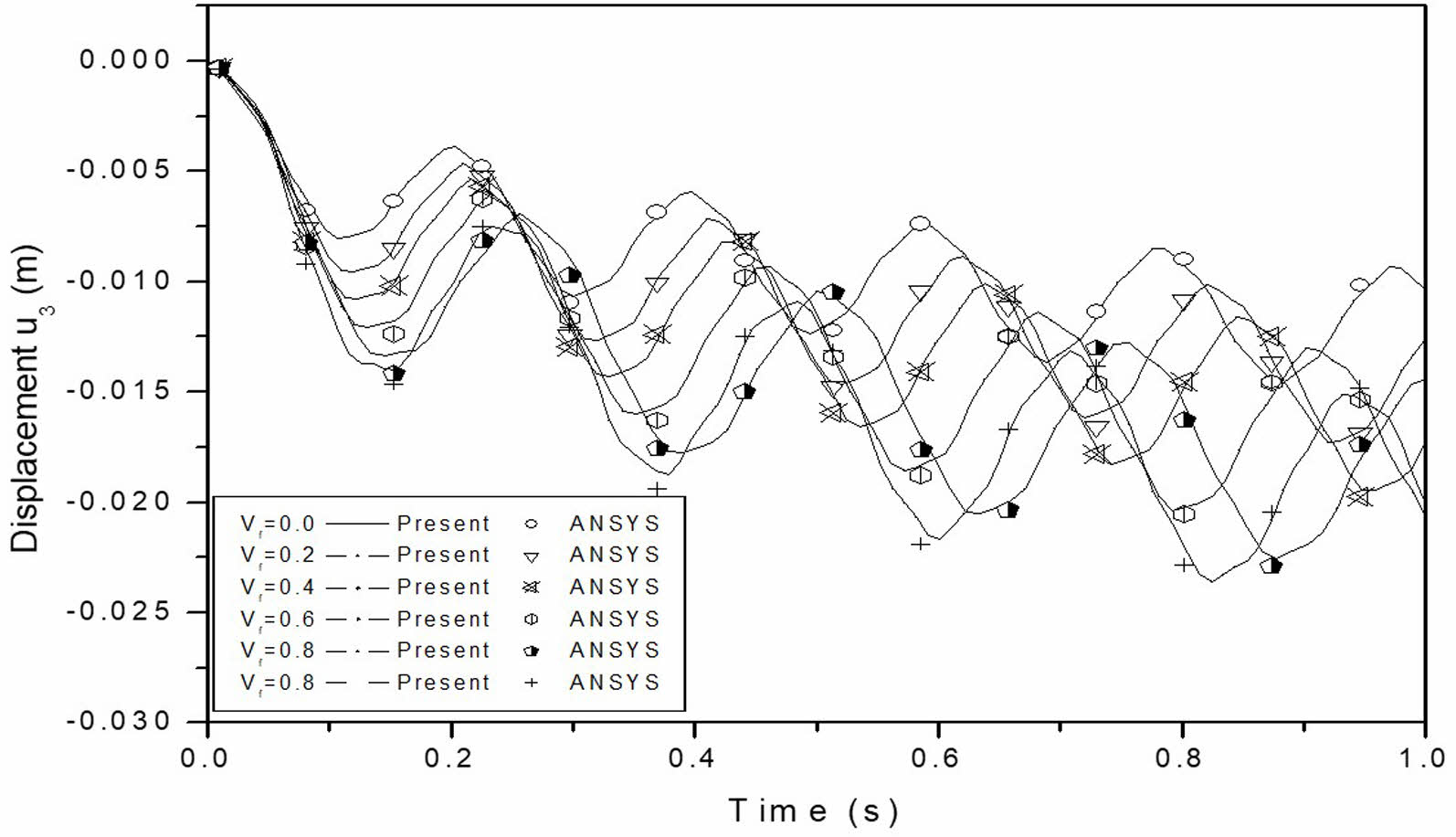
Fig. 11(a) to (f) shows the effect of coupling on the mechanical response of multiphase MEE cantilever beams with different volume fractions. It is observed that the effect of coupling is to produce the phase shift on mechanical response. The phase shift is due to the coupling of the multiphase MEE system and is quite different on volume fraction 0.2. The frequency of the coupled system is higher due to coupling for all volume fractions whereas it is lower for multiphase MEE beam with volume fraction 0.2. The effect of the BaTiO₃ volume fraction in the BaTiO₃-CoFe₂O₄ composite on the mechanical response of a multiphase MEE cantilever beam is illustrated in Fig. 12. The mechanical response of the multiphase MEE beam is influenced by the thermal load applied. The magnitude of the response is primarily determined by the system’s stiffness, which decreases as the volume fraction increases. Consequently, this reduction in stiffness leads to an increase in the magnitude of the system’s mechanical response. Fig. 13 presents the comparison of the uncoupled mechanical response of the multiphase MEE system with varying volume fractions, showing a strong correlation between the ANSYS results and the current study.
Electric Response
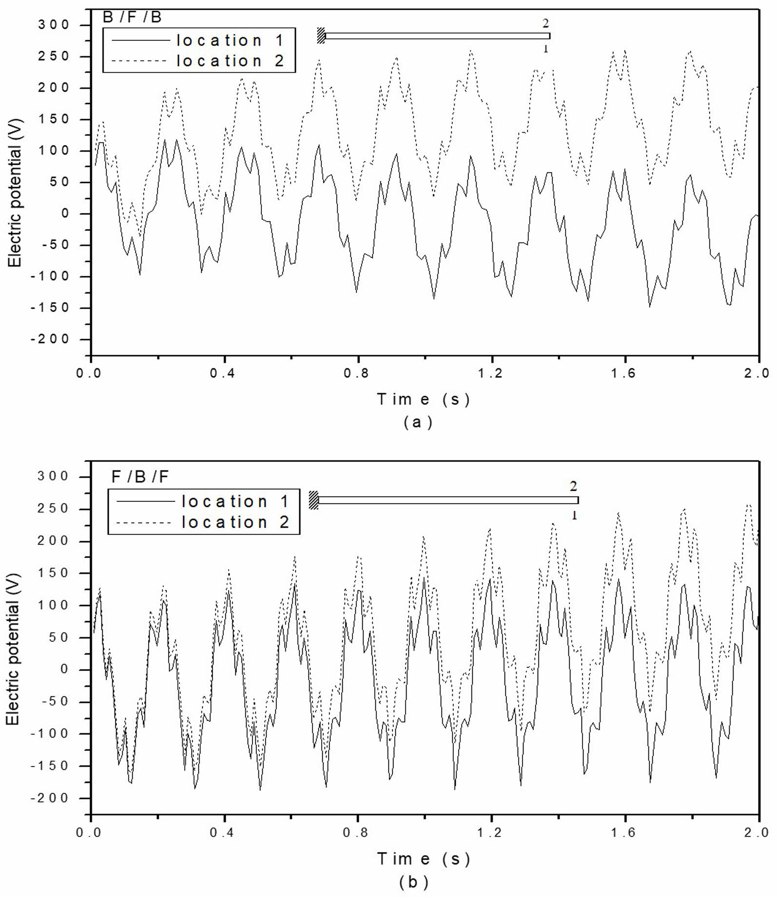
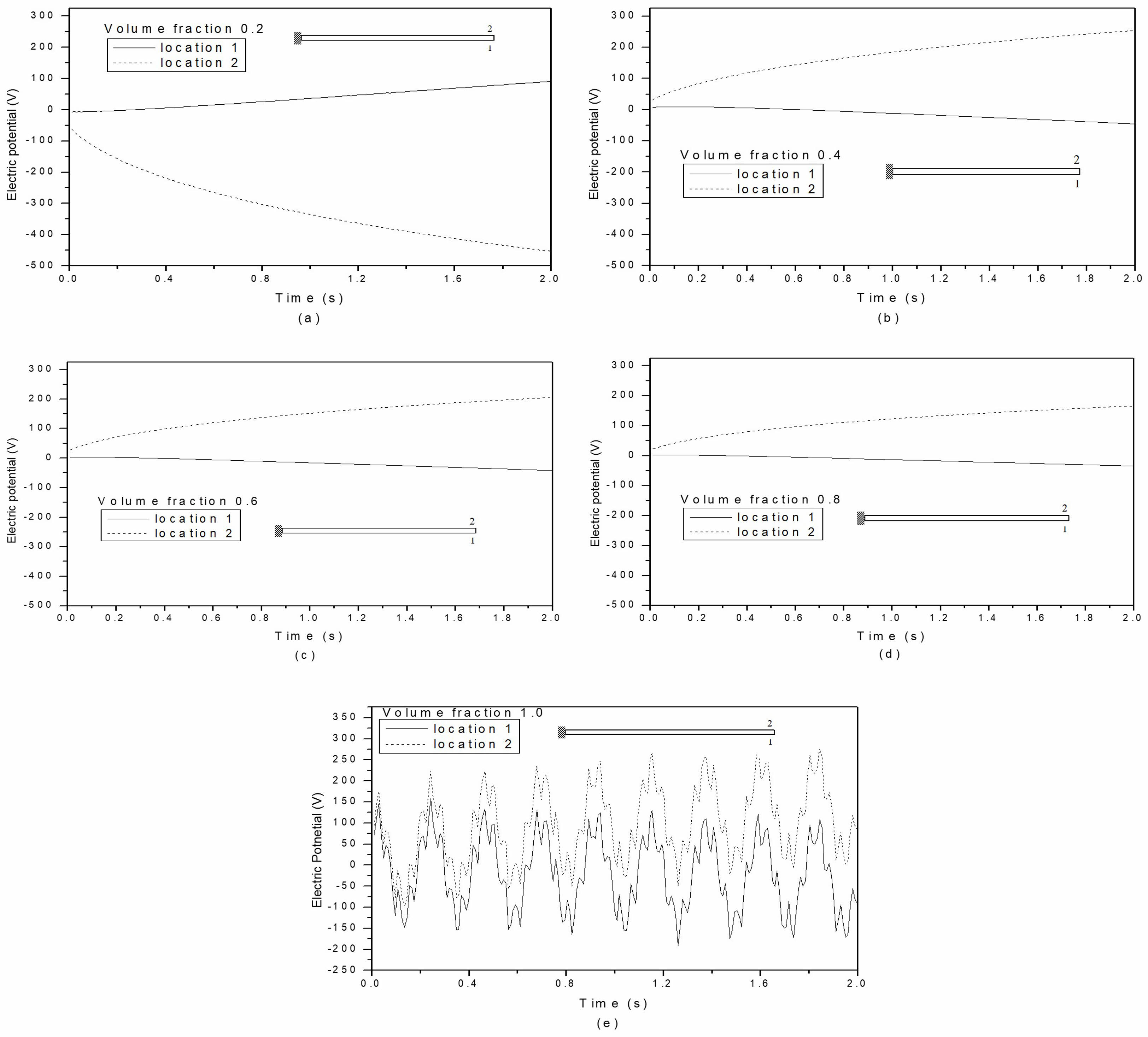
Variations in the electric response for stacked MEE beams with B/F/B and F/B/F stacking sequences are illustrated in Fig. 14(a) and (b), respectively. The electric response is plotted at the position of maximum deflection in the stacked MEE cantilever beam. It is clear that the electric response mirrors the displacement pattern. Notably, the layered MEE beam with the B/F/B stacking pattern displays a greater electric response magnitude. For both stacking sequences, the top layer experiences a larger electric response due to its higher thermal expansion. The variation in electric response for multiphase MEE beams with volume percentages of 0.2, 0.4, 0.6, 0.8, and 1.0 is illustrated in Fig. 15(a) through (e). At a volume fraction of 0.0, the piezoelectric coefficients are zero, resulting in no electric response. The multiphase MEE beams with volume fractions of 0.2, 0.4, 0.6, and 0.8 exhibit an odd characteristic in their electric response. This may be attributed to the strain constant being zero for these volume fractions. Since the strain constant e15 is still present, the electric response of the volume fraction representing pure piezoelectric material aligns with the displacement pattern.
Magnetic Response
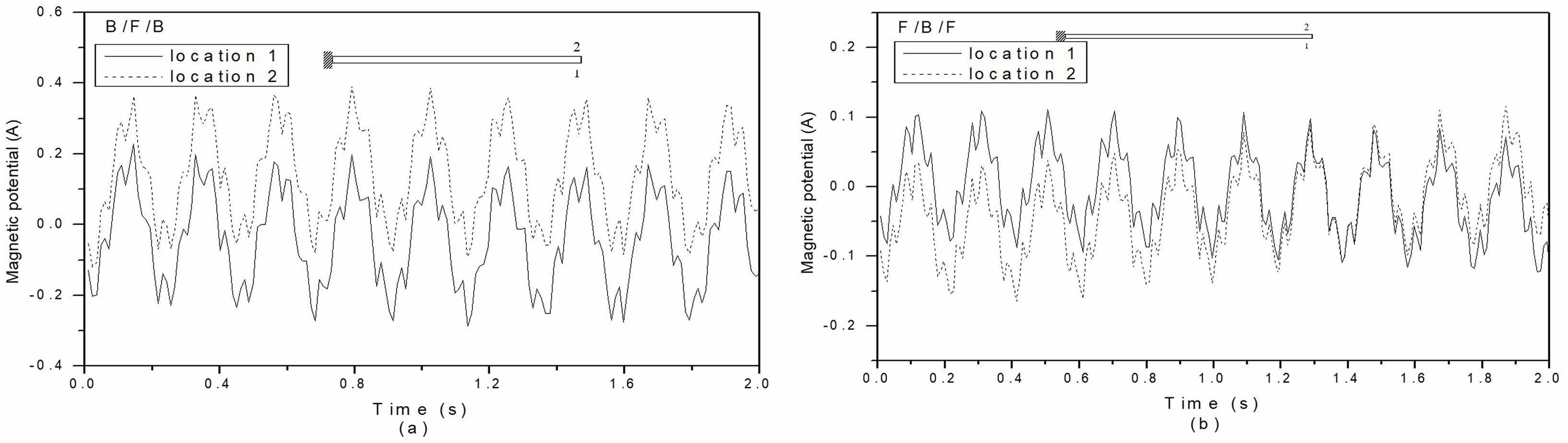
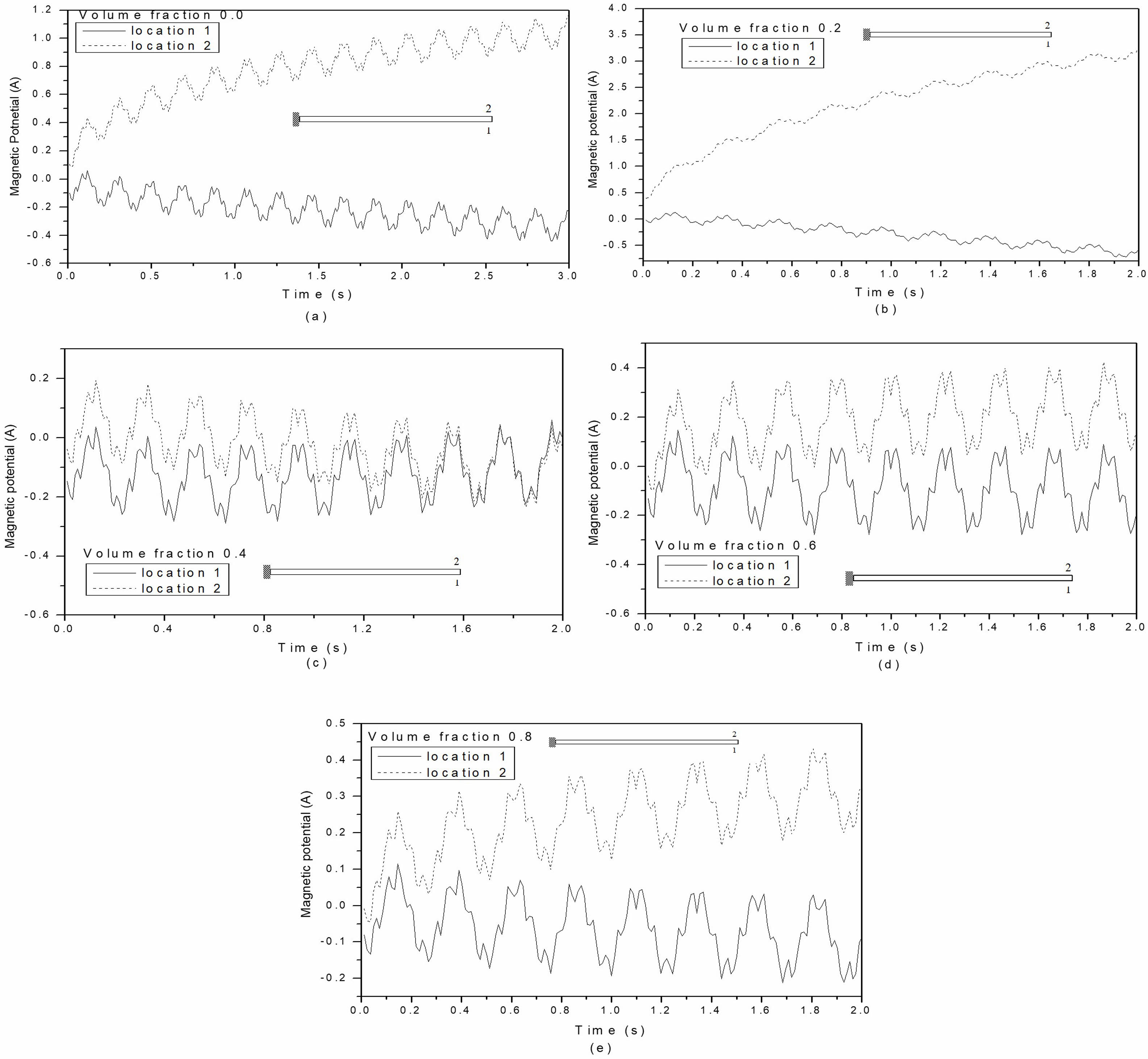
The magnetic response of stacked MEE beams with B/F/B and F/B/F stacking sequences is shown in Fig. 16(a) and (b). The magnetic response is greater in stacked MEE beams with F/B/F stacking sequences compared to those with B/F/B stacking sequences. The magnetic response of the multiphase MEE cantilever beam with volume fractions of 0.0, 0.2, 0.4, 0.6, and 0.8 is illustrated in Fig. 17(a) to (f). At a volume fraction of 1.0, the piezomagnetic coefficients are zero, resulting in no magnetic response. The multiphase MEE beam with a volume fraction of 0.2 shows a greater magnetic response compared to the other volume fractions. As expected, volume fraction 0.0 exhibits a higher magnetic potential response than those of 0.4, 0.6, and 0.8; however, volume fraction 0.2 also demonstrates a greater magnetic potential response than volume fraction 0.0.
|
Fig. 5 Temperature build-up across the thickness for layered MEE beam with B/F/B stacking sequence. |
|
Fig. 6 Temperature build-up across the thickness for layered MEE beam with F/B/F stacking sequence. |
|
Fig. 7 Temperature build-up across the thickness for multiphase MEE beam with volume fraction (a) 0.0 (b) 0.2 (c) 0.4 (d) 0.6 (e) 0.8 (f) 1.0. |
|
Fig. 8 Effect of coupling on mechanical response of layered MEE beams for (a) the B/F/B stacking sequence and (b) the F/B/F stacking sequence. |
|
Fig. 9 Mechanical response of stacked MEE beams with B/F/B and F/B/F stacking sequences as a function of stacking sequences. |
|
Fig. 10 Comparison of the thermo-elastic cantilever beam's mechanical response with the F/B/F and B/F/B stacking sequences. |
|
Fig. 11 Effect of coupling on mechanical response for multiphase MEE cantilever beam with volume fraction (a) 0.0 (b) 0.2 (c) 0.4 (d) 0.6 (e) 0.8 (f) 1.0. |
|
Fig. 12 Effect of volume fraction of BaTiO3 in BaTiO3 – CoFe2O4 composite on the mechanical response for multiphase MEE beam. |
|
Fig. 13 Comparison of the mechanical response of multiphase thermo-elastic cantilever beam. |
|
Fig. 14 Variation of electric response for layered MEE beam with B/F/B and F/B/F stacking sequence. |
|
Fig. 15 Variation of electric response for multiphase MEE beam with volume fraction (a) 0.2 (b) 0.4 (c) 0.6 (d) 0.8 (e) 1.0 for location 1 and 2. |
|
Fig. 16 Variation of magnetic response for layered MEE beam with (a) B/F/B stacking sequence and (b) F/B/F stacking sequence. |
|
Fig. 17 Variation of magnetic response for multiphase MEE beam with volume fraction (a) 0.0 (b) 0.2 (c) 0.4 (d) 0.6 (e) 0.8 for locations 1 and 2. |
Using the finite element method, a computer program has been developed to analyze the transient responses of displacement, electric potential, and magnetic potential in multilayer and multiphase MEE cantilever beams. The results are validated against the commercial finite element program ANSYS using two methods. First, the temperature and thermally induced vibrations are confirmed through transient thermo-elastic analysis, as ANSYS does not address the transient behavior of coupled piezo-thermo-elastic problems. Next, the coupling terms are verified with the steady-state behavior of the piezoelectric cantilever beam under steady-state temperature distribution. The study presents the effects of stacking sequence and volume fraction on the thermal, mechanical, electric, and magnetic responses, along with the impact of coupling on mechanical response. It is observed that piezoelectric coupling significantly influences mechanical response, while the dynamic responses of electric and magnetic fields exhibit complex relationships with stacking sequences and volume fractions. This understanding is crucial for exploring the dynamic characteristics of layered and multiphase MEE materials for use as sensors or actuators in active structures.
- 1. E. Pan and F. Han, Int. J. Eng. Sci. 43 (2005) 321-339.
-

- 2. D.J. Huang, H.J. Ding, and W.Q. Chen, Int. J. Eng. Sci. 45 (2007) 467-485.
-
- 3. J.Y. Li and M.L. Dunn, J. Intell. Mater. Syst. Struct. 9 (1998) 404-416.
-
- 4. J. Aboudi, Smart Mater. Struct. 10 (2001) 867-877.
-
- 5. F. Dinzart and H. Sabar, Int. J. Solids. Struct. 48 (2011) 2393-2401.
-
- 6. K.-S. Lee, M.-S. Chae, D.-J. Shin, S.-M. Nam, J.-H. Koh, S.-J. Jeong, K.-H. Cho, and S.W. Chang, J. Ceram. Process. Res. 13[2] (2012) 278-281.
-
- 7. B.-J. Chu, J.-H. Cho, Y.-H. Lee, B.-I. Kim, and D.-R. Chen, J. Ceram. Process. Res. 3[3] (2002) 231-234.
- 8. J.H. Kim, K.W. Chae and C.I. Cheon, J. Ceram. Process. Res. 23[5] (2022) 679-684.
-
- 9. K.-H. Choa, B.G. Choid, B.-G. Lohb, Z.S. Limc, D.H. Kima, B.-J. Koa, Y.H. Kim, S.M. Kim, and K.B. Shim, J. Ceram. Process. Res. 12[5] (2011) 610-614.
-
- 10. A. Kumaravel, N. Ganesan, and R. Sethuraman, Smart Mater. Struct. 16 (2007) 282-295.
-
- 11. Y. Tian, S. Li, B. Zhang, Y. Gong, P. Liu, X. Hu, and Q. Jing, J. Ceram. Process. Res. 23[4] (2022) 430-435.
-
- 12. L. Cui, R. Niu, D. Wang, and W. Wang, J. Ceram. Process. Res. 24[2] (2023) 348-352.
-
- 13. R.F. Niu, D.P. Wang, Z.H. Huang, and W.T. Wang, J. Ceram. Process. Res. 25[2] (2024) 300-305.
-
- 14. Y. Ootao and Y. Tanigawa, Compos. Struct. 63[2] (2004) 139-146.
-
- 15. A. Kumaravel, N. Ganesan, and R. Sethuraman, Smart Mater. Struct. 16 (2007) 282-295.
-
- 16. A. Ioachim, M.I. Toacsan, and M.G. Banciu, J. Eur. Ceram. Soc. 27[2-3] (2007) 1117-1122.
-
- 17. Y. Hiruma, H. Nagata, and T. Takenaka, J. Ceram. Soc. Jpn. 112 (2004) S1125-S1128.
-
- 18. P.F. Hou, H.J. Ding, and A.Y.T. Leung, J. Sound Vib. 291[1-2] (2006) 19-47.
-
- 19. M. Sunar, Ahmed Z Al-Garni, M.H. Ali, and R. Kahraman, AIAA J. 40[9] (2002) 1846-1851.
-
- 20. Y.T. Keum, J.H. Kim, and B.Y. Ghooa, J. Ceram. Process. Res. 1[1] (2000) 74-79.
- 21. A. Jiang and H. Ding, Struct. Eng. Mech. 18[2] (2004) 195-209.
-
- 22. Y. Ootao and Y. Tanigawa, Compos. Struct. 68[4] (2005) 471-480.
-
- 23. D.J. Huang, H.J. Ding, and W.Q. Chen, Int. J. Eng. Sci. 45[2-8] (2007) 467-485.
-
- 24. E. Pan and F. Han, Int. J. Eng. Sci. 43[3-4] (2005) 321-339.
-
- 25. J. Wang, L. Chen, and S. Fang, Int. J. Solids Struct. 40[7] (2003) 1669-1680.
-
- 26. K. Gurram and N. Pannirselvam, J. Ceram. Process. Res. 24[3] (2023) 560-568.
-
- 27. W. Ye, J. Liu, Q. Zang, and G. Lin, Mechanics of Materials 148 (2020) 103495.
-
- 28. B. Biju, N. Ganesan, K. Shankar, and T.H. Hyde, Proc. Inst. Mech. Eng., Part L: J. Mater.: Des. Appl. 224[3] (2010) 123-132.
-
- 29. L. Zhou, M. Li, G. Meng, and H. Zhao, J. Intell. Mater. Syst. Struct. 29[14] (2018) 3006-3022.
-
- 30. R. Dhanasekaran, A. Kumaravel, S. Arunprasath, M. Dinesh Babu, and S. Elayaraja, J. Ceram. Process. Res. 25[1] (2024) 119-130.
-
- 31. H.L. Dai and X. Wang, Int. J. Solids Struct. 43 (2006) 5628-5646.
-
- 32. H.M. Wang and H.J. Ding, Eur. J. Mech. A. Solids 25 (2006) 965-980.
-
- 33. V. Birman, Int. J. Mech. Sci. 39[10] (1997) 1139-1149.
-
- 34. H. Zhou, C. Xu, C. Lu, X. Jiang, Z. Zhang, J. Wang, X. Xiao, M. Xin, and L. Wang, Sens. Actuators A: Phys. 329 (2021) 112789.
-
- 35. M. Bodaghi and M. Shakeri, Compos. Struct. 94 (2012) 1721-1735.
-
 This Article
-
2025; 26(2): 267-279
Published on Apr 30, 2025
- 10.36410/jcpr.2025.26.2.267
- Received on Feb 5, 2025
- Revised on Feb 13, 2025
- Accepted on Feb 28, 2025
Services
Shared
Correspondence to
- Dhanasekaran Rajagopal
-
Department of Mechanical Engineering, Adhiyamaan College of Engineering, Hosur, Tamil Nadu – 635109, India
Tel : +91 9043793491 Fax: 04288 - 274745 - E-mail: dr.r.dhanasekaran@gmail.com
Clean-Energy Research Institute(CRI), Hanyang University, 222, Wangsimni-ro, Seongdong-gu, Seoul, 04763, Korea
E-mail: jcpr@hanyang.ac.kr