- Effect of cracks and optimizations of high strength concrete beams with hybrid fibre reinforced polymer (HYFRP) laminates
P. Somiyadevia,* and V. Ramasamyb
aAssistant Professor, Department of Civil Engineering, Adhiparasakthi Engineering College, Melmaruvathur, Tamil Nadu, India-603319
bProfessor, Department of Civil Engineering, Adhiparasakthi Engineering College, Melmaruvathur, Tamil Nadu, India-603319This article is an open access article distributed under the terms of the Creative Commons Attribution Non-Commercial License (http://creativecommons.org/licenses/by-nc/4.0) which permits unrestricted non-commercial use, distribution, and reproduction in any medium, provided the original work is properly cited.
This Research article illustrates Effects of cracks and optimization on the strengthening of HSC beam with the addition of hybrid FRP laminates under the flexural type of loading. This current research work intends to study how alternative sequences of carbon FRP (CFRP) and glass FRP (GFRP) laminates with the combinations of hybrid FRPs effect the enhancement of the reinforced cement concrete beams. For this research investigation, 17 rectangular beams were cast and prepared using Glass FRP and Carbon FRP. Out of the casted beam, one beam aided as a control concrete beam and the remaining 16 beam were supported by the use of hybrid Fibre Reinforced Polymer laminates in the form of glass and carbon. Concrete with reinforcements after laminating beams with two, three, and even four layers of HyFRP and a static type of load was given to the beam until they failed. The initial and progressive fractures of HSC beam, as well as beam failure both without and with hybrid FRP laminates were investigated and analysed. Comparisons and presentations of analytical and experimental data were done with the intention of deriving new findings. The conclusions of the tests lead one to the assumption that the consequences of hybrid FRPs on the cracks and ductility of High Strength Concrete beams are strengthened differently depending on the order of the FRP layers.
Keywords: Carbon fibre laminates, Glass fibre laminates, Tensile strength, Modulus of elasticity, Modelling, Elongation.
According to the findings of recent studies, concrete will continue to be the material of choice for the construction of many human-made structures in the decades to come. The malleability of concrete results from the fact that its composition may be modified in addition to the standard cement, aggregate, and water ingredients in order to accommodate the requirements of any specific environment The outcome of this it is now feasible to manufacture concrete that satisfies all of the performance standards that are relevant, which is fantastic news In the past ten years, advancements in material research and the widespread use of high-strength concrete have made it possible to produce concrete with improved mechanical characteristics and structural behaviour Concrete with enhanced structural behaviour allowed for this to be built. Despite the growing popularity of high-strength concrete, no new standards for its usage have been established. Now a day’s ultimate task in the construction industry is the maintenance of the existing structure because of the irrelevant type of construction over the years. To overcome this kind of problem in structures Fibre reinforced polymers (FRP) have been introduced recently for strengthening construction. Most of the traditional methods of construction practices have been developed and implemented and structural rehabilitation because of their greater strength value to their ratio of weight, resistance against corrosion and ductility. Most of the construction works are carried out by using FRP laminates made with glass, carbon and aramid fibres.
Glass fibre-reinforced polymers are economical when associated with carbon fibre and aramid fibres. In this present research work, GRFP and CFRP were taken because of the cost and strength factor for assessing the performance of the hybrid FRP laminated high-strength concrete beams. The main attention is on the strength and deflection properties of Hybrid FRP (HYFRP) strengthened high-strength concrete (HSC) beams.
Most of the research persons supported experimental studies on reinforced cement concrete beams supported with glass, carbon, and aramid FRP composites (GFRP, CFRP & AFRP) to evaluate their effectiveness and also retrofitting of concrete beams using FRP was done. After 1980 the corrosion resistance steel plates are replaced for repair and rehabilitation works instead of these material fibre fibre-reinforced polymers are introduced in the form of sheets, laminates and wraps. Fibre Reinforced Polymer sheets have many advantages for the repair and rehabilitation of the existing building.
Analysis of components and systems under a wide range of loading circumstances is increasingly relying on experimental methods. Whereas experimental methods are effective in capturing responses and behaviours in real-world settings, they are time-consuming and can be costly. That’s why Finite Element Aanlysis is becoming more and more important for structural analysis, it can simulate structural components with realistic stresses, boundaries, and material behaviour. ANSYS 2022 finite element software is used for the numerical simulations. It is ideal to be able to forecast the consequences, such as variations in strain and stress, when a reinforced concrete beam, column, or beam column junction is subjected to nonlinear changes.
Examined behaviour and ductility performance of Reinforced Concrete beam utilising the Carbon Fibre Reinforced Polymer [1-4]. From the results of experimental work FRP laminate increased beam energy absorption, load bearing capability, and fracture delay. CFRP sheeting enhanced beam shear strength and that FRP should be oriented 45° to the beam axis [5]. Use of beams that had high ratio of longitudinal tensile reinforcement and an adequate amount of longitudinal tensile reinforcement. The findings demonstrated that there was a negative correlation between depth of failure along with ductility of beam and neutral axis [6]. A two-point loading system tested the beam with externally epoxy-bonded CFRP sheets to defect. CFRP fabric strengthened RC beams increased load bearing capability and rigidity [7-8]. Performance characteristics of GRFP-reinforced HSC beams were one of the things that depended on them. The proposed regression equations were able to accurately predict different parameters of GFRP laminated HSC beams [9-10]. They have utilised the findings of these experiments to validate the applicability of a previously reported (and also validated) theoretical model for NSC to case of damaged HSC beams, similarly to investigate potential implications of external loading configurations on a variety of experimental and theoretical findings [11-14]. The confining stress was changed between 0 and 3 MPa, while compression steel ratio was changed between 0 and 2.5%. Both of these variables were changed simultaneously. These two values are both expressed in MPa. This was established that flexural ductility of a structure may greatly increase by addition of reinforcement [15-18]. The experimental variables that were thought to be important for this study were tensile reinforcement ratios of 1.7%, 1.1%, 0.8% and 0.5%. Author came to a conclusion that the amount of deformation experienced by GFRP reinforced concrete beams was reduced with increase in reinforcement ratio [19]. The test findings indicated that reinforcement ratio and concrete strength affect CFRP, GFRP, RC beams and reduce deflection as well as fracture width [20-21, 45]. In most cases, the proportion of primary reinforcement fell somewhere in the range of 0.8% to 5.5%. Each beams full length of 2600 millimetres was supported by a single basic support, and the beam was loaded at both its midway [22]. Beams that had been fortified with GFRP laminates performed significantly better when compared to beams that had not been plated. The use of GFRP laminates demonstrates an increase in both deformability and strength [23-30]. Rise in compressive strength of concrete resulted in enhancements in flexural rigidity as well as enhancements in the cracking moment and displacement ductility simultaneously [31]. Four-point bending checked all beams. Bonding CFRP plates increased flexural strength, and beams strengthened with steel and CFRP had appropriate deformation capacity [32]. The flexure strength of four of the beams was intentionally designed to be low, and they were strengthened with 70% less main bottom steel and shear stirrups than originally specified. They poured M30 grade concrete for all beams. An effective wrapping technique was found to boost concrete’s flexural and shear strengths [33-35]. All strengthened experimental beams of the tensile steels strains were always higher than the CFRP strains when compared with the FEA program [36]. The hybrid beam exhibit a maximum decrease in deflection at ultimate load of 68% when compared with the reference beam. Flexural cracks were observed in all the beam specimens. The observed cracks were mostly inconstant moment region. All the beam specimens failed in flexure mode only [37, 39-40]. All the above beams were tested until failure. The experimental results show that a fibre volume proportion of 40:60 (polyolefin-steel) has significantly improved the overall performance of the tested beams [38]. The ultimate strength of RC beams strengthened with CFRP sheets is almost the same regardless of load history at the time of strengthening [41]. Mehmet Mustafa Onal examined CFRP and GFRP strengthening reinforced concrete beams. Cast and tested were 9 Nos of 150×250×2200 mm CFRP, GFRP, and control beams. Concrete was M20. CFRP and GFRP enhanced shear beams. Four-point bending tested the beams. CFRP and GFRP reinforced beams showed increased strength and energy absorption. Rami Hawileh investigated RC beams enhanced using outwardly joined hyFRP systems. Under four-point bending, five beams including one control beam were assessed. A 240 mm-deep, 1840 mm-long, 120mm-wide beams two 10 mm steel bars provided flexural reinforcement. Top hangar bars were two 8 mm steel bars. To prevent shear failure, 80mm c/c two-legged stirrups were 8mm diameter. Depending on the Carbon/Glass sheet mix, the reinforced beams had 30% to 98% more load capacity than the control RC beam.
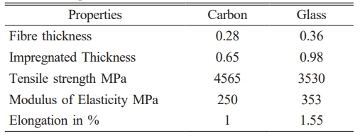
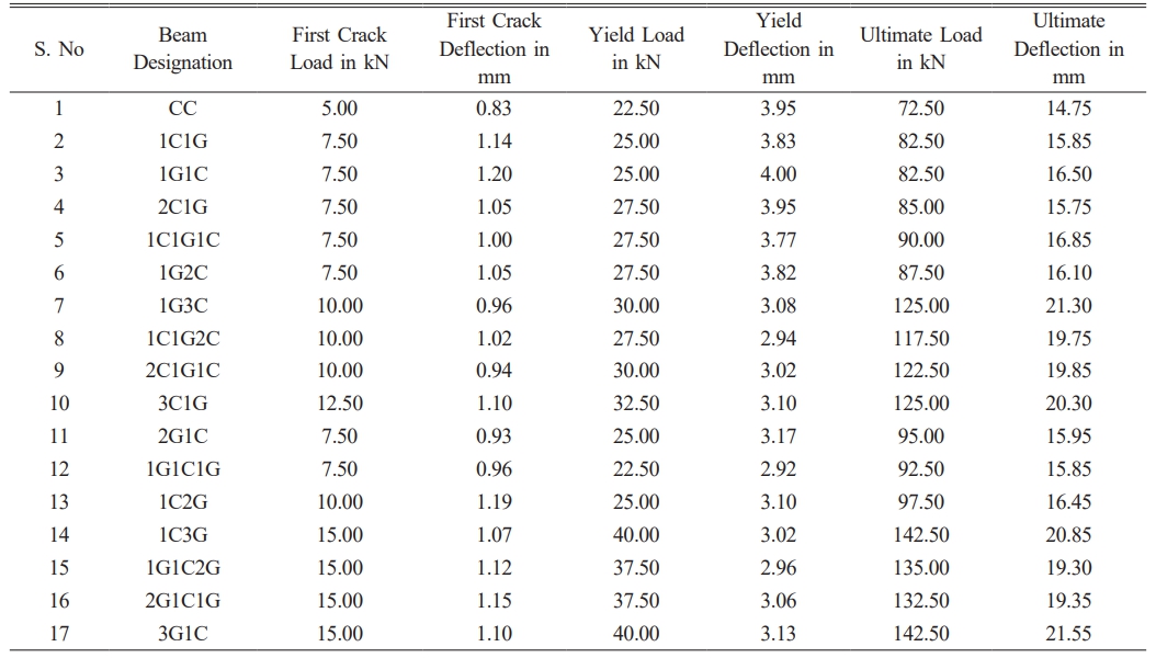
For the experimental research work seventeen beam specimens were cast under the dimensions of 150 millimetres wide 250 millimetres deep and 3000 millimetre length. All the beam specimens had been strengthened by using Reinforcement with 12 mm diameter acting as tension reinforcement and 10 mm diameter bars were provided at the top and acted as the compression reinforcement. For shear resistance, two numbers of 8 mm diameter bars spaced 125mm from centre to centre are also used. Out of seventeen beams, sixteen beams were laminated by the use of hybrid Fibre Reinforced Polymer laminates in the organisation of glass FRP and carbon FRP. Beams are supported on one side and testing is carried out under four-point loading. The experimental tests are made by the usage of carbon FRP and glass FRP in the form of woven. Table 1 represents an indication of the most important properties of the produced FRP strengthening materials. Table 2 shows Experimental Results of tested beams.
Effect of HyFRP Laminates on Failure Modes and Crack Patterns
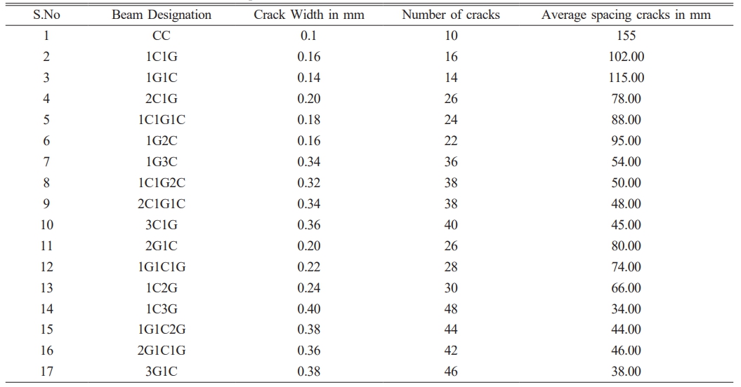
During testing, trial beams showed substantial vertical deflection and flexural cracking that was almost failure-level. It was noted that the cracking was well spread and tightly spaced. There was not a single instance of unexpected catastrophic collapse among the beams. As soon as concrete reaches its tensile strength, flexural cracks start to show up in area known as constant moment region. The cracks increase in height as loading goes on, but they maintain a limited width throughout whole loading history and are significantly less extensive than cracking that happens at reinforced concrete beams. This exemplifies the constraining impact that the lamination has on the openings of cracks. Table 3 shows Test results of Cracks on the Tested Specimens. Table 4
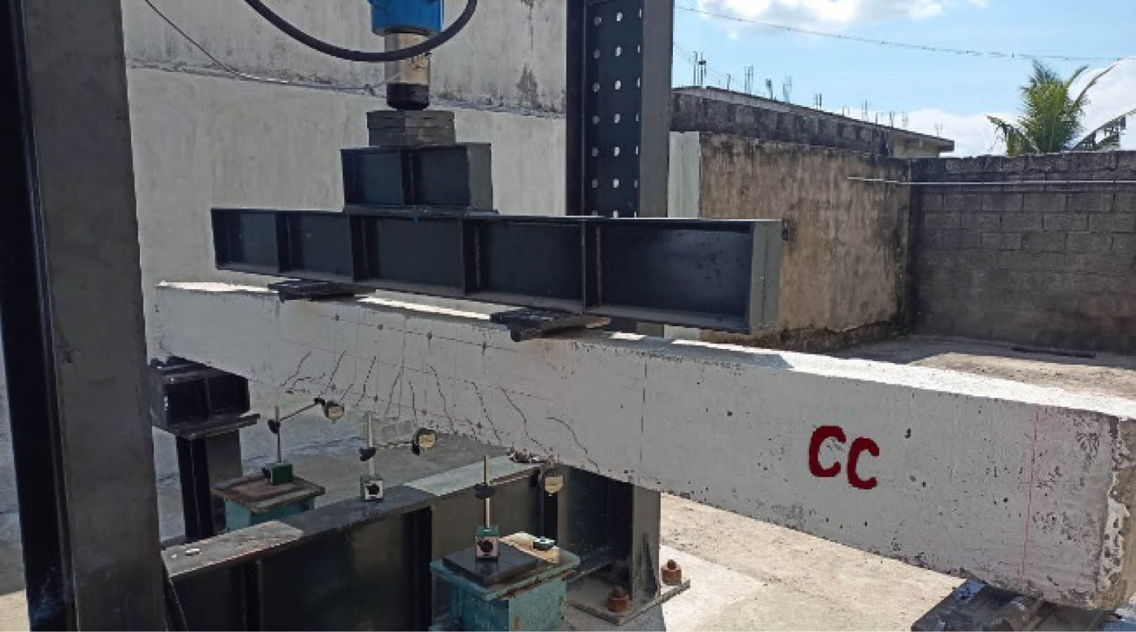
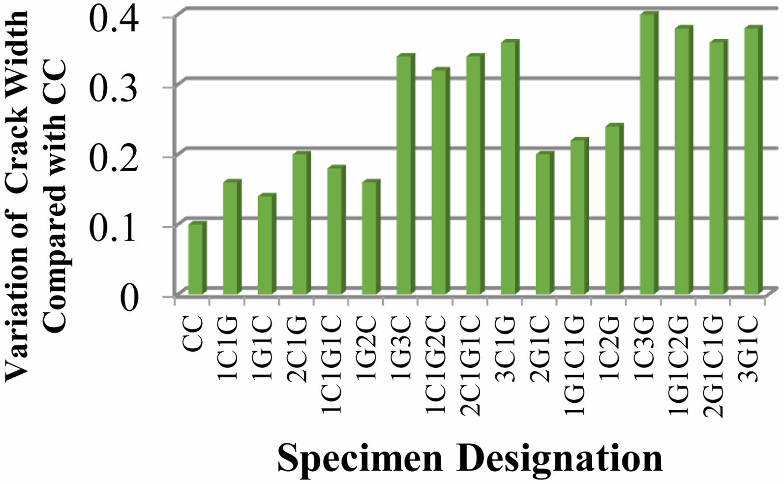
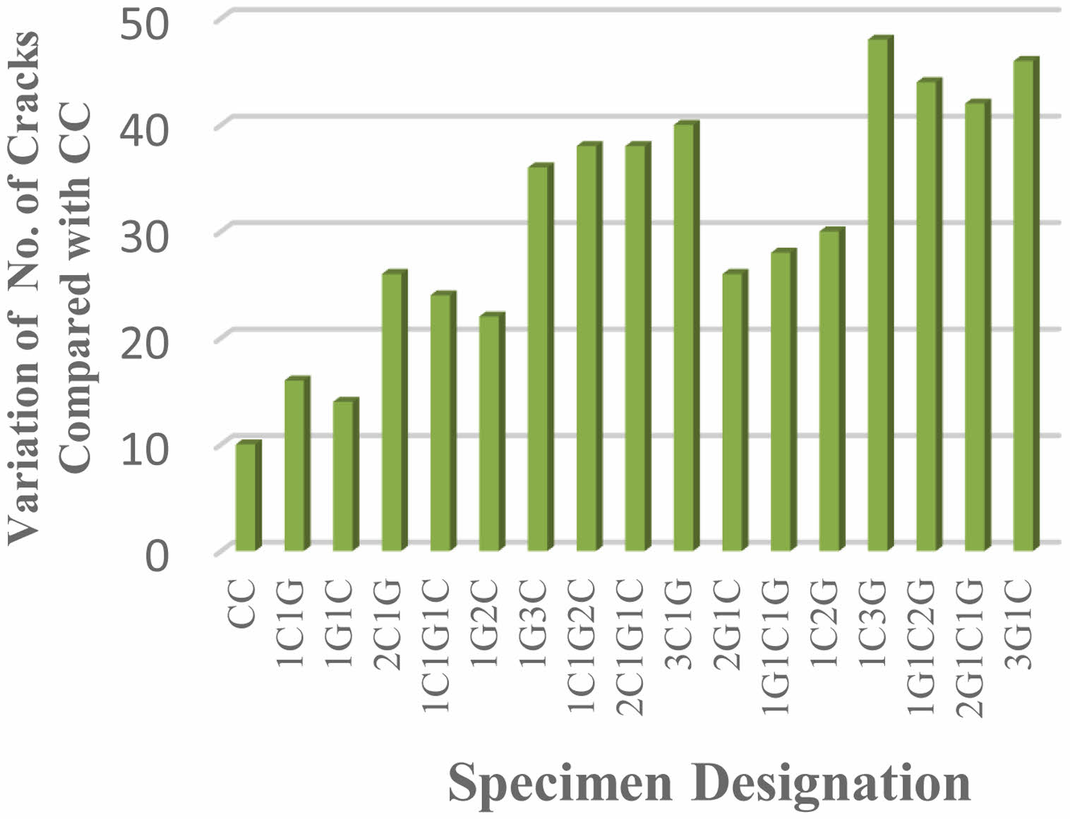
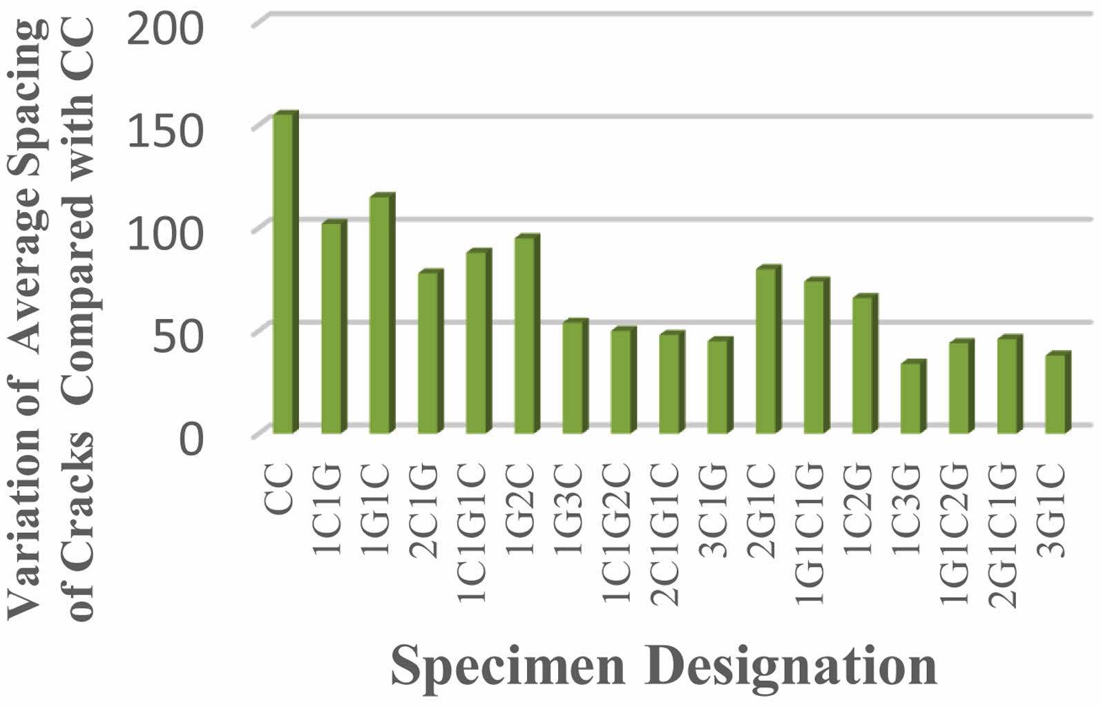
Fig. 1 shows Crack Pattern and Failure Mode of CC Specimen. Fig. 2, Fig. 3 and Fig. 4 shows Crack Width, Number of Cracks and average spacing of cracks at ultimate stage. In the level of ultimate load, number of fractures was found to be decreased by 1C1G and 1G1C hyFRP laminates for HSC beams by a factor of 60% and 40%, respectively. For HSC beams using 2C1G, 1C1G1C, and 1G2C HyFRP laminates, the number of cracks was found to be decreased to 160%, 140%, and 120%, respectively, at the ultimate load level. This reduction was determined to be possible.
For HSC beams using 2G1C, 1G1C1G, and 1C2G HyFRP laminates, the number of cracks was found to be decreased by 160%, 180%, and 200% at the ultimate load level, respectively. For reinforced concrete beams containing 1G3C, 1C1G2C, 2C1G1C, and 3C1G hybrid FRP laminates, the number of cracks was found to be decreased by 260%, 280%, 280%, and 300% at ultimate load level, respectively. This was determined after testing. The number of fractures was found to be decreased by 380 per cent, 340 per cent, 320 per cent, and 360 per cent at the ultimate load level for HSC beams that were constructed with 1C3G, 1G1C2G, 2G1C1G, and 3G1C hybrid fibre-reinforced polymer laminates. The average crack spacing was decreased by 9.7% and 13.5% in ultimate load level for HSC beams that were laminated with either 1C1G or 1G1C hybrid FRP.
|
Fig. 1 Crack Pattern and Failure Mode of CC Specimen. |
|
Fig. 2 Crack Width at Ultimate Stage. |
|
Fig. 3 Number of Cracks at Ultimate Stage. |
|
Fig. 4 Average Spacing of Cracks at Ultimate Stage. |
In order to get closed-form answers while doing structural analysis, linear elastic models are frequently used as the basis. For situations with high levels of material and geometric non-linearities, these solutions is not work. It is ideal to be able to forecast the consequences, such as variations in strain and stress, when a reinforced concrete beam, column, or beam column junction is subjected to nonlinear changes. Because of the load, cracks emerge in the concrete’s tension zone, disrupting the stress route and altering the load transfer at the fractured region.
The beams behaviour in the experiments was modelled using the finite element version of ANSYS, which was employed in this investigation (ANSYS 2022). Before ANSYS finite element model can be constructed and utilised successfully, there are a number of stages that need to be completed. Either graphical user interface or command line interface may be used to construct models. Both options are available (GUI). The graphical user interface was utilised throughout the design process of this device. In this section, I have discussed the myriad of actions and contributions that went into development of FEM.
Steel Reinforcement
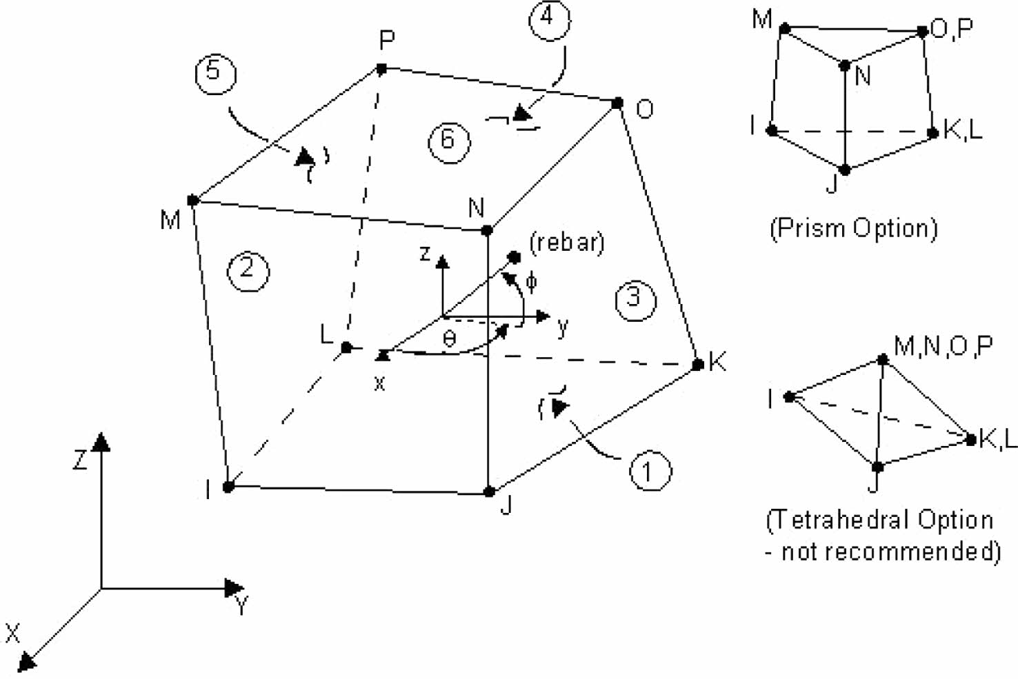
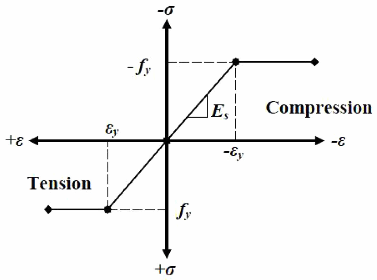
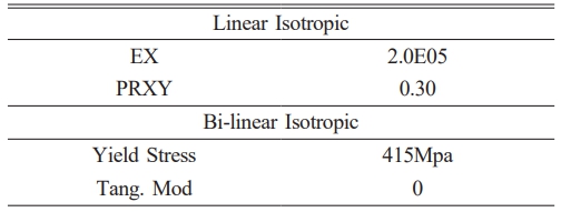
As can be seen in Table 5, Link180 modelling element was useful for simulate the steel reinforcement. This three-dimensional spar substance consists two nodes and three degree of independence in X, Y, Z axes in each node, making it a uniaxial tension/compression element. The ability for plastic deformation, creep, rotation, considerable deflection, and high strain. Fig. 5 Shows Solid 65 Element for beams and Fig. 6 shows link 180 element for FRP laminate
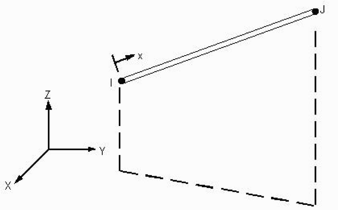
The stress-strain curve used in this FEM was based on genuine stress - strain graph that obtained during tensile testing. Fig. 7 demonstrates stress-strain comparison was used in this experiment. The following substance qualities are necessary for steel reinforcement:
· Modulus of Elasticity Mpa
· Yield stress (fy) Mpa
· Poisson’s ratio µ
Real Constants
The beam elements cross-sectional properties, represented by the real constants in Table 5, vary depending on the element type. Real constants for 2-dimensional beam element BEAM3 are “Initial Strain (ISTRN), Added mass per unit length (ADDMAS), moment of inertia (IZZ), Shear Deflection Constant (SHEARZ), HEIGHT and AREA”. Not all element types need to have a real constant, and distinct substance of same type might vary value for their real constants.
Material Properties
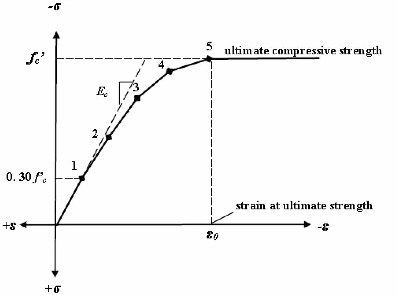
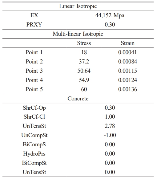
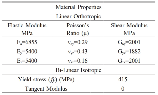
The attributes of Solid 65 components are demonstrated in Table 6, with these values, you may define material model number 1. To characterise failure of multi-linear isotropic material, von Mises’s failure criteria is used in conjunction with the model developed by Williams and Warnke (1974). Ec is the concrete elasticity modulus, Poisson’s ratio is denoted by µ.
Concrete
It is a semi-brittle material, responds differently to compression than it does to tension. The ANSYS programme calls for uniaxial stress-strain relationship for compressed concrete. Concrete uniaxial compressive stress-strain curve was generated with the use of numerical equations (Krishnan 1964 and Desayi), Eqs, (1), (2), Eq. (3) (Gere & Timoshenko, 1997).
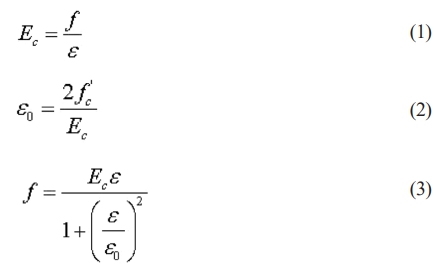
Where,
f = stress at any strain ε
ε = strain at stress f
εo= strain at the ultimate compressive strength f c’
Fig. 8 demonstrate compressive uniaxial stress-strain relationship. All beam model, streamlined stress-strain curve was built up using a total of six points and straight lines. At rest, there is neither tension nor strain, thus that’s where the curve begins.
FRP Laminates (Solid 186)
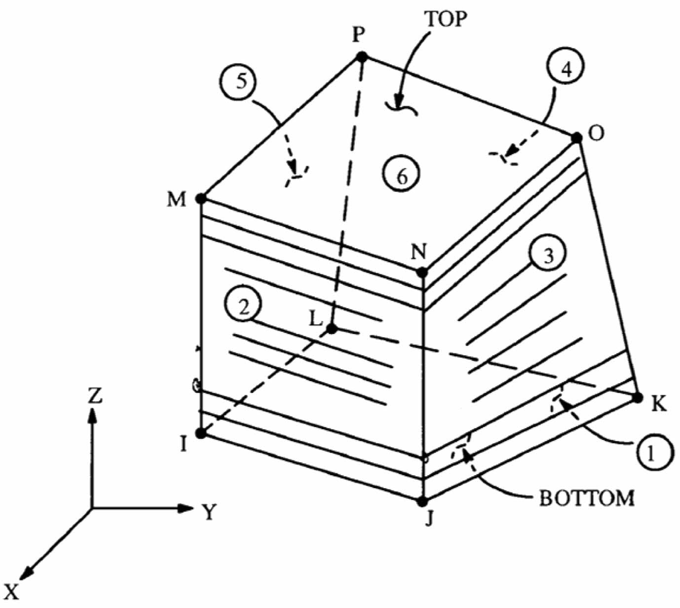
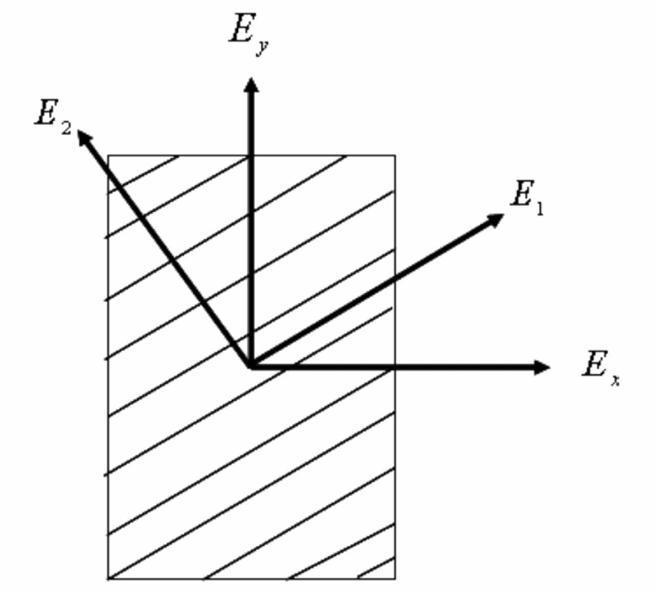
Solid186, layered solid element was utilised for simulate FRP composites. This element supports up to 100 separate material layers, orthotropic material characteristics and each with its own orientation. Translations in nodal x, y, z directions and three degrees independence available in each node for solid186 element. Fig. 9 depicts coordinate system, the geometry and node positions. As composites are orthotropic materials, nine separate characteristics must be input: “shear modulus in three different directions (Gxy, Gyz, Gzx), elastic modulus in three different directions (EX, EY, EZ) and Poisson’s ratio in three different directions (xy, yz, zx)”. The orthotropic Material’s primary directions are depicted in Fig. 10.
· Implied limitation and unfounded presupposition
· No elements may have a volume of zero, and element ordering may follow the conventions established in SOLID186 Geometry or be inverted so that planes IJKL, MNOP are inverted.
· The substance cannot be bent in a way that creates two separate volumes. The most common cause of this is incorrect piece numbering; each component needs to have eight nodes.
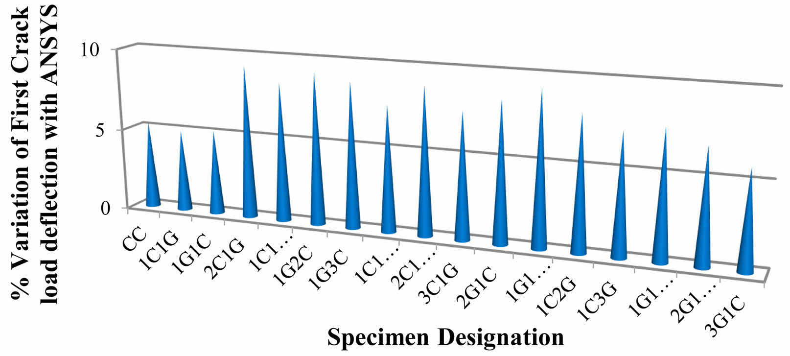
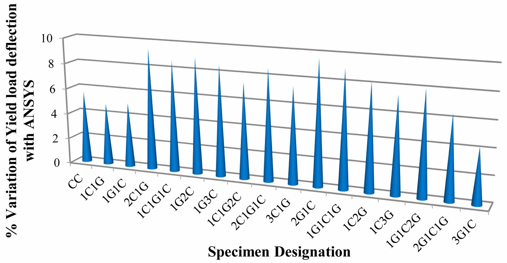
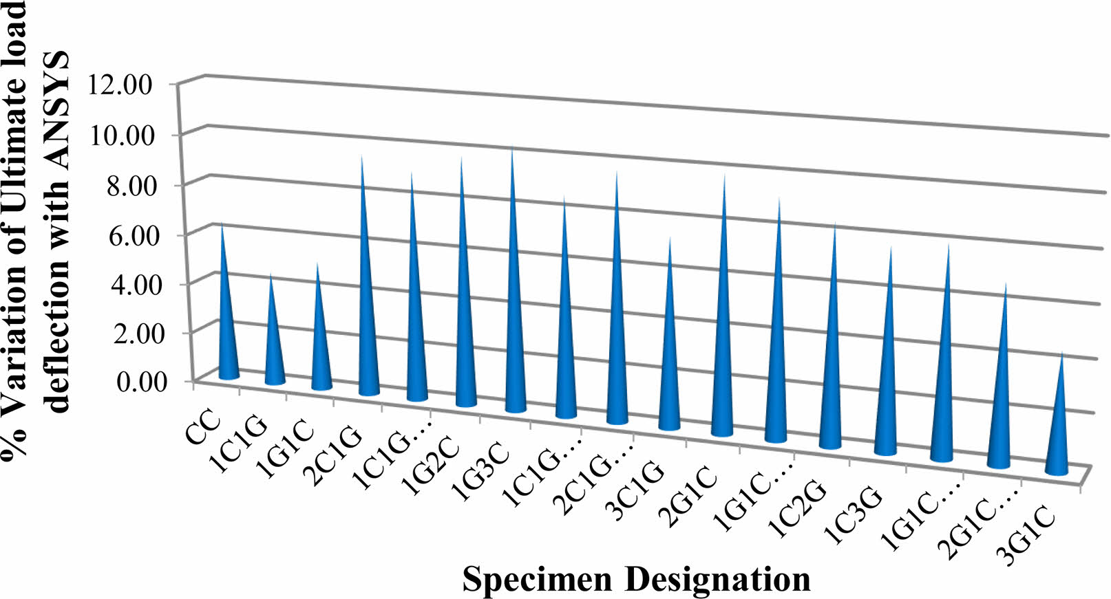
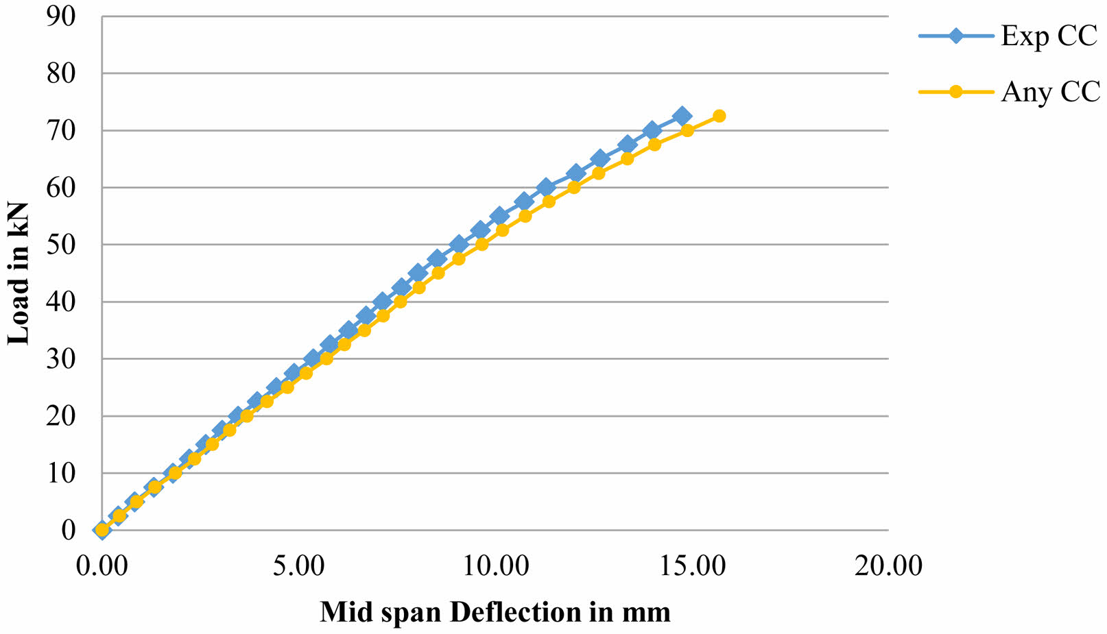
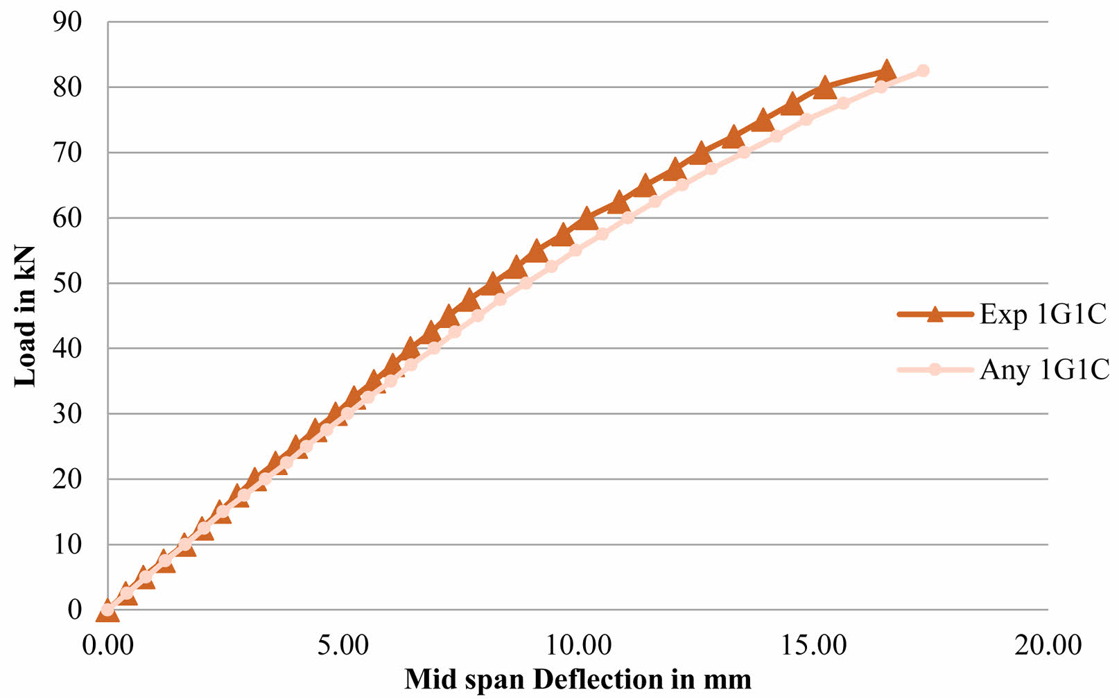
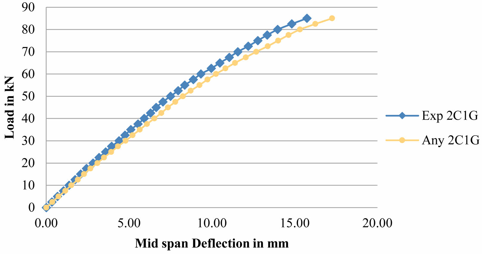
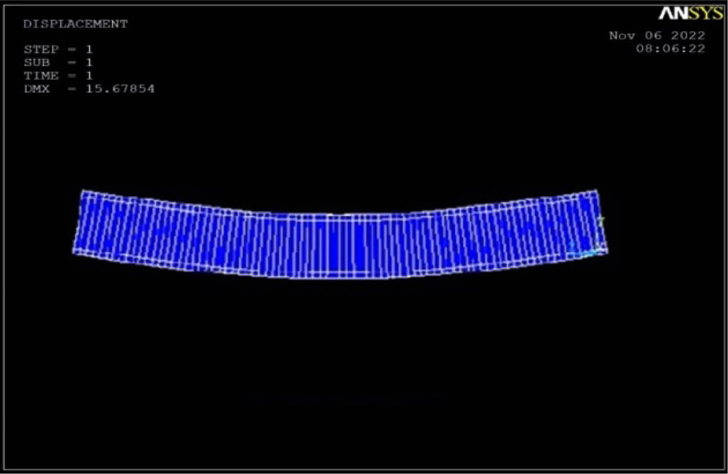
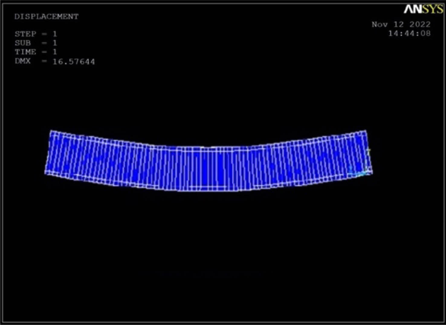
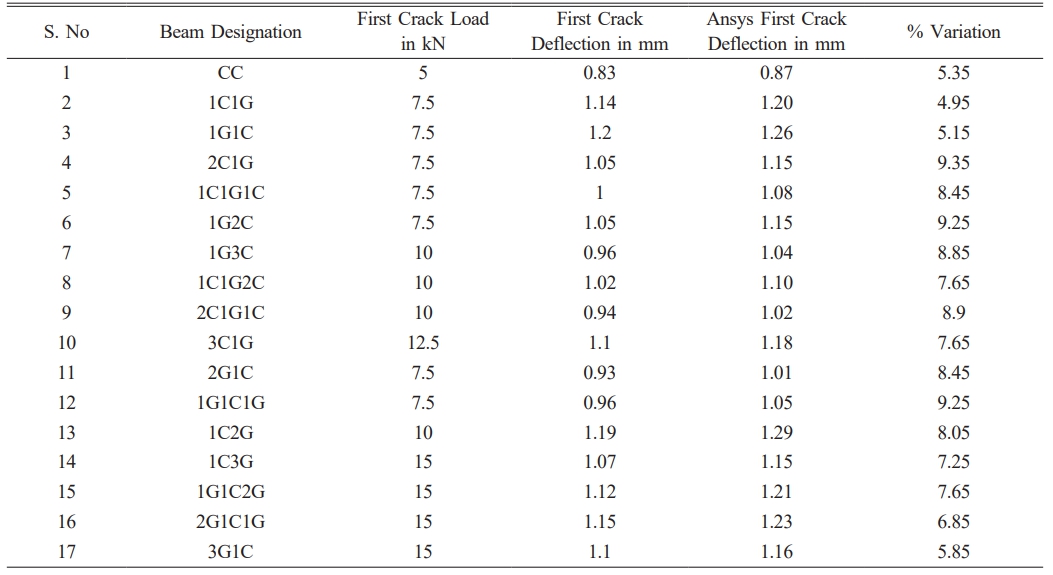
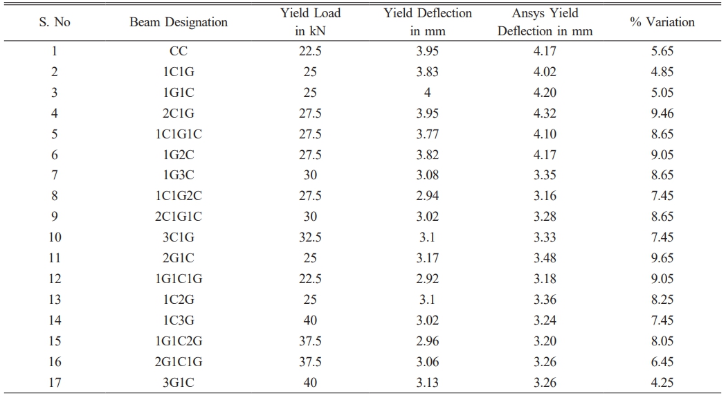
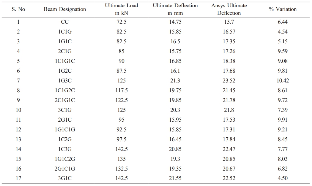
Fig. 11 shows % Variation of Deflection at First Crack Load, Fig. 12 shows % Variation of Deflection at Yield Load and Fig. 13 shows % Variation of Deflection at Ultimate Load.Fig. 14 Load Deflection Response of CC Beams Fig. 15 shows Load Deflection Response of 1G1C Beams Fig. 16 shows Load Deflection Response of 2C1G Beams Fig. 17 shows ANSYS Results on CC Beam Fig. 18 showsANSYS Results on 1C1G Beam. Table 7, 8, 9, 10, 11
|
Fig. 5 Solid 65 Element (3-D Reinforced Concrete Solid). |
|
Fig. 6 Link 180 Element. |
|
Fig. 7 Stress-Strain Curve for Steel Reinforcement. |
|
Fig. 8 Simplified Compressive Uni-axial Stress-Strain Curve for Concrete. |
|
Fig. 9 Solid186 3-D Layered Structural Solid. |
|
Fig. 10 Principal Directions of an Orthotropic Material. |
|
Fig. 11 % Variation of Deflection at First Crack Load. |
|
Fig. 12 % Variation of Deflection at Yield Load. |
|
Fig. 13 % Variation of Deflection at Ultimate Load. |
|
Fig. 14 Load Deflection Response of CC Beams |
|
Fig. 15 Load Deflection Response of 1G1C Beams. |
|
Fig. 16 Load Deflection Response of 2C1G Beams. |
|
Fig. 17 ANSYS Results on CC Beam. |
|
Fig. 18 ANSYS Results on 1C1G Beam. |
As compared to CC beam, the four layer hybrid FRP laminated reinforced concrete beam 1C3G exhibits maximum decrease in deflection at ultimate load of 57.80%. From above conclusion, the four layer of hybrid FRP laminated reinforced concrete beam 3G1C display the most effective in both deflection load and ultimate load. Each specimen of a beam contained flexural cracks. The suggested cracks were largely in the constant moment area. The reduction in crack width and number of cracks was found to be 300% and 380% at ultimate load level for four layer of 3G1C hybrid fibre reinforced polymer laminated reinforced concrete beam when compared with the CC. The average spacing of cracks decreased to 57.8% at ultimate load level for hybrid fibre reinforced polymer laminated reinforced concrete beam when compared with the CC.The findings of ANSYS-based tests results were well correlated with the outcomes of the experimental test results. The non-linear finite element modelling employed for research of CC RC beam and hybrid fibre reinforced polymer laminated RC beam proven that an effective prediction method. The predictions produced using ANSYS coincide fairly well with the findings of the trials.
- 1. A.M.I. Said and N. H. Tu’ma, Earth Environ. Sci. 856 (2021) 1-8.
-

- 2. A.S. Karzad, S.A. Toubat, M. Maalej and P. Estephane, MATEC Web Conf.120 (2017) 1-10.
-

- 3. M.M. Ahmed, O.A. Farghal, A. K Nagah. and Haridy, J. Eng. Sci. 35[3] (2007) 617-633.
-

- 4. J.A.O. Barros. and Fortes, Cem. Concr. Compos. 27 (2005) 471-480.
-

- 5. A. Bukhari, R. L.Vollum, S. Ahmad and J. Sagaseta, Mag. Concr. Res. 62[1] (2010) 65-77.
-

- 6. L.F.A. Bernardo and S. M. R. Lopes, J. Struct. Eng. 130 (2004) 452-459.
-

- 7. C. Yalburgimath, A. Rathod and S. Bhavanishankar, Int. Res. J. Eng. Technol. 5[10] (2018) 362-367.
- 8. E. Ahmed, H. R. Sobuz and N. M. Sutan, Int. J. Phys. Sci. 6[9] (2011) 2229-2238.
- 9. T.K. Gopinathan, P. N Raghunath and K. Suguna, Ind. J. Sci. Technol. 9[13] (2016) 1-7.
- 10. H.R.A. Baglo and M. Raoof, Adv. Mater. Res. 446-449 (2012) 718-727.
-

- 11. M.H. Kh, M. Ozakçab and T. Ekmekyapar, J. Adv. Res. Appl. Mech. 22[1] (2016)13-48.
- 12. M.I. Khan and W. Abbass, Constr. Build. Mater. 125 (2016) 927-935.
-

- 13. J. Josy and M.A. Johny, Int. Res. J. Eng. Technol. 6[5] (2019) 4348-4353
- 14. J. Karthick, K. Suguna and P. N. Raghunath, Ind. J. Sci. Technol. 10[11] (2017) 1-10.
-

- 15. A.K.H. Kwan, S.L. Chau and F.T.K Au, Proc. Inst. Civ. Eng. Struct. Build. 159[6] (2006) 339-347.
-

- 16. M. Mariappan, P.N. Raghunath and M. Sivaraja, Braz. Arch. Biol. and Techno. 59[2] (2016) 1-12.
-

- 17. M.M. Onal, Adv. Mater. Sci. Eng. 967964 (2014) 1-8.
-

- 18. A.M. Mashrei, S. J. Makki and A. A. Sultan, Lat. Am. J. Solids Struct. 16[4] (2019) 1-13.
- 19. N.S. Muhammad and H. N. Elbasha, Constr. Build. Mater. 21 (2007) 269-276.
- 20. N. Kabashi, B. Avdyli, E. Krasniqi and A. Kepuska, Civ. Eng. J. 6[1] (2020) 50-59.
-

- 21. N. Salleh, A. R. M.Sam, J. M. Yatim and M. F. B. Osman, Adv. Mater. Res. 1051 (2014) 748-751.
-

- 22. H.J. Pam, A.K.H. Kwan and M. S Islam, Proc. Inst. Civ. Eng. Struct. Build. 146[4] (2001) 381-389.
-

- 23. N. Pannirselvam, V. Nagaradjane and K. Chandramouli, ARPN J. Eng. Appl. Sci. 4[9] (2009) 34-39.
- 24. B. Parthiban K. Suguna and P. N. Raghunath, Asian J. Eng. Technol. 2[5] (2014) 415-423.
- 25. R. Rajeshguna, K. Suguna and P. N Raghunath, Int. J. Eng Sci. Innov. Technol. 3[4] (2014) 696-705.
- 26. R.S. Ravichandran, K. Suguna and P.N. Raghunath, Int. J. Adv. Eng. Res. Dev. 5[8] (2018) 135-138.
- 27. R. Thamrin, Z. Zaidir and D. Iwanda, Poly. 14[5] (2022) 1-31.
-

- 28. V.R.A. Saathappan, P.N. Raghunath and K. Suguna, J. Reinf. Plast. Compos. 30[24] (2011) 2015-2023.
-

- 29. S. Bastina and M. Renganathan, Int. J. Eng. Res. Technol. 6[7] (2018) 1-5.
- 30. S. Shrivastava and A. Tiwari, Int. J. Eng. Develop. Res. 6[3] (2018) 231-239.
- 31. S.A. Ashour, Eng. Struct. 22[5] (2000) 413-423.
-

- 32. S.H. Hashemi, A.A. Maghsoudi and R. Raghozar, Kuwait. J. Sci. Eng. 36[1] (2009) 1-31.
- 33. D.N. Shinde, M.P. Yojana, and V.N. Veena, Int. J. Res. Eng. and Technol. 3[3] (2014) 760-763.
- 34. S.P. Chiew, Q.Sun and Y. Yu, J. Compos. Constr. 11 (2007) 497-506.
-

- 35. S. Sivasankar, T. Bharathy and R.V. Kumar, Int. J. Eng Technol. 7[3.12] (2018) 744-749.
-

- 36. S.J. Raj, J.V. Vinay and H. Birhanu, Int. J. Eng. Res. Technol. 4[2] (2015)744-749.
- 37. N. Sundar, P.N. Raghunath and G. Dhinakaran, Int. J. Civil Eng. Technol. 7[6] (2016) 427-433.
- 38. S.S. Ibrahim, S. Eswari, and T. Sundararajan, Struct. Eng. Mech. 66[5] (2018). 631-636.
- 39. T. Selvi, P.B. Sakthivel and R.P. Gandhi, Int. J. Eng. Technol. 7[3.34] (2018) 30-35.
-

- 40. K.R. Venkatesan, P.N. Raghunath and K. Suguna, Int. J. Eng. Sci. Innov. Technol. 4[1] (2015) 135-140.
- 41. W. Wenwei and L. Guo, J. Wuhan. Univ. Technol. - Mater. Sci. Ed. 21[3] (2006) 82-85.
-

 This Article
-
2024; 25(6): 1105-1114
Published on Dec 31, 2024
- 10.36410/jcpr.2024.25.6.1105
- Received on Jul 29, 2024
- Revised on Sep 24, 2024
- Accepted on Oct 24, 2024
 Services
Shared
 Correspondence to
- P. Somiyadevi
-
Assistant Professor, Department of Civil Engineering, Adhiparasakthi Engineering College, Melmaruvathur, Tamil Nadu, India-603319
Tel : 9445446867 - E-mail: somiya86@gmail.com




 Copyright 2019 International Orgranization for Ceramic Processing. All rights reserved.