


- Structural and magnetic properties of Ce4+-substituted W-type strontium ferrites
Jinsong Li, Xiubin Zhao and Ailin Xia*
Advanced Ceramics Research Center, School of Materials Science and Engineering, Anhui University of Technology, Maanshan, 243032, China
This article is an open access article distributed under the terms of the Creative Commons Attribution Non-Commercial License (http://creativecommons.org/licenses/by-nc/4.0) which permits unrestricted non-commercial use, distribution, and reproduction in any medium, provided the original work is properly cited.
Ce4+-substituted strontium W-type hexagonal ferrites Sr1-xCexZn1.4Ni0.6Fe16O27 (x = 0.00 to 0.30 with steps of 0.06) have been prepared using a solid-state method. The XRD patterns of specimens exhibit a single-phase W-type crystalline structure. The particles show a hexagonal flake shape. The saturation magnetization slightly decreases for x < 0.12 and then increases significantly for x > 0.12, which is opposite to the change of coercivity. The initial magnetic permeability shows a significant increase due to the effect of the saturation magnetization and the grain size of specimens.
Keywords: W-type ferrite, Solid-state method, Magnetic properties, Initial permeability.
Magnetic material is an indispensable fundamental electronic functional material, which is generally categorized into permanent magnets (hard magnets) and soft magnets. It is widely studied due to the current and prospective applications in the fields of communication, new energy, automobiles, cloud computing, lighting, IT, home appliances, industrial automation, healthcare, military and so on [1, 2]. It has been demonstrated that the coercivity (Hc), the initial magnetic permeability (μi) and the saturation magnetization (Ms) can be controlled by the univalent or bivalent ion substitution to obtain the desired electromagnetic properties [3-7].
The chemical formula of W-type ferrite is AMe2Fe16O27, which belongs to the hexagonal crystal system. The space group is P63/mmc(194). The crystal structure can be considered as the stacking of so-called R blocks and S blocks along c axe in the order of SSRS*S*R* [8, 9]. Magnetic Fe3+ ions occupy seven different crystal sites in the W-type hexagonal crystal structure, respectively [10].
In order to achieve modification of metal ions, different synthesis processes have been used to prepare W-type ferrites. The ceramic (solid-state) and sol-gel methods are widely adopted due to its simple process and low cost [11]. Tang et al. [12] prepared Sr1−xLaxFe22+Fe163+O27 W-type ferrites by a ceramic method. The XRD results confirmed a pure hexagonal crystal structure. The lattice constant a of the samples did not change greatly. However, the lattice constant c decreased with the increasing doped amount. Niu et al. [13] investigated La-doped W-type ferrites Sr1-xLaxCo2Fe16O27 prepared by a ceramic method. The Hc of specimens increased with increasing La content, and the Ms of particles first increased with x from 0 to 0.15 and then began to decrease.
It has been reported that the Ce substitution can tailor the magnetic properties of M-type SrFe12O19 ferrites.
Cao et al. [14] prepared hexagonal M-type ferrites SrCexFe12-xO19 via a ceramic method. Single phase M-type ferrite with no impurities was obtained when the substitution amount x was less than 0.04. It was found that the Ce substitution can improve the Ms and the Hc to a certain extent. Sadiq et al. [15] prepared W-type ferrite with the chemical formula Sr3-xCexFe16O27 (x is from 0.00 to 0.10 with steps of 0.02) by a sol-gel method. With the doping of rare earth Ce3+ ions, the Hc of samples first increased but then decreased, while the Ms shows a wave-like increasing trend.
However, up to the authors’ knowledge, the effect of Ce4+-substituted W-type hexagonal strontium ferrites was still not been reported. Therefore, Ce4+ substituted W-type hexagonal strontium hexagonal ferrites Sr1-xCexZn1.4Ni0.6Fe16O27 have been prepared using a solid-state method in this study. The influences of CeO2 content (x) on the microstructure and magnetic properties of W-type ferrite were investigated.
Materials
Ferric oxide (Fe2O3, 99.2% purity), strontium carbonate (SrCO3, 98% purity), cerium oxide (CeO2, 99% purity), zinc oxide (ZnO, 99% purity) and nickel oxide (NiO, 99% purity) powders without further purification were used as raw materials.
Preparation of W-type ferrites Sr1-xCexZn1.4Ni0.6Fe16O27 powders
The specimens of Sr1-xCexZn1.4Ni0.6Fe16O27 (x is from 0.00 to 0.30 with the steps of 0.06.) were synthesized by a solid-state method. The raw materials, weighed stoichiometrically to prepare specimens of 150 grams, were milled in purified water for 4 hours in an experimental ball mill. The milled slurry was dried, pressed into small pieces, and placed in a muffle furnace to be calcinated at 1320 ℃ for 2 hours in the air. After calcination the fragments were shaken to a powder and sieved through a 100 mesh sieve. The obtained powders with 3 wt.% polyvinyl alcohol solution (PVA) were stirred to homogeneity and pressed into ring specimens, which were sintered at 1200 ℃ for 2 hours in the air and used for the measurement of permeability.
Characterization
The phase composition of specimens was analyzed by an XRD diffractometer using Cu Kα radiation (X'Pert Pro, λ=1.5406 Å). The scanning range was determined to be 20° - 80° in a step of 0.01°. The morphology of all specimens was obtained by a field emission scanning electron microscope (FESEM, HITACHI S-4800). The magnetic properties were measured at room temperature (RT) by a vibrating sample magnetometer (VSM, MicroSense EZ7) with a maximum external magnetic field of 20,000 Oe. The permeability of these specimens was measured by a digital bridge meter (Agilent 4284A) at the frequency of 1 MHz at room temperature.
Structure and morphology
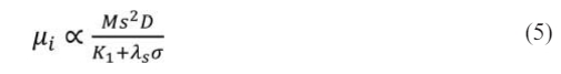
Fig. 1 shows the XRD patterns of Sr1-xCexZn1.4Ni0.6Fe16O27 specimens. Compared with the standard JCPDS card (PDF # 75-0406), all the XRD patterns reveal a typical single-phase magnetoplumbite structure without any impurity. Therefore, seen from Fig. 1, no impurity phase was found after the substitution of Ce4+ ions.
The characteristic peaks (116) and (1010) of W-type ferrite were determined in Fig. 1. Based on the corresponding values of dhkl of the peaks, the lattice parameters a and c of all the specimens can be calculated using the following formula (1) and (2) [16, 17]:
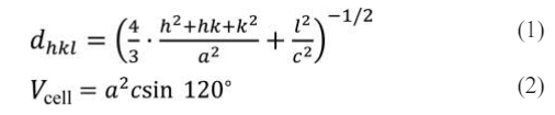
The crystal planner distance (dhkl) and cell volume (Vcell) are denoted here, respectively. The Miller indices in the XRD patterns are denoted by the parameters h, k, and l, while the associated lattice constants are a and c. The X-ray density (dX-ray) and average crystallite size (D) were obtained by the following equations (3) and (4) [18, 19]:
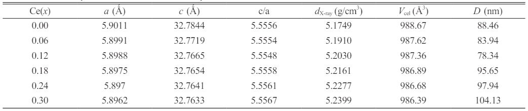
where M stands for the molar mass of the related specimens, β for the Bragg's diffraction angle, and b for the whole width at half-maximum. NA, K and λ are 6.02×10²³, 0.89 and 1.5406 Å, respectively. The corresponding parameters of all the specimens were calculated and listed in Table 1.
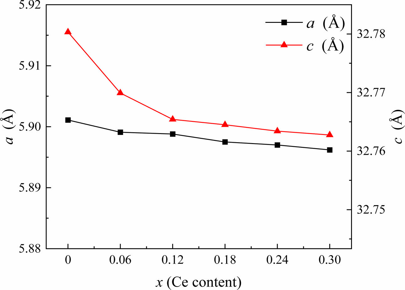
The variations in the crystalline parameters (a and c) of specimens with varying x are displayed in Fig. 2. As x grows from 0.00 to 0.30, the lattice parameter c reduces dramatically while the lattice parameter a changes somewhat due to the substitution of Ce4+ ions for Sr2+ ions. The early literature has also reported on the modifications in lattice properties brought about by ion replacement [20-23]. Ce4+ caused the change of lattice parameters a and c in substituted specimens, mainly due to the difference in ionic radius (r) of substituted metal ions. When Sr2+ (r =1.180 Å) is replaced by Ce4+ (r =0.990 Å), a negative ionic radius difference is generated [15]. While based on the ion charge balance relationship, some Fe3+ ions (r=0.645 Å) will converted into Fe2+ ions (r =0.780 Å), resulting in a positive ionic radius difference. Because the C-axis is the easily magnetized axis of W-type ferrite, spin rotation is more likely to occur along the base plane perpendicular to the C-axis [24]. Therefore, the lattice constant c will undergo significant changes compared with the lattice constant a. All of these are ultimately reflected in the changes of lattice parameters, as shown in Fig. 2. The change of lattice parameter a is relatively small, while c shows a decreasing trend with increasing x, and the cell volume of the substitution specimens shows a decreasing trend compared with the unsubstituted specimen.
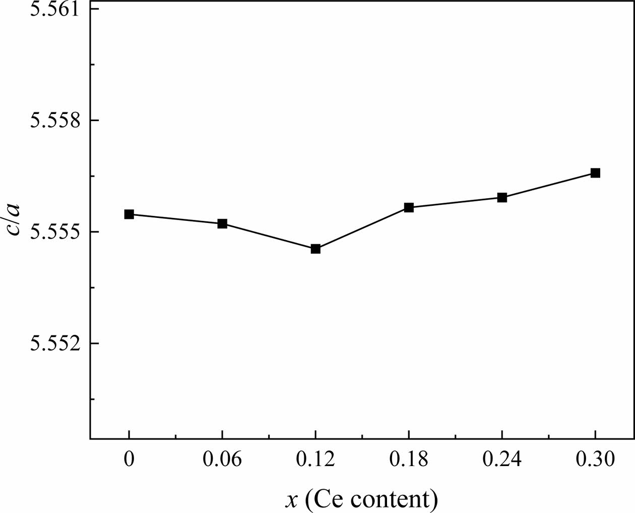
Wagner [25] mentioned that the c/a value of W-type hexagonal ferrites is less than 5.585, which conforms to the lattice structure characteristic of W-type ferrites. In this study, the ratios c/a of all the specimens are listed in Table 1. Fig. 3 shows the dependency of c/a on x. With different x, the ratio of c/a ranges from 5.5548 to 5.5567, which is consistent with the characteristic value of the W-type structure described above.
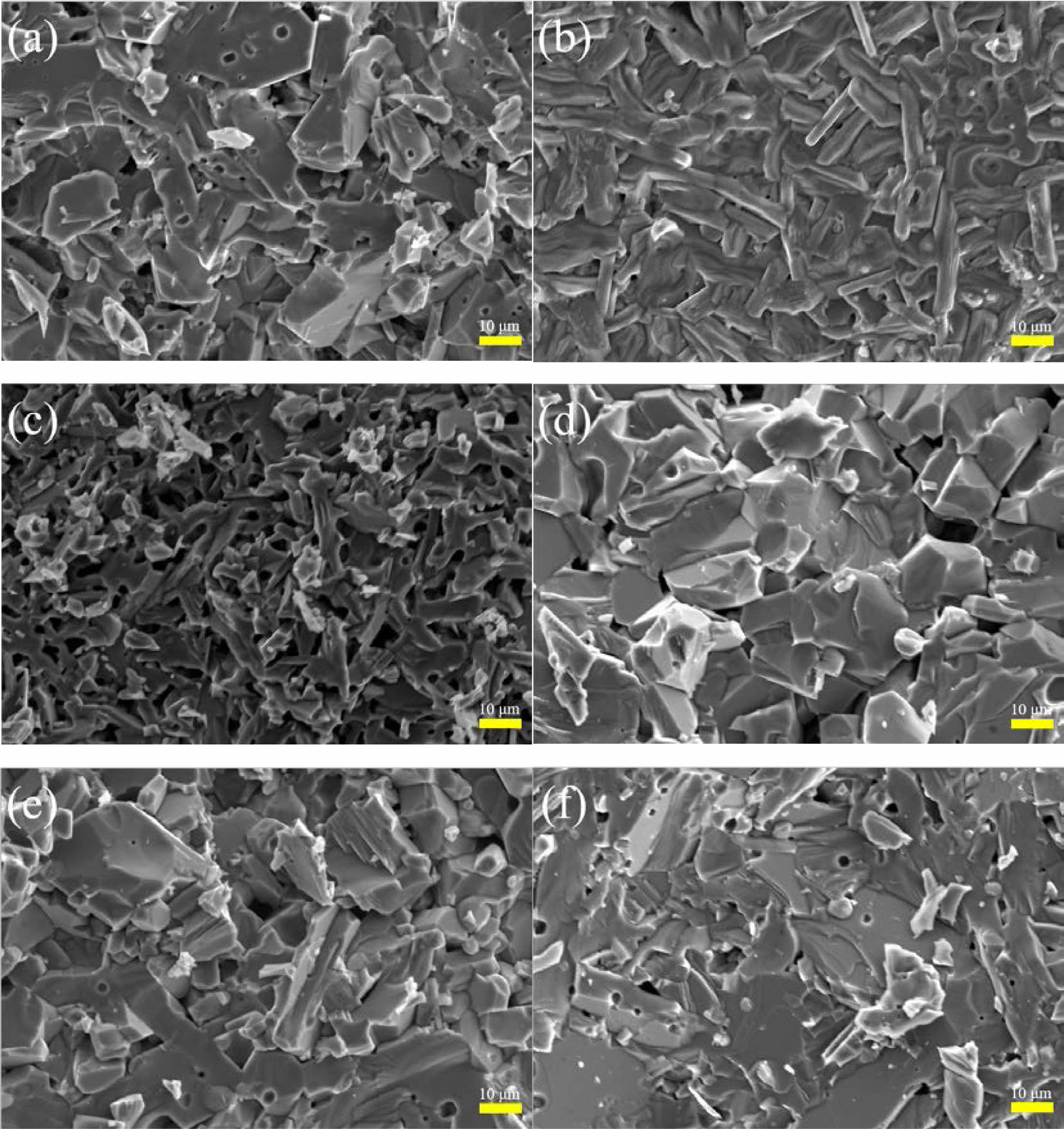
Fig. 4 shows the microstructure of Sr1-xCexZn1.4Ni0.6Fe16O27 specimens with different x. It can be seen that a flake structure has been formed in Fig. 4(a) and (d)~(f), which consists with the reported morphology of W-type hexagonal ferrites [8]. The grain shape in Fig. 4(b) and (c) is elongated and more voids are present. For x < 0.12 and x > 0.12, the grain size exhibits a decreasing and increasing tendency with the increasing of Ce4+ substitution (x), respectively.
Magnetic properties
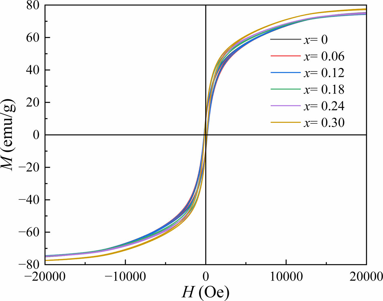
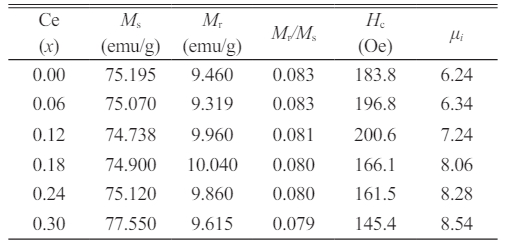
The RT magnetic hysteresis loops of the Sr1-xCexZn1.4Ni0.6Fe16O27 specimens are displayed in Fig. 5. The values of Ms, Hc, remanence magnetization (Mr) and square ratio (Mr/Ms) were obtained through the RT magnetic hysteresis loops and listed in Table 2. It should be noted out that under a magnetic field of 20 kOe, the measured hysteresis loops approach saturation, so the values of Ms was obtained at 20 kOe.
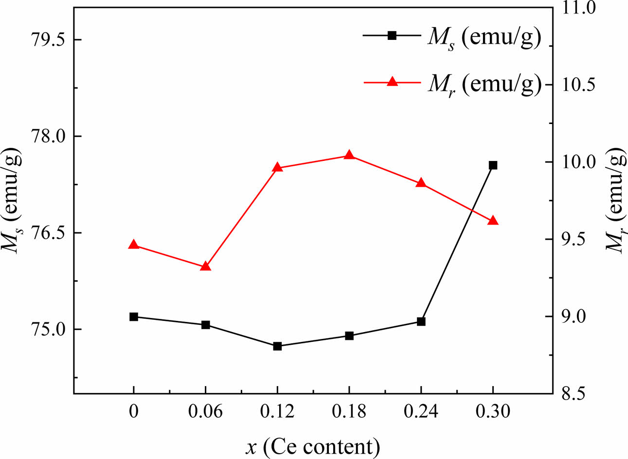
In this study, as shown in Table 2 and Fig. 6, the Ms of specimens decreases first and then increases as x increases. It reaches the minimum value at x = 0.12. The Mr fluctuates and reaches the maximum at x = 0.18. The following reasons caused these changes. Firstly, when Sr2+ ions were replaced by Ce4+ ions in the specimens, in order to achieve an equilibrium of excessive positive charges, some Fe3+ ions were converted into Fe2+ ions. As is well known, since the magnetic moment of Fe3+ and Fe2+ is 5.0 μB and 4.0 μB, respectively, the net magnetic moment will decrease [2, 26], which causes the decrease of Ms in Sr1-xCexZn1.4Ni0.6Fe16O27 (0 ≤ x ≤ 0.12) specimens. However, for the specimens with x > 0.12, there are two reasons for the significant increase in Ms. On the one hand, the smaller Ce4+ ions replaced some Sr2+ ions, and the lattice parameter c decreased, as shown in Fig. 2. An increased super-exchange interaction resulted from the corresponding reduction in the distance of Fe-O bonds parallel to the c-axis [27]. On the other hand, with the increasing content of Ce4+ (x), the internal stress caused by the lattice distortion enhanced the magnetic interaction in the sublattice [28-30]. Therefore, combined the above two factors, a significant increase of Ms can be found in the specimens. In this study, the squareness ratios (Mr/Ms) of magnetic hysteresis loops for all the specimens were calculated and listed in Table 2. It can be observed that the square ratio is between 0.079 and 0.083. A squareness ratio of greater or less than 0.5 indicates a single or multiple magnetic domain structure in the specimens, respectively [31]. Therefore, all the specimens in this study show the multiple magnetic domain structure.
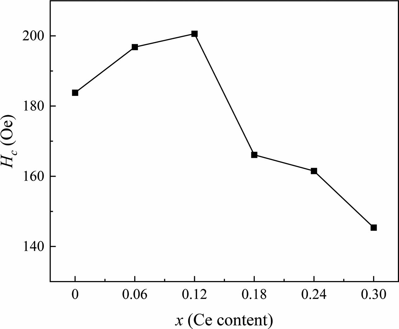
The changes in Ms, Mr and Hc are similar to the previous literature [32, 33]. The Hc of specimens as shown in Fig. 7 increases between x =0 and 0.12, while remains a decreasing trend for x > 0.12. When x ≤ 0.12, the symmetry of the crystal decreases after the Ce4+ substitution due to the smaller radius of Ce4+ ion compared with that of Sr2+ ions. The crystal with low symmetry has a strong magnetocrystalline anisotropy, which causes the increase of Hc accordingly [34]. Table 1 shows that the grain size progressively rises when x > 0.12 as x increases. It was reported that the Hc is mostly affected by the grain size of specimens [31]. Usually, the Hc has an inverse relationship to the grain size greater than the single domain critical size (Dc), which was estimated to be 650 nm for SrM ferrite [35]. In this study, it can be seen from Fig. 7 and Table 1 that for x < 0.12 and x > 0.12, the change of Hc is consistent with the change of grain size described above (Fig. 4).
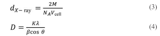
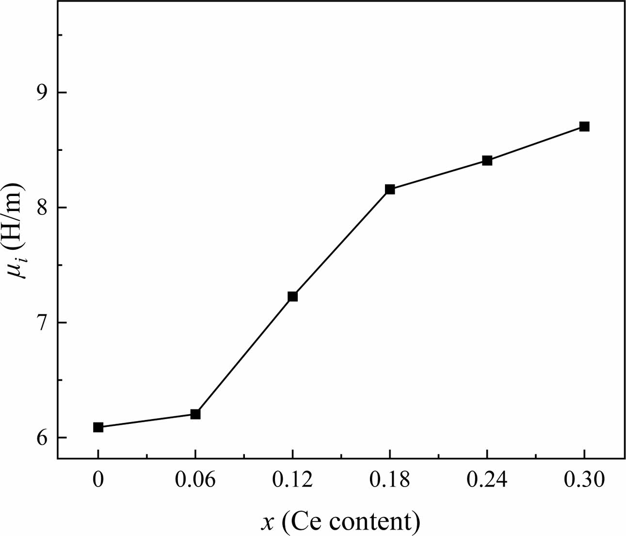
Fig. 8 shows the ui of specimens measured at 1 MHz, which increases from 6.24 to 8.54 for x = 0 to 0.30. Generally, the ui of ferrite is affected by the Ms and the magnetocrystalline anisotropy constant (K1), as shown in the following formula [36]:
where D, λs and σ are the average crystallite size, the magnetostriction coefficient and the internal stress, respectively. In this study, the effect of λS and σ can be ignored due to the low internal stress of ferrite materials [37]. Meanwhile, the magnetocrystalline anisotropy of all specimens is also slightly affected by the amount of Ce4+ substitution. Therefore, Ms and D are the dominant factors for the value of ui. As the D increases, the blocking effect of grain boundaries on the domain wall displacement decreases, and thus the value of ui increases. From Table 1 and Fig. 6, it can be seen that as x increases, D and Ms first decrease (x < 0.12) and then increase (x > 0.12). However, it is observed that ui increases as x increases in Fig. 8. It may be caused by the fact that when x = 0.06 and x = 0.12, the grains are elongated and have more voids which makes σ larger Therefore, as the Ce4+ substitution amount increases, the ui value shows a significant increase.
|
Fig. 1 The XRD patterns of Sr1-xCexZn1.4Ni0.6Fe16O27 specimens with different x. |
|
Fig. 2 The change of lattice constants a and c of Sr1-xCexZn1.4Ni0.6Fe16O27 specimens with different x. |
|
Fig. 3 The change c/a of Sr1-xCexZn1.4Ni0.6Fe16O27 specimens with different x. |
|
Fig. 4 Typical FE-SEM images of Sr1-xCexZn1.4Ni0.6Fe16O27 specimens with different x. (a-f): x is from 0.00 to 0.30 with steps of 0.06, respectively. |
|
Fig. 5 RT magnetic hysteresis loops of Sr1-xCexZn1.4Ni0.6Fe16O27 specimens with different x. |
|
Fig. 6 The Ms and Mr of Sr1-xCexZn1.4Ni0.6Fe16O27 specimens with different x. |
|
Fig. 7 The Hc of Sr1-xCexZn1.4Ni0.6Fe16O27 specimens with different x. |
|
Fig. 8 The ui of Sr1-xCexZn1.4Ni0.6Fe16O27 specimens with different x. |
Solid-state technique was used to create Ce4+ substituted strontium W-type ferrites Sr1-xCexZn1.4Ni0.6Fe16O27 (x is from 0.00 to 0.30 with steps of 0.06.). All specimens have a single W-phase hexagonal crystal structure. The c/a ratio hardly varies as x increases, while the lattice parameters of a and c indicate a substantial drop. When x < 0.12 and x > 0.12, the Ms exhibits a decreasing and increasing tendency with the increasing of x, respectively, while it exhibits a completely opposite trend for the Hc. The ui of specimens shows a significant increase for 0 ≤ x ≤ 0.30.
Jinsong Li: Investigation, Methodology, Writing - original draft, Writing - review & editing, Funding acquisition. Xiubin Zhao: Writing - review & editing, Investigation, Formal analysis. Ailin Xia: Writing - review & editing, Funding acquisition, Methodology, Project administration, Supervision.
The authors declare that they have no known competing financial interests or personal relationships that could have appeared to influence the work reported in this paper.
Data will be made available on request.
- 1. M. Etier and H. Aimomani, J. Ceram. Process. Res. 21[5] (2020) 565-570.
-

- 2. Y.J. Yang, X.S. Liu, and S.J. Feng, J. Ceram. Process. Res. 21[3] (2020) 378-385.
-
- 3. X.G. Huang, J. Chen, and L. X. Wang, Rare Metals. 30[1] (2011) 44-48.
-
- 4. X.B. Zhao and A.L. Xia, J. Ceram. Process. Res. 24[4] (2023) 634-639.
-
- 5. Y.M. Zhang, Y.J. Yang, D.Y. Chen, C.L. Chen, and Y.T. Meng, J. Ceram. Process. Res. 24[2] (2023) 342-347.
-
- 6. X.B. Zhao, S. Zhang, J.S. Li, A.L. Xia, and Y.J. Yang, J. Ceram. Process. Res. 24[1] (2023) 98-102.
-
- 7. T. Mariam, I.N. Esha, M.N. Khan, S. Choudhury, and K.H. Maria, J. Ceram. Process. Res. 21[4] (2020) 442-449.
-
- 8. L.W. Deng, L. Ding, K.S. Zhou, S.X. Huang, Z.W. Hu, and B.C. Yang, J. Magn. Magn. Mater. 323 (2011) 1895-1898
-
- 9. Y.J. Yang, C.L. Chen, and D.Y. Chen, Magnetochemistry. 8 (2022) 75.
-
- 10. J.S. Li, X.B. Zhao, and A.L. Xia, J. Ceram. Process. Res. 24[5] (2023) 894-898.
-
- 11. J. Tang, D. Li, H. He, Y.M. Li, J.S. Zeng, and C. Liu, J. Appl. Phys. A 126[4] (2020) 277.
-
- 12. J. Tang, X.S. Liu, D. Li, and Y.J. Yang, J. Mater. Sci.: Mater. Electron. 30 (2019) 284-291.
-
- 13. X.F. Niu, Y. Liu, M. Li, B. Wu, and H. Li, J. Electron. Mater 46 (2017) 4299-4303.
-
- 14. C.X. Cao, X. Li, B.Y. Luo, Y. Li, A.J. Zhang, and A.L. Xia, J. Supercond. Nov. Magn. 31[4] (2018) 1247-1251.
-
- 15. I. Sadiq, I. Khan, F. Aen, M.U. Islam, and M.U. Rana, Physica B: Condensed Matter. 407 (2012) 1256-1261.
-
- 16. X. Niu, X. Liu, S. Feng, F. Lv, F. Huang, X. Huang, Y. Ma, and K. Huang, Optik. 126[24] (2015) 5513-5516.
-
- 17. M.N. Akhtar, K. Ali, A. Umer, T. Ahmad, and M.A. Khan, Mater. Res. Bull. 101 (2018) 48-55.
-
- 18. M.J. Iqbal and R.A. Khan, J. Alloy. Compd. 478 (2009) 847-852
-
- 19. M.J. Iqbal and S. Farooq, J. Alloy. Compd. 505[2] (2010) 560-567
-
- 20. Y.F. Wu, Y. Huang, and L. Niu, J. Magn. Magn. Mater. 324 (2012) 616-621.
-
- 21. I. Khan, M.N. Ashiq, I. Sadiq, A.M. Qureshi, and M.U. Rana, J. Chem. Soc. Pakistan 34 (2012) 579-583.
-
- 22. M.J. Iqbal, R.A. Khan, S. Mizukami, and T. Miyazaki, Ceram. Int. 38 (2012) 4097-4103.
-
- 23. F. Leccabue, R. Panizzieri, G. Albanese, G. Leo, and N.S. Almodovar, Mater. Res. Bull. 23[2] (1988) 263-275.
-
- 24. F.K. Lotgering, P.H.G.M. Vromans, and M.A.H. Huyberts, J. Appl. Phys. 51[11] (1980) 5913-5918.
-
- 25. T.R. Wagner, Int. J. Quantum Chem. 136[1] (1998) 120-124.
- 26. F.R. Lv, X.S. Liu, and S.J. Feng, Mater. Lett. 157 (2015) 277-280.
-
- 27. J. Tang, X.S. Liu, D. Li, and Y.J. Yang, J. Mater. Sci.: Mater. Electron. 30 (2019) 284-291.
-
- 28. A.G. Abraham, A. Manikandan, E. Manikandan, S.K. Jaganathan, A. Baykal, and P.S. Renganathan, J. Nanoelectron. Optoelectron. 12 (2017) 1326-1333.
-
- 29. A.G. Abraham, A. Manikandan, E. Manikandan, S. Vadivel, S.K. Jaganathan, A. Baykal, P.S. Renganathan, and J. Nanoelectron, J. Magn. Magn. Mater. 452 (2018) 380-388.
-
- 30. R. Rajendran, R. Muralidharan, R.S. Gopalakrishnan, M. Chellamuthu, S.U. Ponnusamy, and E. Manikandan, Eur. J. Inorg. Chem. 2011[35] (2011) 5384-5389.
-
- 31. I. Khan, I. Sadiq, M. Ashiq, and M. Rana, J. Alloy. Compd. 509 (2011) 8042-8046.
-
- 32. G. Albanese, M. Carbucicchio, and G. Asti, J. Appl. Phys. 11[1] (1976) 81-88.
-
- 33. S. Ram and J.C. Joubert, J. Magn. Magn. Mater. 99 (1991) 133-144.
-
- 34. S. Ounnunkad, Solid State Commun. 138[9] (2006) 472-475.
-
- 35. A.L. Xia, S.Z. Ren, J.S. Lin, Y. Ma, C. Xu, J.L. Li, C.G. Jin, and X.G. Liu, J. Alloy. Compd. 653 (2015) 108-116.
-
- 36. H. Su, H. Zhang, X. Tang, B. Liu, and Z. Zhong, J. Alloy. Compd. 475[1] (2009) 683-685.
-
- 37. Y. Peng, X.H. Wu, Z.Y. Chen, W.H. Liu, F. Wang, Z.K. Feng, Y.J. Chen, and V.C. Harris, J. Alloys Compd. 630 (2015) 48-53.
-
 This Article
-
2024; 25(2): 316-321
Published on Apr 30, 2024
- 10.36410/jcpr.2024.25.2.316
- Received on Feb 21, 2024
- Revised on Mar 21, 2024
- Accepted on Mar 22, 2024
Services
- Abstract
introduction
experimental procedures
results and discussion
conclusions
- Author Contributions
- Conflict of Interest
- Data availability statement
- References
- Full Text PDF
Shared
Correspondence to
- Ailin Xia
-
Advanced Ceramics Research Center, School of Materials Science and Engineering, Anhui University of Technology, Maanshan, 243032, China
Tel : 86-0555-2311892 Fax: 86-0555-2311875 - E-mail: alxia@126.com
Clean-Energy Research Institute(CRI), Hanyang University, 222, Wangsimni-ro, Seongdong-gu, Seoul, 04763, Korea
E-mail: jcpr@hanyang.ac.kr