


- Design optimization and development of SMC composite tray
Cun-fei Wanga, Zeng-fu Yanga, Chengwang Shib, Xiaodong Lib and Xu-feng Zhangb,*
aChina Shenhua Energy Co., LTD. Shendong Coal Branch, Yulin 719325, China
bSchool of Materials Science and Engineering, Beijing Institute of Technology, Beijing 100081, ChinaThis article is an open access article distributed under the terms of the Creative Commons Attribution Non-Commercial License (http://creativecommons.org/licenses/by-nc/4.0) which permits unrestricted non-commercial use, distribution, and reproduction in any medium, provided the original work is properly cited.
In the engineering application, trays are easy to break down to result in anchorage failure in the composite anchoring systems. Therefore, the research carried out the force analysis with mechanics of materials to observe the main stress concentration and deformation of the tray. From the findings of the force analysis, the structure and key parameters of the tray were optimized with reference of the existing tray design. Besides, the study turns to the finite element software to simulate and analyze the tray. The results manifest that tray failure during the support mainly results from the expansion and deformation of the taper hole squeezed by the nut, which causes the tray taper hole to rupture and crackle extend, thus leading to its crack. What’s more, the tray breaks for the compression of the tray edge by the surrounding rock. The maximum deformation at the large end of the optimized tray tapered hole was reduced from 33.8 mm to 4.7 mm, approximately 86% with the shear stress reduced from 781.67 Mpa to 258.83 Mpa, about 66.8%. Using Sheet Molding Compound (SMC) to mould trays with new structure and conducting the test of tray bearing capacity, it can be found that its bearing capacity is up to 250 KN. After the taper hole of the tray is locally strengthened, its bearing capacity is increased to 304 KN.
Keywords: Composite tray, Tray failure, Numerical simulation, Bearing capacity, Crack.
Bolt support is recognized as an economical and effective way of coal lane support around the world which can significantly improve its support effect, greatly simplify the end support and lead support method. It provides conditions for rapid advancement of coal mining face, production and efficiency. Bolts are the main support of coal lane support and the conventional material is steel. However, steel bolts are susceptible to corrosion and failure in underground mine operations. Therefore, people are worried about the durability and the safety of steel bolts. In high gassy mines, once the steel bolts touch the cutting heads of the machine, it will strike a spark, causing gas explosion and spontaneous dust combustion. The accident can lead to a large number of casualties. Thus, the use of steel bolts has serious hazards [1-5]. Such being the case, the development of new bolts to replace the steel ones is of great importance. It makes great difference in ensuring safe operation and coal mining efficiency.
Compared with metal bolts, composite bolts have the potential advantage of replacing steel anchors due to their non-metallic nature, durability, light weight and low production costs [6-10]. As part of the composite bolting system, the tray sits at the end of the system connected with the surrounding rock. The preload nut presses the tray to the roadway surface under the action of torque, providing preload for the anchor. Besides, when the coal body is deformed, the load will concentrate on the tray, then the tray transfers the load to the bolt, increasing its working resistance. In this connection, it will inhibit the coal body looseness and further deformation. Tray failure and dislodgement of the surrounding rock beneath the trays will lead to the looseness between the tray and the surface. As such, the bolts will be invalid [11-16]. Therefore, the strength of the tray directly determines the stability of the bolting system. The reasonable structure and material are essential for bolt supporting technology.
The mechanical properties of the tray should be consistent with that of the bolts, giving full play to the function of the bolt. According to statistics, glass fibre reinforced composite bolts are commonly developed and used around the world. The trays used in the bolts are manufactured with short-cut fibre reinforced thermoplastic or thermosetting resins by injection or moulding. The strength of the short-cut fibre-reinforced composite is low, therefore, the trays tend to deform in practical application with the centre hole cracking or tray edge crushing. What’s more, the current structural design of the composite trays is unreasonable, further increasing the risk of anchor failure in the support sites. Zhao [17] carried out a simulation of the stress and strain distribution of the tray and nut under ultimate load, which is of great significance to the structural design and material selection of the tray. Li [18] analyzed the stress and strain distribution of trays under different loads as well as the mechanical equations by structural simplification, providing a theoretical basis for the design. However, the research is only limited to simulation and analysis, without improving the bearing strength and addressing problems in the field application through structural optimization and material design.
The thesis optimizes the structural parameters of the trays by force analysis and simulation to address the damage of the trays in the field application. The findings show that the optimization can improve the bearing capacity of the tray. The study uses fibre-reinforced composite to design the tray and adopts short-cut glass fibre and continuous fibre-reinforced SMC sheets. Reinforcing the local structure to mould the tray can obtain composite trays with high bearing strength.
Experimental materials
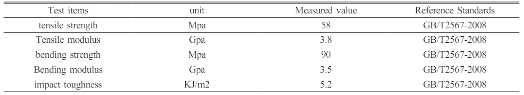
The independently developed sheet molding compound (SMC) is used for tray molding. The resin matrix is o-phenyl unsaturated polyester resin, light yellow transparent liquid, viscosity (25 ℃, 1200-1400 mPa.s), gel time (120 ℃, 98s), and thermal deformation temperature ≥ 118 ℃. The mechanical properties of matrix resin casting body are shown in Table 1. The reinforcing fiber in the SMC sheet is ECR22-2400-928 glass fiber yarn made by China Jushi Co., Ltd. The tensile strength of dipped yarn is 2500-2700 Mpa, and the tensile modulus is 81-83 GPa. SMC sheet is mainly composed of unsaturated resin, cross-linking agent, initiator, thickener, low shrinkage agent, filler and glass reinforced fiber. The proportion of organic resin components (including unsaturated resin, cross-linking agent, initiator and low shrinkage agent), glass fiber and inorganic components (including thickener and filler) is 3:4:3. The filler is calcium carbonate from Guangxi Huacao Calcium Carbonate Technology Co., Ltd., with particle size of 500 meshes and content ≥ 95%. SMC sheets of A01, A02 and A03 specifications were prepared according to different lengths of glass fibers.
Equipments and instruments
Four-column hydraulic press, LNGT, nominal force 10000kN, Nantong Gaoye Hydraulic Machine Limited Company; Bolt tray moulding shape with the homemade pattern, six cavities exist in one mould and they will be heated in oil bath; Microcomputer screen display hydraulic universal testing machine, the maximum force is 600KN. Jinan Zhongluchang Testing Machine Manufacturing Limited Company.
Moulding
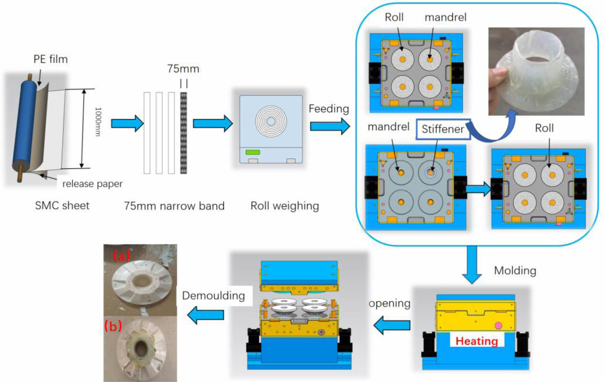
To begin with, the SMC sheet is cut into narrow strips with the width of 70±3 mm, the weight of 205±3 g. Then, it is rolled into a circle and put into the mould cavity, with the mandrel placing in the centre of the circle. The press machine closes the mould with the holding pressure maintaining 300 KN. After being insulated in 150±5 ℃ for 10 min, we can take out the mould and remove the flashs. In this way, the finished product is obtained. In order to effectively increase the bearing capacity of the taper hole of the tray, we take advantage of s-glass fibre prepreg to prefabricate a reinforced insert for the central hole of the tray, as shown in the Fig. 1. The thickness of the insert is 2 mm and the tapered hole is affixed at the top and bottom. The tapered hole insert is first placed on the tray mandrel in the mould cavity followed by placing SMC. Afterwards, we adopt the processing technology mentioned above to press them into shape. The moulding processes of the two trays with different structures are shown in Fig. 1.
Tray bearing capacity test
The tray bearing capacity test is carried out with reference to MT/T 1061-2008 standard, with the loading force at a rate of 3 kN/s. The tensile properties, bending properties and impact toughness of SMC sheets are tested based on GB/T2567-2008.
|
Fig. 1 Diagram of tray processing (a) plain tray (b) tapered hole reinforced pallet. |
Force analysis of composite trays
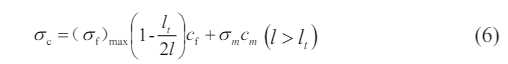
The composite bolting system consists of a bolt, a tray and a nut. The rod is anchored into the stable rock at one end and connected to the tray and nut at the other end. The tray is compressed by the torque applied by the nut to the surface of the roadway, providing preload to the bolt and spreading the preload to the coal and rock around the bolt. Then the preload can inhibit the separation of the surrounding rock, the sliding of the structural surface and the opening of the joints and fissures. When the surrounding rock is loosely deformed, the load turns to the tray. The nut and the tray are further locked and transfer the load to the bolt, thus increasing the resistance of the bolt. Zhao [17] analyzed the forces of each part and simplified the bolting system by restraining the bottom of the tray and applying an axial load to the bolt. The bottom surface of the tray is pressed by the surrounding rock and the taper hole is subjected to the squeezing pressure from the nut, as shown in Fig. 2.
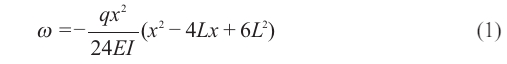
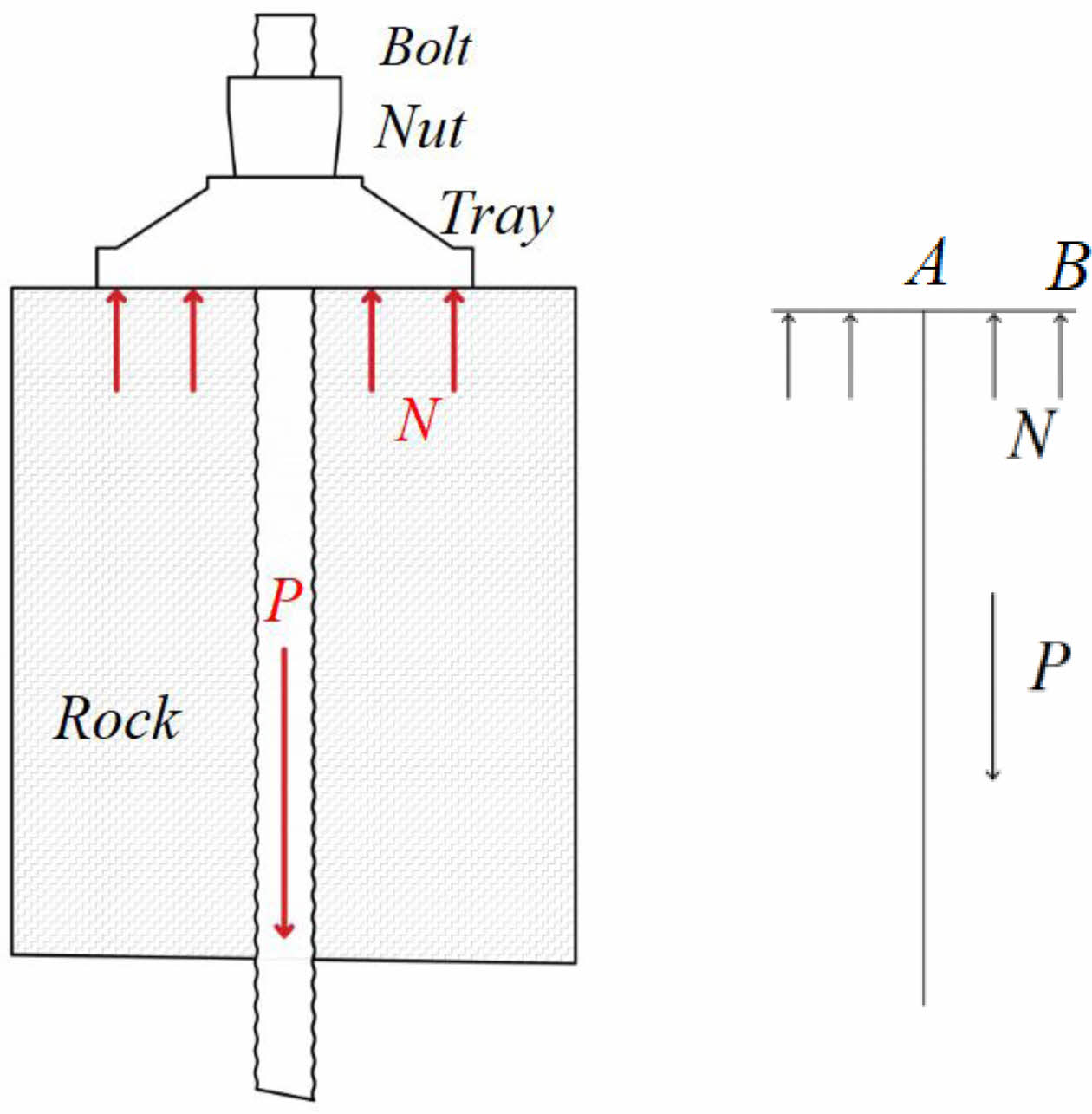
The model of a cantilever beam under uniform load in the mechanics of materials is used to analyse the stresses and strains in the tray after the load from the surrounding rock [18]. The tray emerges as a homogeneous rotating body, the section view of the tray on one side is taken for the force analysis (A is the centre while B is the edge). The force at the edge of the tray has been simplified as shown in Fig. 3. Fig. 4
The equation of the deflection curve:
Shear stress equation:

ω is the deflection of the tray edge, m; q is the loading of the bottom, N/m; L is the radius, m; F is the shear stress, N; E is the modulus of elasticity of the tray material, GPa; I is the moment of inertia, m4.
From Eq. (1), as the value of x increases, which means away from the anchor fixing position at the centre, the amount of deformation at the edge will rise. From Eq. (2), as the value of x decreases which means near the centre,the shear stress becomes larger, while the boundary stress is minimal. Once the deformation of the edge exceeds its maximum, it will rupture. Moreover, the deformation continues to increase and the crack extends towards the centre, thus causing the whole break of the tray.
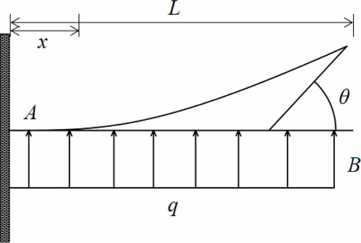
Squeezing by the surrounding rock, the tray is closely locked to the nut. Meanwhile, it is subjected to the expansion forces of the conical face of the nut [17]. Fig. 3 shows the theoretical analysis of the forces in the tapered hole of the tray. Besides, the coordinate system is established with the axial direction of the anchor designated as the Z-axis and the direction perpendicular to the Z-axis as the X-axis. We take a point on the inner surface to make force analysis. The inner tapered surface of the tray is subjected to two forces, one is the frictional force f generated when the relative motion occurs between the nut and the tray, presenting angle θ to the Z axis. Another force is the positive pressure exerted by the nut perpendicular to the inner surface of the tray, presenting angle θ to the X axis. The two forces are decomposed along the X and Z axes, working out forces in the X and Z axes respectively, as shown in Eq. (3) and Eq. (4).
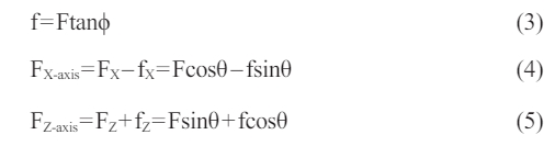
ϕ is the coefficient of friction between the nut and the inner wall, tan ϕ = 0.2, and θ is the angle of inclination of the inner surface.
When axial force is applied to the bolt, the inner surface of the tray exist forces along the positive Z-axis and X-axis. Therefore, the tray shows two kinds of deformation in the inner surface, one of which is under the action of FZ-axis, resulting in axial damage of the tray. The other deformation is under the action of FX-axis, resulting in circumferential expansion and deformation. On the inner surface of the taper hole, the area with the small diameter is thick. Whereas the area with the large diameter is thin, therefore, it represents the weak part of the structure. As such, the tray tends to expand and rupture after receiving the X-directional force. Instead, with the Z-directional force, the area with small diameter is the weak part at the bottom and can be easily extruded by the nut to break after receiving the force.
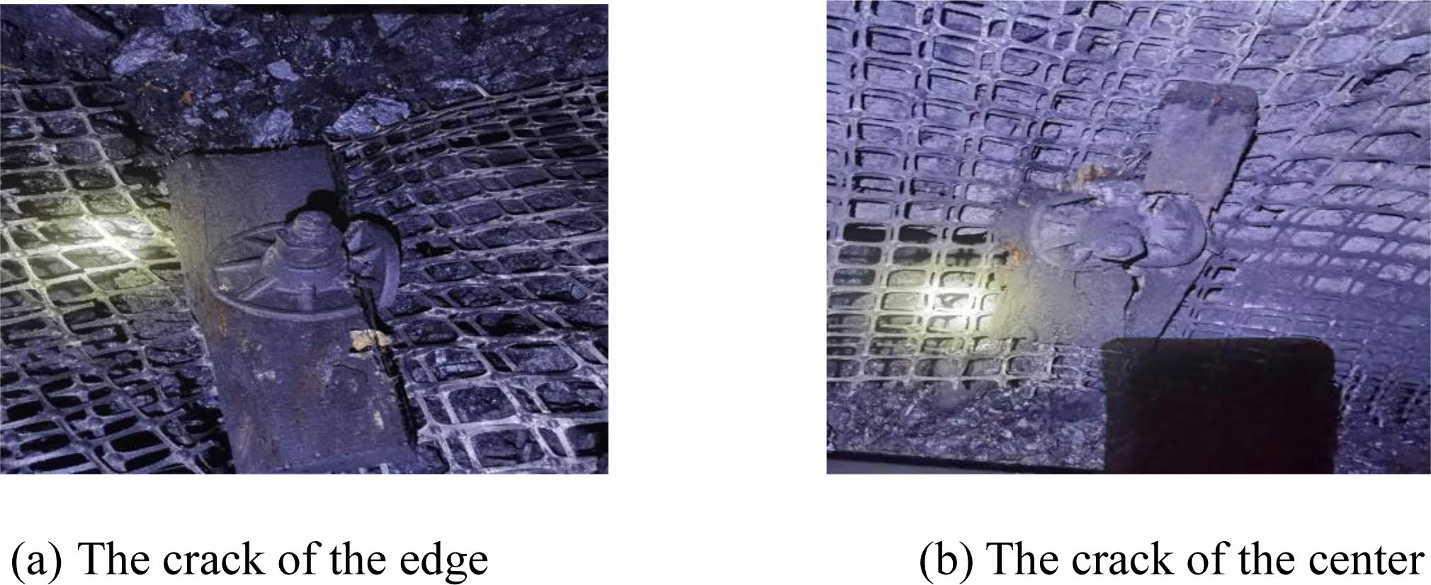
In the underground coal mine support sites and during the experiment, the common damage of the trays are rupture of the edge, crack of the top ring and crash of the small circular hole at the bottom. The areas of tray failure are the same as the weak parts in the force analysis, as shown in Fig. 5.
Force finite element analysis and structural optimization of composite trays
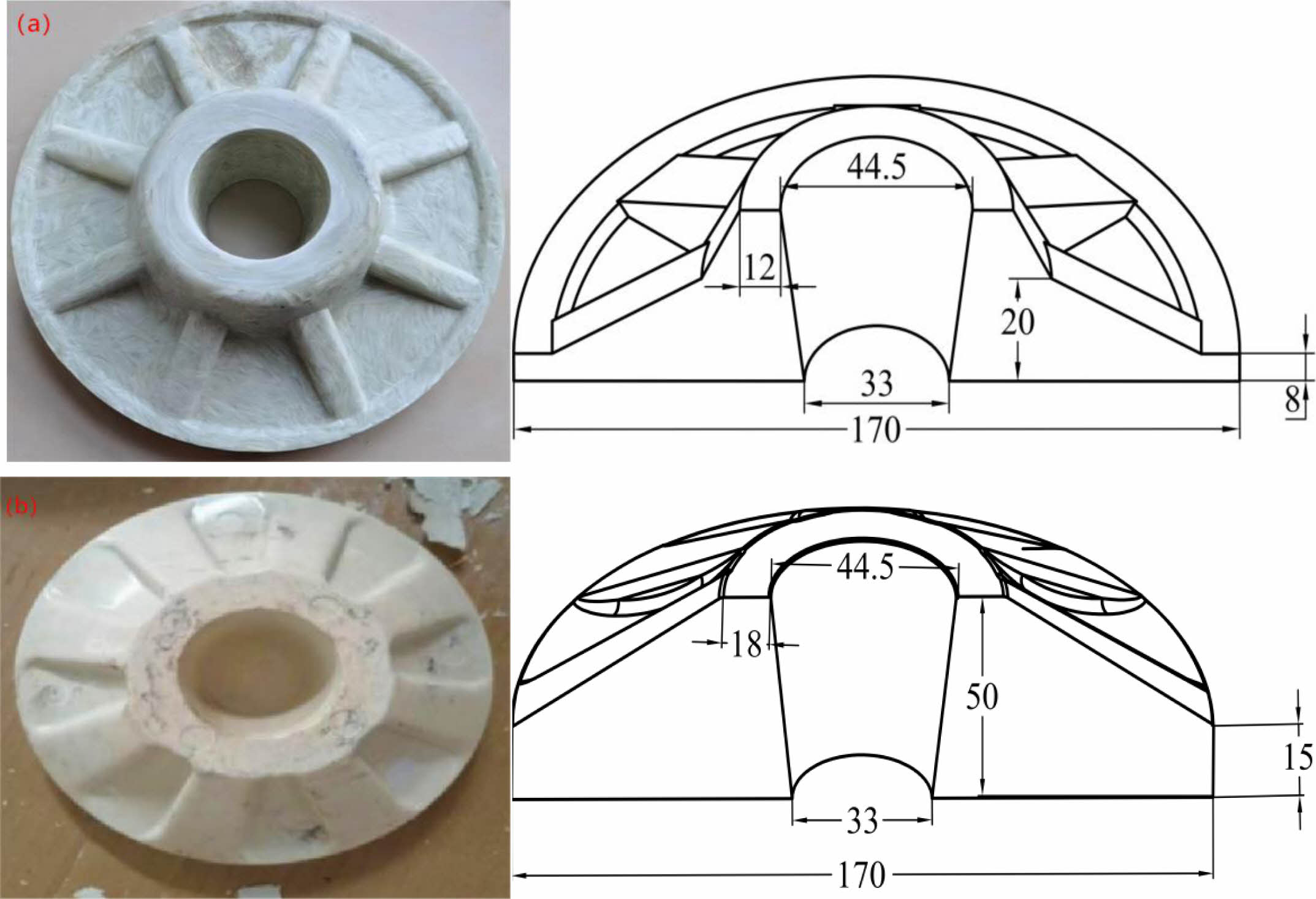
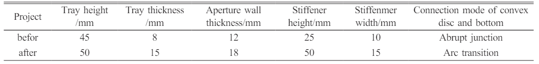
The structural design of the composite trays involves in the chosen material, the bearing capacity, the process and the size of the bolts,etc. From the damage and force analysis of the tray in the field application, it is clear that the stress distribution is more concentrated at the bottom edge, the top screw hole, the bottom screw hole and the connection of the large and small discs inside the tray. Fig. 6(a) suggests the the composite tray in general use. The thickness of the disc at the bottom and that of the tapered hole, the shape of the stiffener and the abrupt connection between the raised disc and the bottom of the tray all have negative impact on the bearing of the tray. Therefore, the dimensions and key structural parameters have been optimized for these locations. Besides, the shape of the optimized tray is shown in Fig. 6(b). The changes in the tray structure parameters before and after optimization are shown in Table 2.
According to the diagram, the height of the stiffener is the same as that of the tray. The stiffener is connected to the top round edge of the tray with its root linked to the bottom fan-arc surface. The radius of the transition arc is 8 mm. The width of the stiffener is 15 mm. The radius of the transition arc beside the rib is 8mm. After optimization, the top convex side and the bottom present a hook face, the radius of which is 80 mm. The thickness of the raised circular hole is 18 mm and the thickness of the edge is 15 mm. The cross-sectional shape of the stiffener and the transitional structure effectively strengthen the taper hole and the circular surface of the bottom.
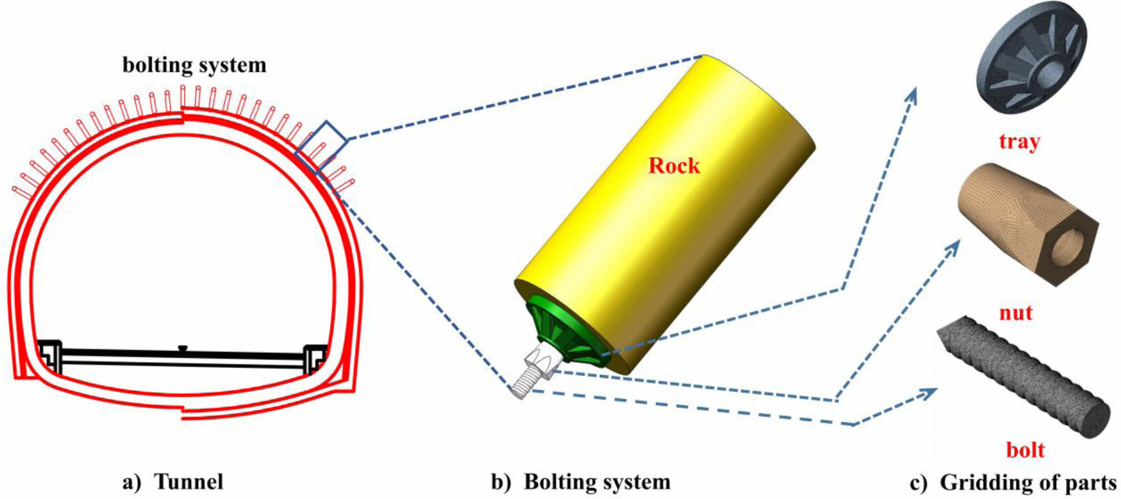
As shown in Fig. 7, the finite element simulations have been adopted to verify the bearing effect of the optimized tray and to analyze the stress-strain distribution of the tray under 200 KN axial load before and after structural optimization. Based on the FEM of ANSYS program, integral modeling of bolt tray and nut has been built to simulate the stress-strain cloud chart of the tray under axial load. The 3D model of the bolting system is shown in Fig. 6. The bolt crosses the tray centre and is secured to the rock by the preload of the nut. The surrounding rock adopts elastic constitutive model. Moreover, hexadecimal dominant method is adopted in mesh generation, the module being divided into hexahedra with the size of 5 mm. The mesh size of the tray, nut and bolt is 1 mm. While the mesh size of the inner surface of tray, nut and bolt is changed to 0.5 mm. The accuracy of the results is ensured by calculations of different mesh sizes.
In the model, the tray is restrained by the surrounding rock and the nut, posing axial force to the bolt. The stress and strain distribution has been analyzed. Meanwhile, the nut is subjected to axial tension of the bolt, thus touching the tapered surface and squeezing the tray. In this connection, the stress and strain distribution of the conical surface also has been analyzed.
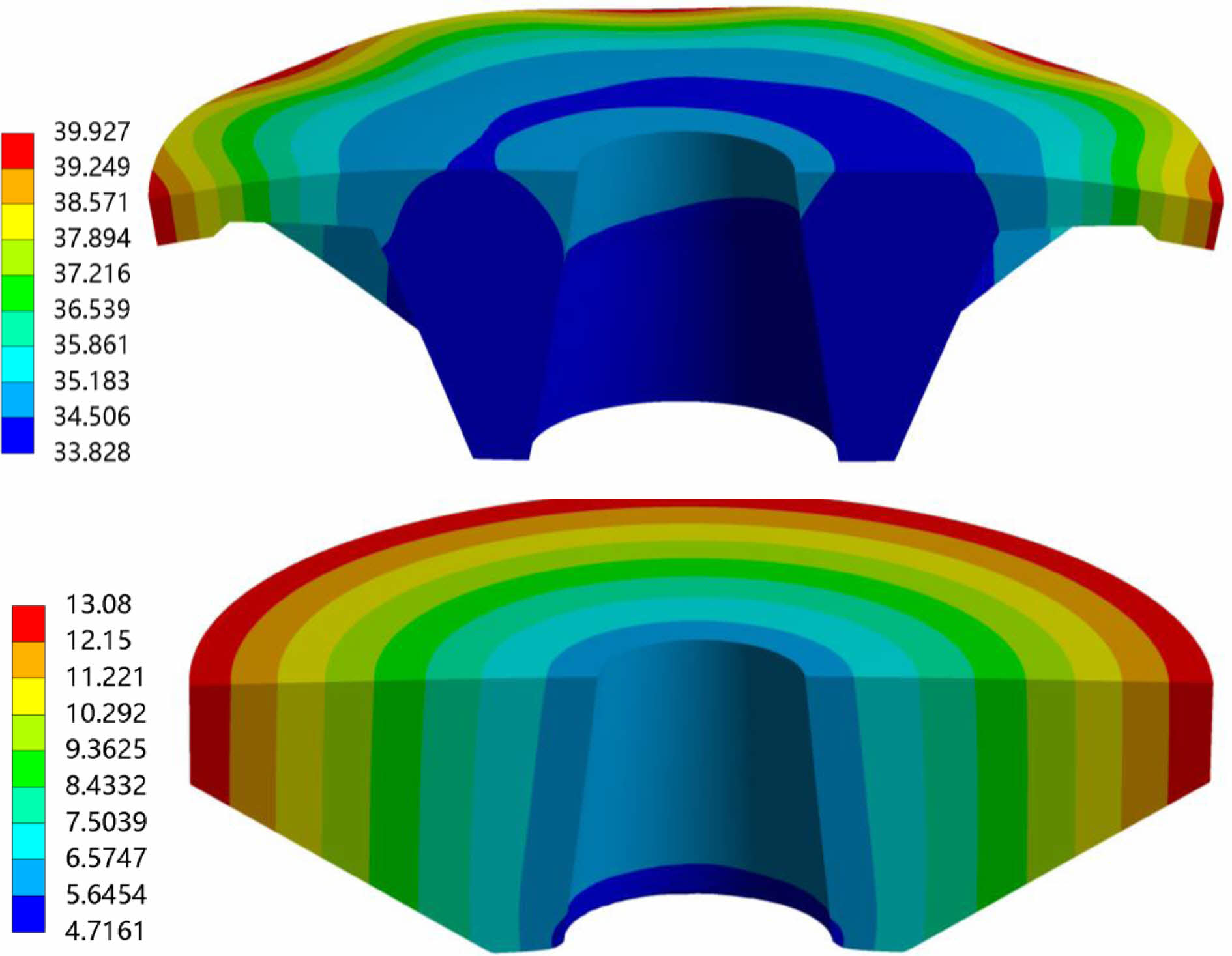
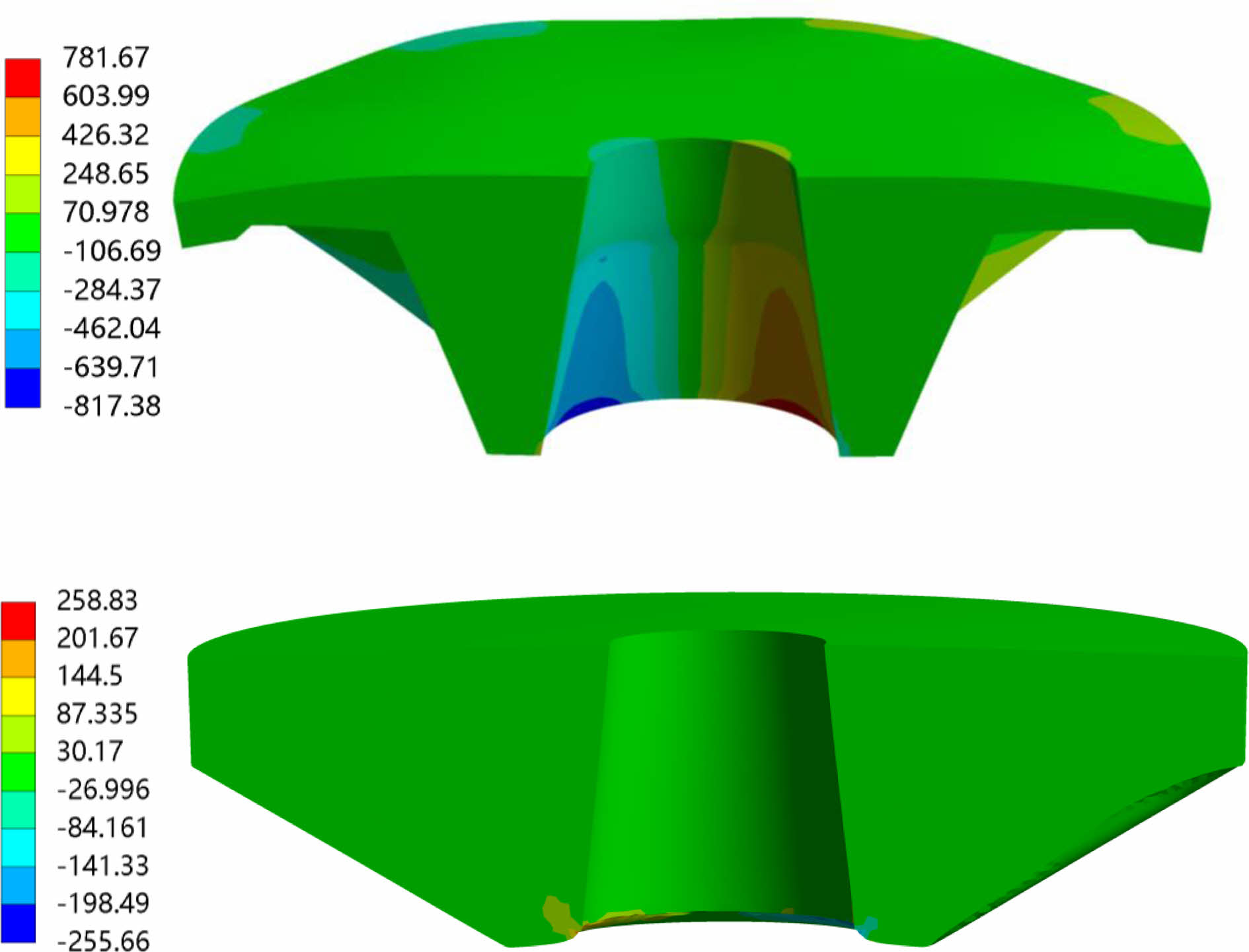
Fig. 8 manifests the results of the numerical analysis of the deformation of the tray before and after optimization with the same load. In order to show the deformation of the inner surface of the taper hole, the tray is split transversely. Based on the diagram, the bottom edge is subjected to the extrusion of the surrounding rock. It belongs to the central zone of transformation, manifesting the force of simply supported beam. Before optimization, the tray edge is thin and the stiffener is low with a local strain concentration area coming into being. After optimization, the strain distribution at the edge is even with no local stress concentration area. The deformation of the bottom edge turns from 39.9 to 13.08 after optimization, reducing approximately 67%. What’s more, the top edge is the stress concentration area with the largest deformation, which extends along the conical side towards the small hole at the bottom. The overall deformation of the taper hole before optimization is obvious, which is mainly reflected in the extension along the axial and radial directions compared with that of the tray after optimization. The maximum deformation at the large end edge of the tapered hole turns from 33.8 mm to 4.7 mm after optimization, reducing approximately 86%.
Fig. 9 shows the results of the numerical analysis of the shear stress distribution in the tray before and after optimization with the same load. From the figure, the maximum shear stress of the tray with different structures is concentrated at the top of the conical surface. The maximum shear stress is 781.67 Mpa. It extends from the top edge along the conical surface. After optimization the maximum shear stress is 258.83 Mpa, which is only distributed locally at the top edge of the tray, reducing about 66.8%. At this point, there exist no shear stress concentration area at the bottom edge.
Forming and mechanical properties of composite SMC trays
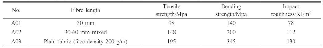
Considering the results of the above analysis, SMC sheets with different fibre lengths are made into trays and tested for strength. The different sheets are moulded into 2 mm sheets and tested for tensile strength, bending strength and impact toughness, the results of which are shown in Table 3.
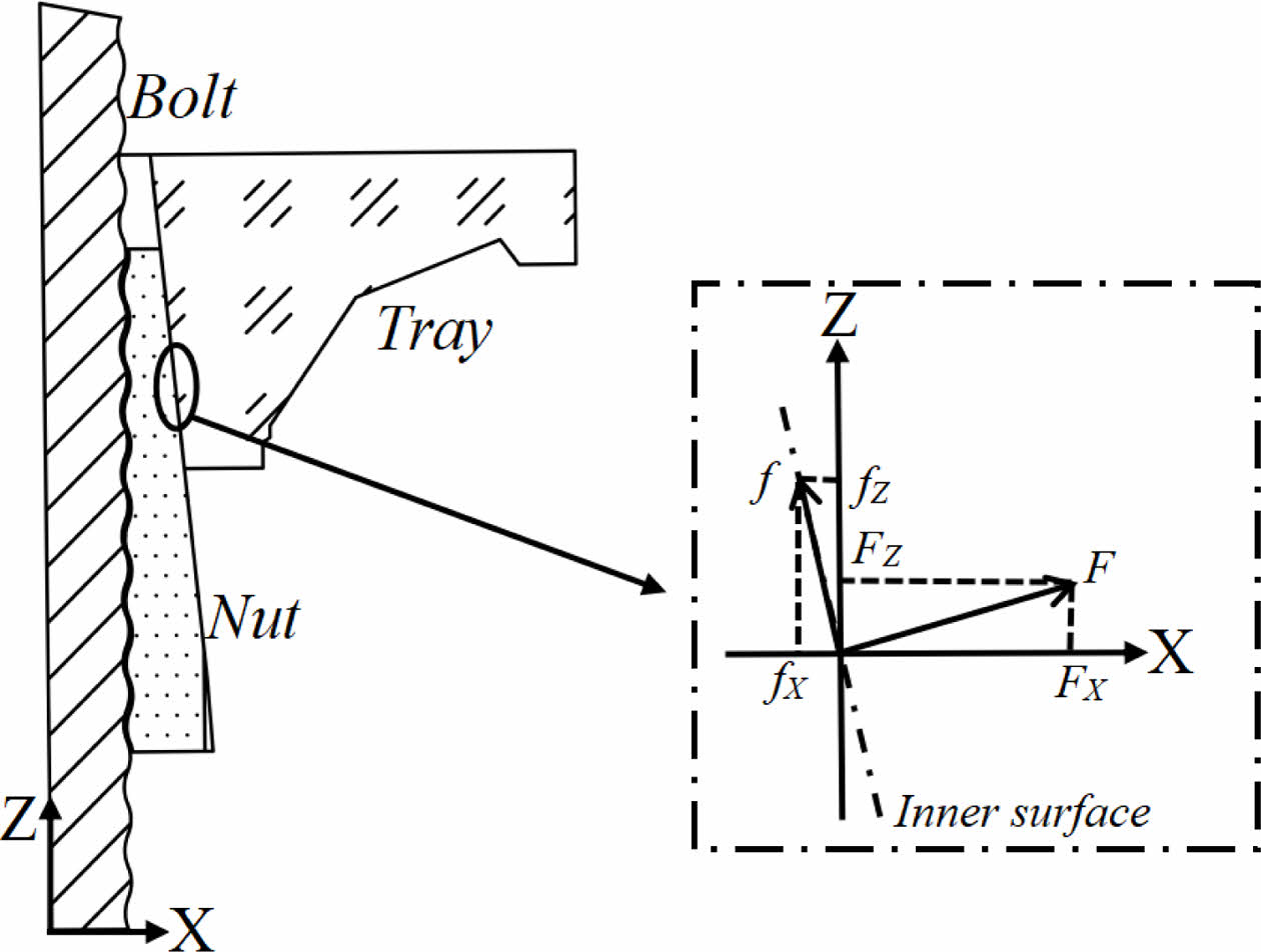
It can be seen from the results that the strength of the composite rises with the increase of the fibres. The sheet reinforced with continuous fibre fabric shows the best mechanical properties. The equation for the mechanical properties of short-cut fibre-reinforced composites is as follow [19].
σc-composite stress, (σf)max-maximum fibre stress, Cf-fibre volume content, l-fibre length, lt-critical fibre length, σm-matrix stress, Cm-matrix volume content.
From the above equation, when the fibre length is larger than the critical length, the composite strength gradually increases close to that of the hybrid composite as the fibre length rises. When the fibre length is short, the stress concentration at the end of the fibre is more obvious compared with long fibres, which may cause matrix cracking and fibre pull-out when subjected to external forces. As the fibre length increases, the stress concentration at the end of the fibre is relieved while augmenting the axial stress. Such being the case, the increase in fibre length makes great difference for the improvement of its tensile modulus.
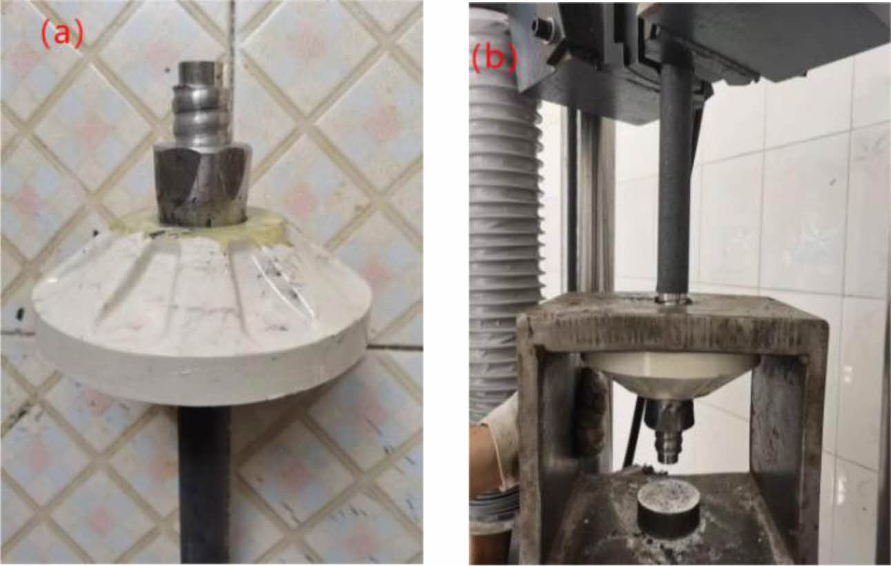
Three different SMC sheets, A01, A02 and A03, have been used to make the trays. For experimental comparison, we utilized A03 sheets to produce common trays. Meanwhile, the tray with tapered holes reinforced with an insert structure was also processed with A03. The composite bolting system consists of three parts: the bolt, the tray and the nut. The carrying capacity is influenced by the strength of each part as well as the matching of the three parts. In order to exclude the impact of the composite bolt and nut on the strength of the tray, the ultimate strength of the tray was tested by using a metal bolt and a metal nut. They have a high dimensional and matching accuracy, as shown in Fig. 10(a). The bolting system with the composite tray was mounted on a homemade test fixture and the load was applied axially along the anchor stem until the tray broke, as shown in Fig. 10(b).
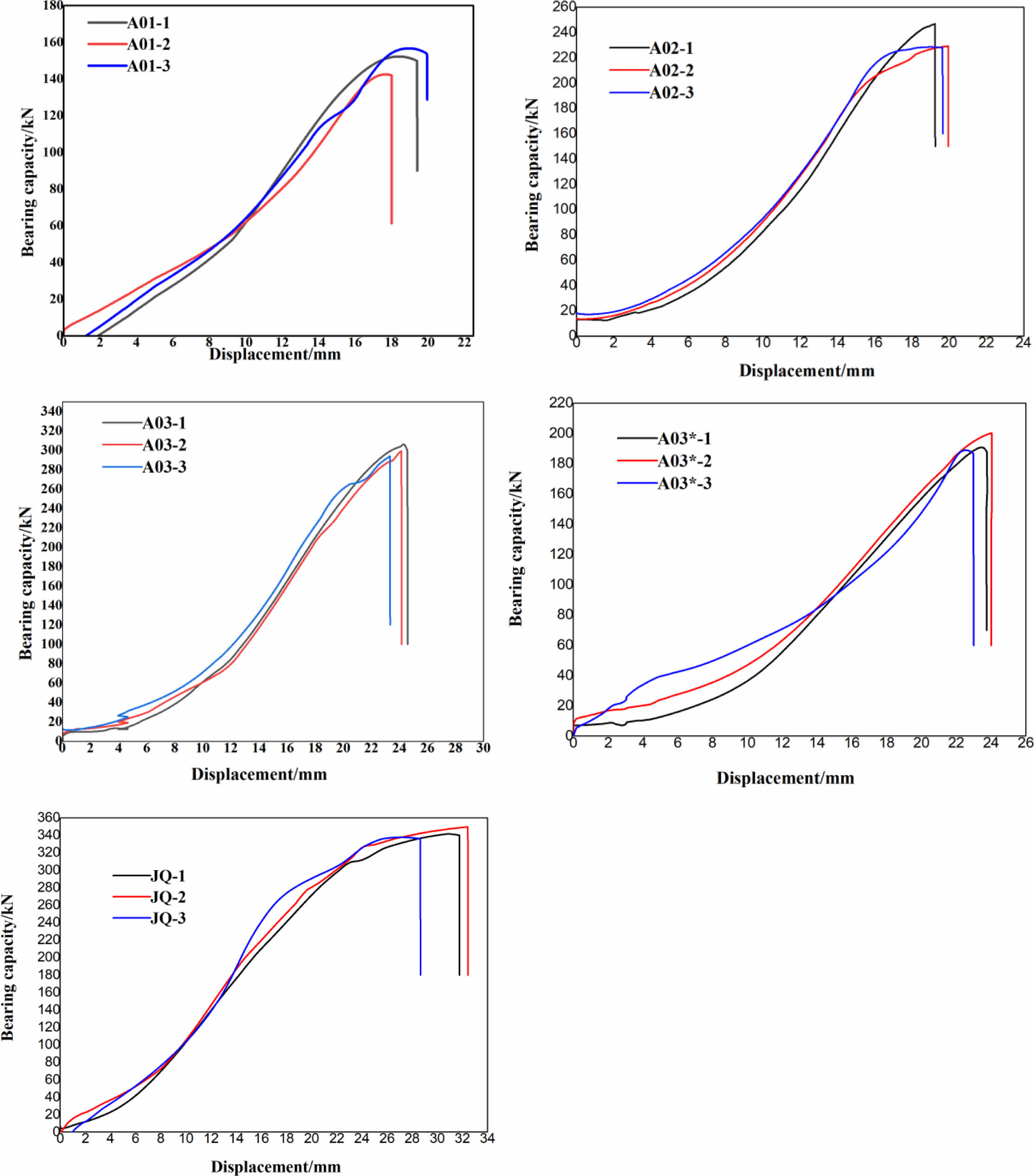
Tray bearing capacity and displacement relationship curve of the tray are shown in Fig. 11. At the beginning of loading, there is a gap between the nut and the tray as well as between the tray and the obstructed surface. After being pulled, each part becomes closely matched. As the increase in displacement, the bearing capacity gain little rise. When the tray and the nut completely integrate with each other, as the displacement increases, the tray bearing capacity rises sharply. While the displacement increases to about 20 mm, the conical surfaces of the nut and the tray begin to squeeze the tray. At this point, bearing capacity reaches the maximum and the nut displacement space is limited. The tray and the nut are slowly deformed under the mutual force with the bearing capacity continuing to increase slowly. Once the limit bearing capacity of the tray is exceeded, the tray will rupture.
After optimization, the strength of the tray have been increased as the length of reinforced fibre increasing, among which the bearing capacity of tray with continuous fibre-reinforced sheets is up to 280 KN. While the bearing capacity of ordinary trays pressed with the same material is 200 KN. Besides, trays with taper holes reinforced with continuous fibre prepreg inserts show the bearing capacity of 340 KN, which is the same as that of a 25 mm diameter bolt made from BHRR500 rebar.
Except for the trays with tapered hole partially reinforced , other trays are damaged in the large end of the tapered hole, with cracks expanding along the radius up to the bottom edge, as shown in Fig. 12. For fibre lengths of 30 mm SMC, they have concentrated fibre and matrix end effects. Thus, when the bearing capacity exceeds the material strength, the tray collapses from the tapered hole with larger cracks, mainly in the form of matrix cracking and fibre pull-out. For trays reinforced by continuous fibre sheet, fibres bear the most weight. As such,the tray crack is much smaller, which mainly shows matrix cracking and fibre fracture, extending from the taper hole along the radial and axial directions. For trays with reinforced insert, the insert increases the bearing capacity of the taper hole and inhibits the damage of cracks from the taper hole. When the load exceeds the ultimate strength of the material, the bottom ruptures as a whole with the cracks extending to the top large end of the tray, ultimately causing the whole crack.
|
Fig. 2 Simplified diagram of the overall forces in the bolting system. |
|
Fig. 3 Force model of the edge simply supported beam |
|
Fig. 4 Force analysis of the tapered hole in the tray. |
|
Fig. 5 Diagram of tray damage during support. |
|
Fig. 6 Optimized design of the tray structure (a) before (b) after. |
|
Fig. 7 Finite element model of the anchor support system |
|
Fig. 8 Distribution of tray deformation before and after structural optimization |
|
Fig. 9 Shear stress distribution before and after structural optimization of the tray. |
|
Fig. 10 bearing test (a) composite tray with metal bolt and nut (b) test condition. |
|
Fig. 11 Bearings capacity and displacement curves for composite trays (A03* is a common structural tray pressed with fabric reinforced SMC sheet; JQ is a tray pressed with fabric reinforced SMC sheet after structural optimization). |
|
Fig. 12 Composite tray after bearing test: (a) Broken top of tray and (b) Broken bottom of tray. |
Based on theoretical force analysis and finite element analysis, the material and structure of the composite anchor trays have been optimized and the high-strength SMC sheets can be used to process the high-strength composite trays. The conclusions are as follow:
The main stress concentration areas and deformation areas of the tray were observed through material mechanics and finite element simulation analysis. According to the results, the tray ruptures or breaks mainly due to the expansion and deformation of the taper hole by the nut, which causes the centre to rupture and lead to the crack of the whole tray. Numerical simulation results are consistent with the conclusion of theoretical stress analysis.
Based on the findings of the force analysis, the structural parameters of the tray have been optimized. After optimization, the maximum deformation at the top edge of the cone turns from 33.8 to 4.7, reducing approximately 86%. The shear stress at the top edge of the tray turns from 781.67 to 258.83, reducing about 66.8%.
The bearing capacity of the tray is up to 250 kN with continuous fibre-reinforced SMC sheets. Whereas with partial reinforcement of the tapered holes, the bearing capacity is up to 304 kN.
- 1. Y. Chen, Q. Meng, G. Xu, H. Wu, and G. Zhang, Int. J. Min. Sci. Technol. 26[5] (2016) 777-785.
-

- 2. R. Das, and T.N. Singh, Nndergr. Space. 6[4] (2020) 409-420.
-
- 3. J. Hadjigeorgiou, J.F. Dorion, and E. Ghali, J. S. Afr. Inst. Min. Metall. 108[6] (2008) 359-365.
- 4. S. Divi, D. Chandra, and J. Daemen, Tunn. Undergr. Space Technol. 26[1] (2011) 124-129.
-
- 5. X. Liu, Y. Han, C. Yu, F. Xiong, X. Zhou, and Z. Deng, Comput. Geotech. 125 (2020) 103661.
-
- 6. Z. Liu, C. Zhou, Y. Lu, X. Yang, H. Liang, and L. Zhang, Sens. 18[9] (2018) 2763.
-
- 7. M. He, Y. Peng, S. Zhao, H. Shi, N. Wang, and W. Gong, Int. J. Min. Sci. Technol. 25[4] (2015) 531-535.
-
- 8. H. Liu, K. Deng, S. Lei, and Z. Bian, Int. J. Min. Sci. Technol. 25[4] (2015) 553-558.
-
- 9. H. Li, Z. Du, S. Geng, W. Han, and Y. Wu, Mater. 15 (2022) 2346.
-
- 10. X. Feng, N. Zhang, F. Xue, and Z. Xie, Int. J. Rock Mech. Min. Sci. 123 (2019) 104097.
-
- 11. Z. Xiang, N. Zhang, D. Qian, Z. Xie, C. Zhang, F. Guo, and S. Wang, Hindawi Ltd. 2021 (2021) 1-16.
-
- 12. B. Wang, Z. Wang, X. Guo, J. Dong, and Z. Wang, Rock. Mech. Rock. Eng. 132 (2024) 1-18.
-
- 13. Z. Chong, T. Yue, Q. Yao, X. Li, C. Zhang, Z. Xia, and H. Li, Eng. Fail. Anal. 122 (2021) 105259.
-
- 14. M. Marenče, and G. Swoboda, Rock. Mech. Rock. Eng. 28[3] (1995) 145-165.
-
- 15. Senthilkumar K.M, Kathiravan N, Girisha L and Sivaperumal M, J. Ceram. Process. Res. 23[4] (2022) 541-545.
-
- 16. Senthil Kuma KM, T. Ramanathan, S. Murugesan, and V. Thangamuthu, J. Ceram. Process. Res. 22[6] (2021) 731-738.
-
- 17. D. Zhao, S. Wen, L. Wang, and B. Zhang, Constr. Build. Mater. 310[6] (2021) 125081.
- 18. J. Li, Z. Du, S. Geng, and W. Han, Mater. 15 (2022) 2346.
-
- 19. P.G. Malchev, and C.T. David, Polym. 46 (2005) 3895-3905.
-
 This Article
-
2024; 25(2): 202-211
Published on Apr 30, 2024
- 10.36410/jcpr.2024.25.2.202
- Received on Sep 14, 2023
- Revised on Oct 23, 2023
- Accepted on Nov 8, 2023
Services
Shared
Correspondence to
- Xu-feng Zhang
-
School of Materials Science and Engineering, Beijing Institute of Technology, Beijing 100081, China
Tel : +8617710239296 Fax: 010-68945462 - E-mail: 010xufeng@sina.com
Clean-Energy Research Institute(CRI), Hanyang University, 222, Wangsimni-ro, Seongdong-gu, Seoul, 04763, Korea
E-mail: jcpr@hanyang.ac.kr