- Numerical and experimental validation for effective cross-sections in pulse detonation engine design
S. Srikrishnana,*, T. Shaafib and P.K. Dashc
aDepartment of Mechanical Engineering, Saveetha School of Engineering, Saveetha Institute of Medical and Technical Sciences, Chennai 602105, India
bDepartment of Agricultural Engineering, Saveetha School of Engineering, Saveetha Institute of Medical and Technical Sciences, Chennai 602105, India
cDepartment of Aerospace Engineering, Sandip University, Nasik, Maharashtra 422213, IndiaThis article is an open access article distributed under the terms of the Creative Commons Attribution Non-Commercial License (http://creativecommons.org/licenses/by-nc/4.0) which permits unrestricted non-commercial use, distribution, and reproduction in any medium, provided the original work is properly cited.
Industrial revolution and economic growth in any country is aided and abetted by effective defense research and development hand in hand with medical supremacy across the globe. Advent avionics system and advanced defense technology have sprung up from various nations further driving the need for hypersonic speed propulsion systems in transport or military applications. Pulse detonation systems may be an effective cure for such insolvency and may be used as an advanced highspeed propulsion system for various applications. The research work discusses the effect of cross-sections like cylinder, square and rectangle in achieving controlled detonation with supersonic velocity at exit and effective pressure for further expansion. The analysis resulted that the cylindrical cross-section with an orifice type blockage at three locations evenly spread throughout the length of the tube with 60 percent blockage ratio to be the most effective with maximum exit velocity of 2995.6 m/s and effective pressure of 10.5 bar for an injection pressure of 100 bar and velocity 0.15 m/s. An experimental model using cold flow was conducted to ratify the results from the numerical simulation and found to be similar with a differentiation of 14% due to the variation of the working fluid
Keywords: Cross-section, Deflagration to detonation transition, Kerosene, Optimization, Pulse detonation engine
PDE : Pulse Detonation Engines
CFD : Computational Fluid Dynamics
ZND : Zel’dovich-von Neumann-Döring Model
CD : Convergent-Divergent
DDT : Deflagration to Detonation Transition
H2 : Hydrogen
NOx : Nitrogen Oxides
Research motivation
The motivation behind the research is to gain a better understanding of single-pulse and multi-pulse activities in various types of Pulse Detonation Engines (PDEs) with and without nozzles and ejectors. The goal is to improve the performance and efficiency of PDEs.
Literature review
Different mathematical and scientific examinations were made to achieve a superior comprehension of single-pulse and multi-pulse activities of different single cylinder or
multi-tube PDEs in mix with and without nozzles and ejectors. To gauge the exhibition of PDEs, a basic model was proposed by Endo and Fujiwara [1]. The model comprises of a straight cylinder, shut down toward one side and open on the opposite end, having an explosion locale close to the shut end and does exclude a spout at the power source. The one cycle beat comprises of three stages: burning, exhaust, and filling stages. The reenactments completed on this model showed that through worked on hypothetical examination, valuable formulae for drive thickness per unit cycle activity and time-arrived at the midpoint of push thickness could be determined. Scientific investigations embraced by Yungster
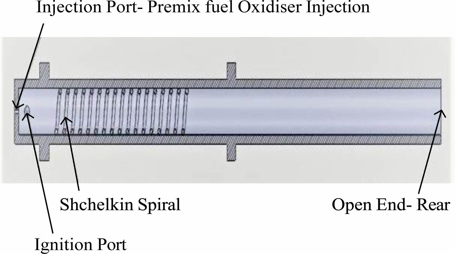
[2] to comprehend the impacts of adding spout at exhaust of explosion tube. A mathematical model was planned and computational liquid elements was utilized to affirm results. Single pulse mockups for a 1.0 m long cylinder with or without spout loaded up with hydrogen-air blend. Multicycle investigation results showed that the ignition residue should be cleansed from spout before beginning of next cycle, for spout to work adequately. Fig. 1 shows the sample of experimental setup of pulse detonation engine with Shchelkin spiral.
One of fundamental difficulties of creating PDEs for all intents and purposes, is the prerequisite for rehashed commencement of explosions inside explosion chamber. The prerequisite to catch the time-precise movement of explosion wave is challenge in computational displaying. Shihari, Mallesh et al. [3] examined the one-venture in gen- eral response model to lessen this computational burden. Both 1-D and 2-D axisymmetric tubes were considered for reproductions. Their investigations showed that one-venture model is adequate to anticipate the stream properties. They additionally examined the impact of various framework sizes on the event of von Neumann spike, CJ pressure factor and explosion speed.
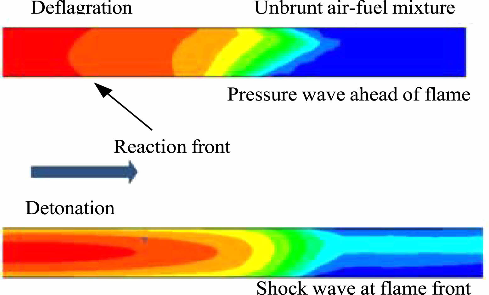
Ongoing examinations are being completed on PDE- crossover gas turbine. CFD examination did by General Electric Global Research Center, NY; considered the PDE-turbine connections with PDE procedure on H2-air found upstream of one column of fixed, 2D turbine edges [8, 9]. The outcome showed that the framework arrived at a semi consistent state quickly for multi-cycle reproductions than a solitary beat, along these lines featuring the constraints of single cycle estimations [10]. From the literature on computational investigations, it is seen that none of the models proposed have endeavored to address the temperamental stream in a cylinder having merging or separating tube math. For the most part, execution assessments of PDEs is finished utilizing a romanticized straight explosion tube without bays or some other extra mechanical assembly [11, 12]. The investigation of ZND conditions are then concentrated as the wave spreads along the length of cylinder till the open end. It isn’t totally conceivable to play out an immediate examination between the reenacted results and trial information as the impacts of variables, for example, initiators utilized and the limit conditions applied contrast. Fig. 2 shows the difference between deflagration and detonation in terms of computational simulation and development of flame front [13, 14].
Authors in [4] directed CFD recreations to examine stream elements and framework execution of air-breathing PDEs utilizing H2-air one stage response model. The reproduction model comprised of supersonic delta, an air complex, a rotational valve, a solitary or a multi-tube combustor, and a joined dissimilar spout at predefined flight conditions [5, 6]. It was seen that keeping cleanse time steady with longer topping off cycles, expanded the particular push and C-D nozzle builds the drive proficiency as the throat region assumes a more significant part than tube length [7]. It was additionally noticed that multi-tube PDEs work on functional relentlessness of the framework contrasted with single-tube calculation. This calculation helps diminish the defective nozzle development loss, nonetheless, it prompts more confounded shock waves and interior stream loss, accordingly diminishing by the large propulsive execution.
Trial investigations in pulse detonation motors are supposed to have cautious perceptions on detonation ignition reproductions; nevertheless, a few analysts noticed that mathematical reenactments are also required to image the explosion burning miracles in PDE combustor. Soni et al. [15] used a cost-effective CFD model to simulate a PDE combustor with and without deterrents and a hydrogen-air mixture. It is discovered that obstacles are beneficial to PDE combustor planning and development. Amin et al. [16] investigated the effects of various spout computations and operating
circumstances on the appearance of a heartbeat explosion motor. The CFD results demonstrate that a divergent nozzle is more compelling than a CD spout at low encompassing pressing factor.
Tangirala et al. [17] recreated the presentation of the PDE in subsonic and supersonic flying circumstances. Their initial parametric tests were performed on a 2D CFD model. The results indicated that the leave spout improves push age, maintains working pressing factor, and regulates working recurrence. Using a one-stage 3D mathematical compound response model, Shao et al. [18] investigated the effect of several types of nozzles on a continuous detonation motor. The four types of nozzles discussed are the constant area nozzle, Laval nozzle, diverging nozzle, and CD nozzle. The outcomes demonstrated that Laval nozzle has incredible breadth to further develop the impetus execution of this framework.
Ma et al. [19] investigated the influence of single-tube and multitube PDEs on the spout stream field on propulsive execution. In this study, push variety cross over occurred as a result of a decrease in pivotal stream movements and provides a more wide activity range in terms of valve timing. They showed that joined spout assists with keeping the first chamber pressure steady and therefore further develops the motor net exhibition. Winten-berger and Shepherd considered the stream way in a solitary cylinder beat explosion motor. They fostered this logical model for recreating the stream and for assessing the presentation and they contrasted it and optimal ramjet motor. They saw that motor push relies upon explosion tube motivation, force, and pressing factor terms. The outcome likewise demonstrated that the absolute pressing factor misfortunes were caused because of precariousness of the stream.
Kailasanath and Patnaik [20] introduced a survey of computational examinations on beat explosion motor. The objective of this research was to evaluate the time subordinate mathematical recreations of PDE. They discovered that the underlying circumstances in reproductions had a significant influence on overall execution. Ma et al. investigated the inner flow components of a heartbeat explosion motor that used ethylene as a burnable fuel. The stream assessment and explosion wave aspects were rebuilt. A study of activity time was also conducted for the motor plan advancement affectability. Frolov and Aksenov showed the deflagration to explosion progress in a cylinder with constant progression of a pre-disintegrated TS−1 fly lamp oil air combination at barometrical pressing factor [21]. In this examination fuel burning was seen in explosion ignition mode.
Johansen and Ciccarelli led enormous whirlpool recreation of beginning fire speed increase in an impeded channel [22]. Using large swirl reproduction, the effect of impediment blockage percentage on the improvement of unburned gas
stream field in front of fire front in a hindrance channel was investigated. The computational reenactments indicate that choppiness production increases as the fraction of impediment blockage increases. This strategy should have been attempted for reconstruction of detonation waves. Frolov et al. recreated the explosion wave distributed in a planar channel, round and hollow cylinder, and two U-shaped twists constraining ebb and flow [23]. Otsuka et al. considered the impact of U-twist on explosion wave engendering with computational liquid elements investigation [24]. Their findings reveal that explosion waves disappear near the U-twist ebb and flow gulf and reappear after passing through it. They also discovered that a U-twist with a small channel width and arch range can cause rapid DDT. The beginning vortex was produced and execution was influenced by the math of ejectors. On the opposite side ejector length is less significant and large execution contrasted with the ejector measurement.
The unstable push increase was concentrated by Zheng et al. The perfect starting vortex was created by the optimal ejector breadth, and investigation also revealed a modest influence of ejector length [25]. The push expansion was discovered to increase with the length of the ejector. The ejector execution was clearly susceptible to the working fill division. Zhang et al. explored the ejectors execution on push increase in beat explosion motor [26]. As a result of the mathematical analysis, they were able to determine the basic spread cycles of PDE explosion waves, as well as the secondary explosion waves generated. On the other hand, there was some thought given to the intricacies of stream field of the explosion wave generated within an explosive barrel and its infusion into the blast [27], [28]. The turning wave ejector idea has exceptionally critical potential for push expansion comparative with an essential heartbeat explosion motor [29, 30].
Yi et al. contemplated the impact of ejector in beat explosion rocket impetus framework [31]. They noticed different elements including explosion shock association, explosion diffraction, and vortex arrangement in spread of hydrogen-oxygen blend explosion. Stoddard et al. considered the CFD investigation on explosion wave proliferation and coming about fumes gas elements [32]. The reenactments are taken towards upgrading a static push on beat explosion motor. Tan et al. considered the explosion wave in movie form elements and inferred that warm insurance is vital and vital for the plan of a heartbeat explosion combustor [33]. He and Karagozian considered the transient, receptive compressible stream wonders in beat explosion wave motor computationally [34]. The motor presentation boundary and also motor commotion were assessed inside and outer to explosion tube. Yungster et al. concentrated mathematically the development of NOx in hydrogen-powered heartbeat explosion motor. Their outcomes demonstrated that NOx development in beat explosion motor is exceptionally high for stoichiometric combination. Ma et al. concentrated mathematically inner stream elements in a valveless air-breathing
heartbeat explosion motor working on ethylene fuel [35]. Experimental investigation indicates that alloy-based coating given on the surface of the combustor [39] may increase the efficiency of the reaction. Further the thermal barrier coatings are necessary from salvaging the surface from aerodynamic erosion [40].
Necessity of reseaech
The challenges identified in the literature review highlight the need for further research. These challenges include the requirement for repeated initiation of explosions, capturing the time-accurate motion of explosion waves in computational modeling, unstable flow in converging or diverging tubes, and the discrepancies between simulated results and experimental data.
Novelty and main contributions
The paper’s novelty and main contributions include the development of a one-step reaction model to reduce computational burden, CFD simulations to analyze flow dynamics and system performance of air-breathing PDEs, investigation of different cross-sections like circular. square and rectangular. Also experimentally perform the cold flow analysis to give a comparative study of numerical and experimental results to ratify the CFD simulation results.
Organization and structure
The paper follows a structured approach, discussing different aspects of PDE research in separate sections. It begins with introduction, followed by methodology where numerical and experimental methods used to perform the research have been consisely indicated. The results and discussions clearly sections numerical and experimental results. A comparative analysis is given to analyse the relationship between numerical and experimental results and a correction factor between numerical and experimental results is deduced to ratify the CFD results. The conclusion gives a consise report on the numerical and experimental analysis and discusses the future scope of the research.
|
Fig. 1 Experimental setup of Shchelkin spiral. |
|
Fig. 2 Difference between deflagration and detonation in terms of computational simulation. |
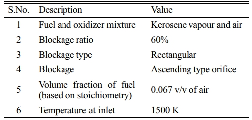
Earlier research has been extensively done on 1D and 2D platforms for extrapolating the effective blockage types, blockage ratio and pulse length. It has been reported that rectangular type blockage placed at three different locations with 60% blockage ratio imitating an orifice type of blockage in ascending order along the length of the tube has been the most effective in creating controlled pulses of thrust with supersonic velocity at the exit and a mean effective pressure aiding in further expansion of the flow [36, 37]. Flow development across cross-sections have to be studied to find an effective topography and design of engine for practical purposes. For this reason, three types of cross-sections i.e. cylinder, square and rectangle, have been selected after extensive analysis of hypersonic flows and the investigation has been done making the assumptions to maintain the consistency of study as shown in Table 1. The simulation is setup for a standard tubular length of one meter and diameter
the laboratories with multiple blockages in the flow stream.
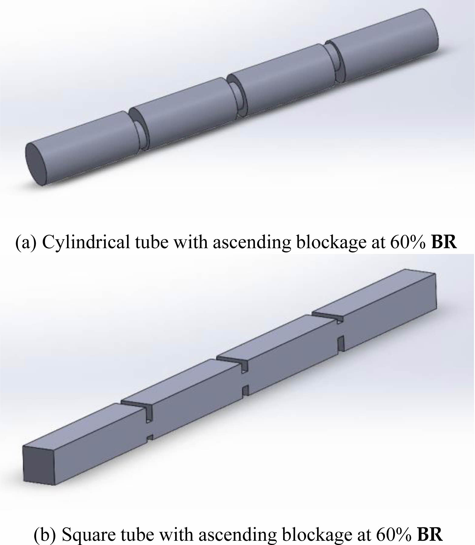
Kerosene vapor and air mixture is considered to imply that the detonation engine model is an air-breathing engine taking the oxidizer from the atmosphere. Blockage ratio exceeding 60% of the cross-sectional area dimension was found to be mitigating the flow velocity and rapid increase of pressure was found in the cavities behind each blockage. Flow jump has been prevalently optimized by using a rectangular type of blockage set up in ascending type of orifice model [37]. Conventional blocking arrangements like springs or ramps positioned in the length of the tube has given positive results but the rectangular orifice blockage has the maximum flow structure efficiency and it has been selected for the The modeling and meshing are done with same scale factor across the cross-sections to maintain dimensional homogeneity and grid consistency is guaranteed by selecting a semi structured mesh for all the models. Fig. 3a and Fig. 3b, depict the geometric models of the square and cylindrical shaped tubes created. The rectangular block was avoided as the square block can further be used to understand the numerical analysis by assuming the side wall of the square tube to symmetric about the lateral axis thereby making the rectangular analysis possible with l/h ratio of 2.
Numerical methods
The model is created in such a way that it is symmetric along the length of the tube across the lateral axis as the overall flow development is clearly visualized and the calculation is summarized for the bodies. Turbulent kinetic energy-dissipation model [k − e] is considered with no effects of wall shear to simulate high-speed controlled detonation flows. Also, the no shear condition signifies no aerodynamic friction caused to the flow-surface interaction in the tubular cross-sections and thereby no heat loss is felt. The premixed combustion of kerosene vapor-air mixture in stoichiometric ratio has been simulated with a high initial temperature of 1500 K. The inlet pressure is varied from minimum to maximum to calculate the critical pressure where maximum effectiveness of the bodies can be found with a chance that different cross- sections performed contrarily at variable pressures. Initial values of kinetic energy function and turbulent dissipation have been found from the relations: of one inch or 25.3 mm. This dimension depicts the standard test dimensions in most of the experimental tests done across
K = 3/2[UI]2 = 4.43×10⁻⁵ m2·s-2
where,
U is mean flow velocity at inlet = 0.15 m·s−1
I is turbulence intensity
cµ= 0.09
I = 0.032
and,
l is Turbulent length scale in m
l = 0.038 dh
l = 0.0019228 m
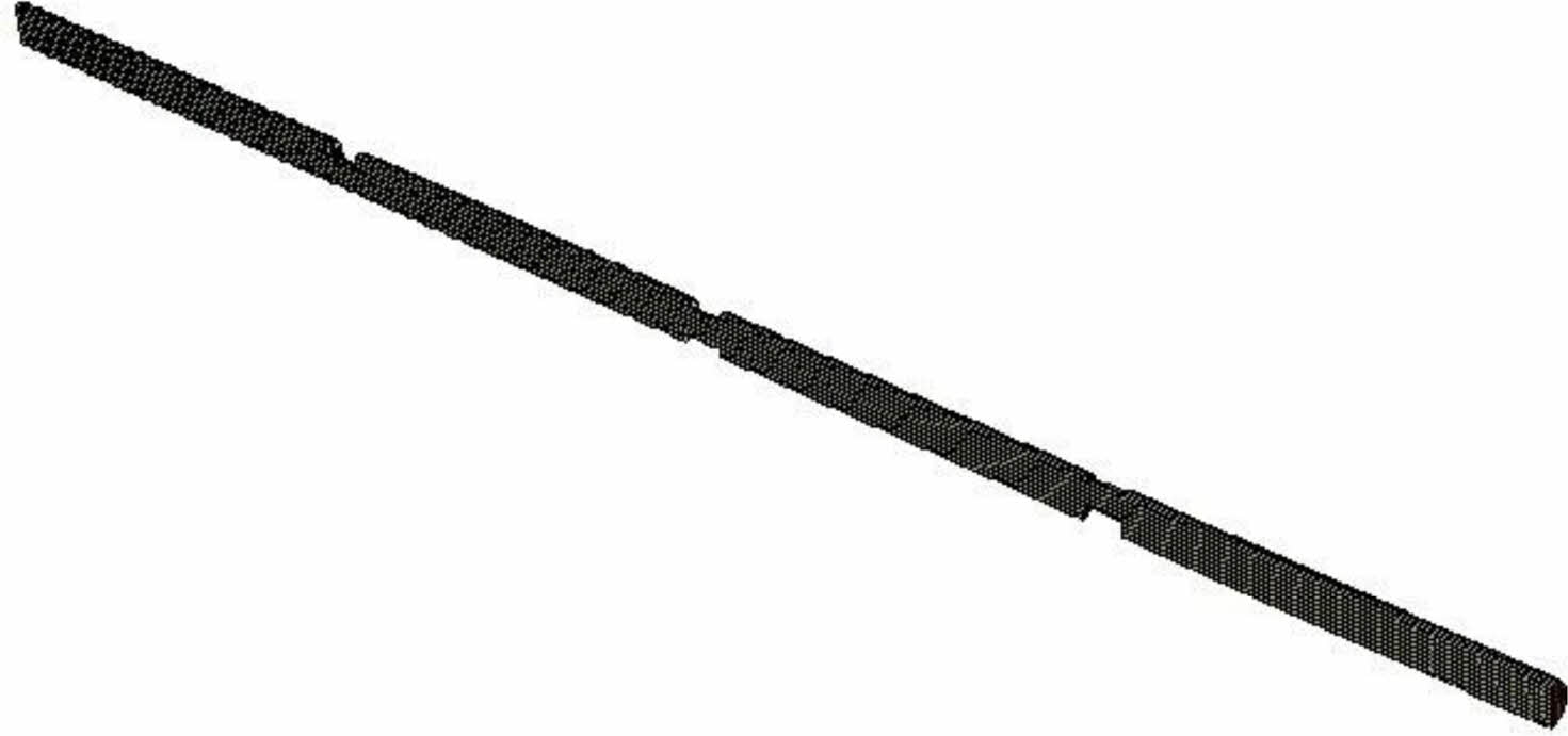
Inlet pressure using a multiphase flow is given as a common boundary condition to analyze the models without disambiguation. The inlet pressure for the multiphase premix has been varied i.e. 10 bar, 50 bar, and 100 bar to calculate the maximum velocity and effective pressure at the exit. The simulation has been done in a finite volume computational fluid solver model and the detailed analysis of the different bodies with relevant results appertained to the cross-sectional geometry to achieve controlled pulsed detonation has been discussed. Fig. 4 depicts a mesh file generated and used to simulate a cylindrical tube cross section where the center plane is considered in symmetry to examine the flow development throughout the pipe surface [38].
Experimental methods
Plain Tube Experiment
Initial design of experiments to validate the claims in CFD analysis were done using plain tube.
The shockwave expan-sion patterns were benchmarked with the numerical analysis and the veracity of the model was established [37].
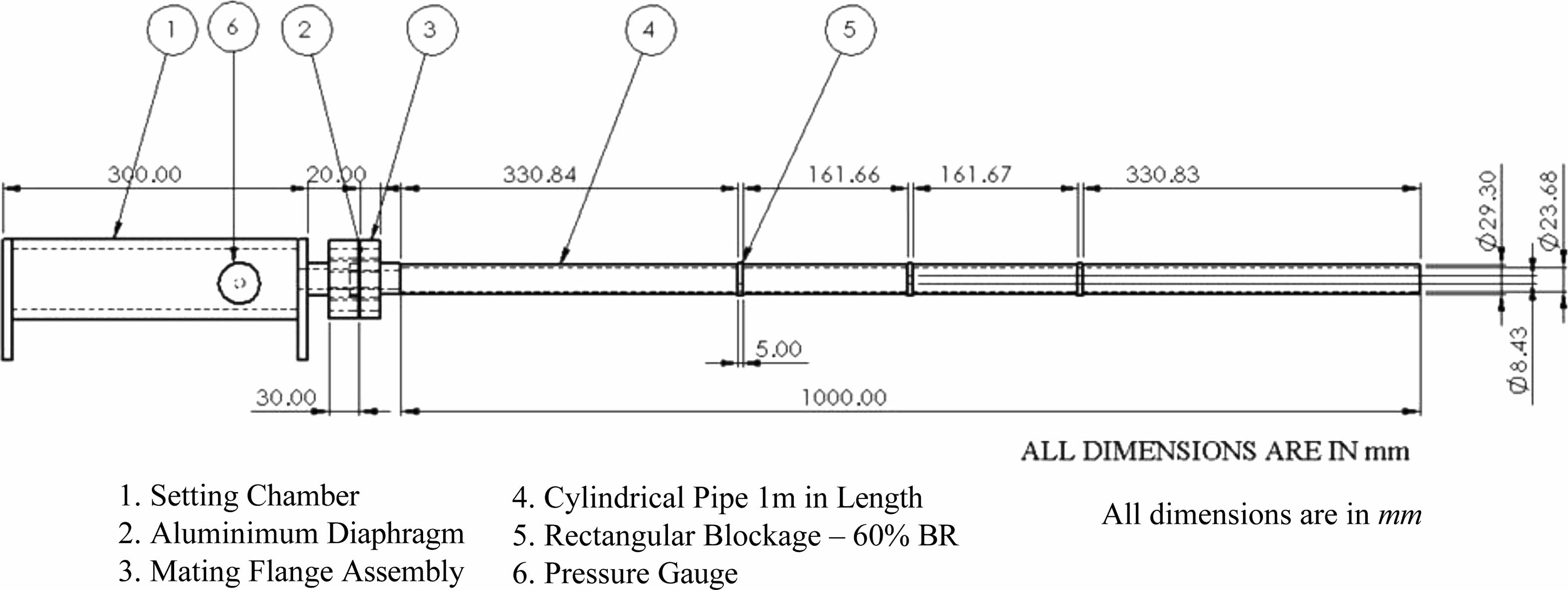
The experimental setup to determine the onset of detonation is shown in the Fig. 5. Fig. 6 illustrates the two cross sections with optimal blockage ratio of 60% drilled at differential heights of the obstacle plates.
Defenition of Optimal Cross-section for Combustor Tube
Initial experimentation was done with a 1 m length plain tube of circular cross section. This formed the basis of design of experiments further and validation of the computational and experimental models. In the second stage of experimentation two different types of cross sections namely circular and square are taken in the jet flow region. As discussed in the numerical analysis that the ascending type of blockages is the most optimal for detonation initiation. To mimic the blockage, the circular pipe is cut at 1/3rd, 1/2nd and 2/3rd positions and a 10 mm thick plate is attached with a hole and a blockage ratio of 60%. In case of square pipes, slits are given at the aforementioned positions and 10 mm thick plates are attached to these slits by weldments.
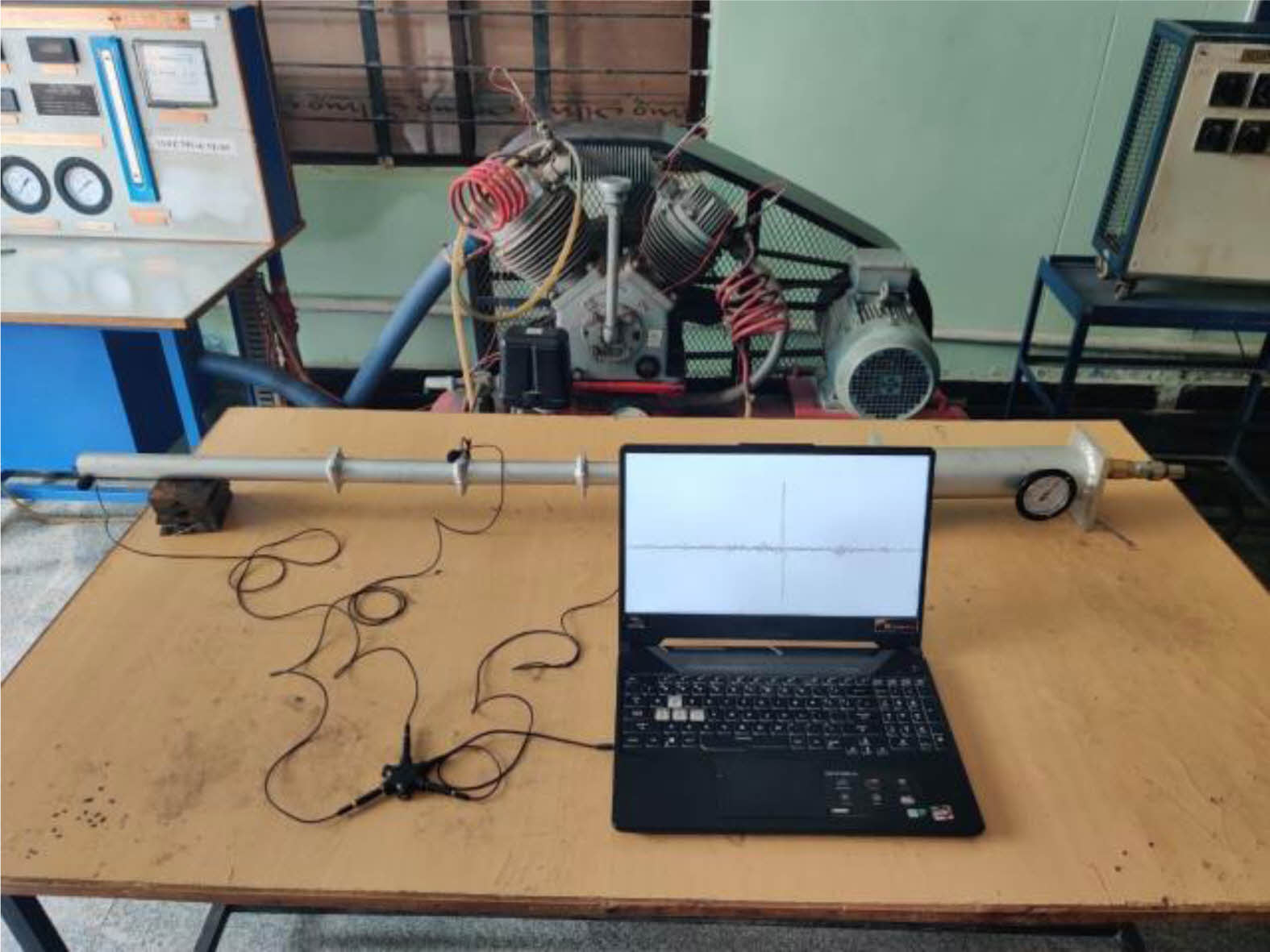
The air is filled in settling chamber with variable pressure controlled by a non-return valve and the blowdown is avoided by the stack of aluminium foil attached as diaphragm in the exit of thrust chamber. The pressure is monitored inside the settling chamber by a bourdon tube mounted on the top of the experimental setup. Indigenously developed acoustic wave pressure measurement instrumental setup is used for recording the pressure output through the different cross sections connected to the computer for calculating the exit velocity for different cross sections and inlet pressure from the blowdown of the settling chamber. Fig. 7 shows a cylindrical cross section with three blockages mounted with 13 layers of aluminium diaphragm. The blowdown causes a spike in the soundwave at the exit of the settling chamber due to the wave pressure increment. A 5-way split recording system is used to record these pulses through multiple experimentation to record the values of the pressure waves and calculate the exit velocity. The computer screen shows clearly the spike in acoustic decibels at the exit of the settling chamber.
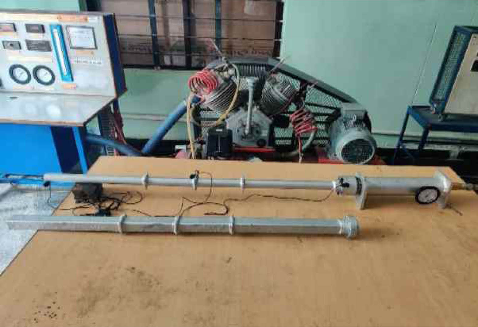
In the plain tube analysis, blowdown pressure is compared to that of the pressure of exit wave and velocity of the flow. In the blockage analysis, the blockage causes the flow to jump to higher velocities and sustain the wave pressure due to the compressibility effect achieved by high pressure injection inside the combustor tube. The two different cross sections used for experimental procedure mounted to the settling chamber is shown in Fig. 8.
|
Fig. 3 Models for numerical analysis. |
|
Fig. 4 Symmetrical half cylinder tube with orifice type blockages and 60% BR meshed in a semi-structured mesh. |
|
Fig. 5 Experimental Layout. |

|
Fig. 6 (a) and (b). Cylindrical tube with blockage positions before the weld, (c) and (d) Square tube with blockage positions before the weld. |
|
Fig. 7 Experimental setup for cylindrical cross section mounted with 13 layers of aluminium diaphragm. |
|
Fig. 8 Illustration of cylindrical and square cross section. |
Numerical results
Models have been created with orifice blockages placed at
three equidistant locations in the overall length of the combustor tubes. This causes the shock wave formation delays due to the sudden change in the cross-section of flow and choking of flow across the blockages easily. In addition, each blockage due to the high-pressure ramming effect of short pulses have effectively increased the output velocity without compromising effective exit pressure to expand the flow further to hypersonic conditions.
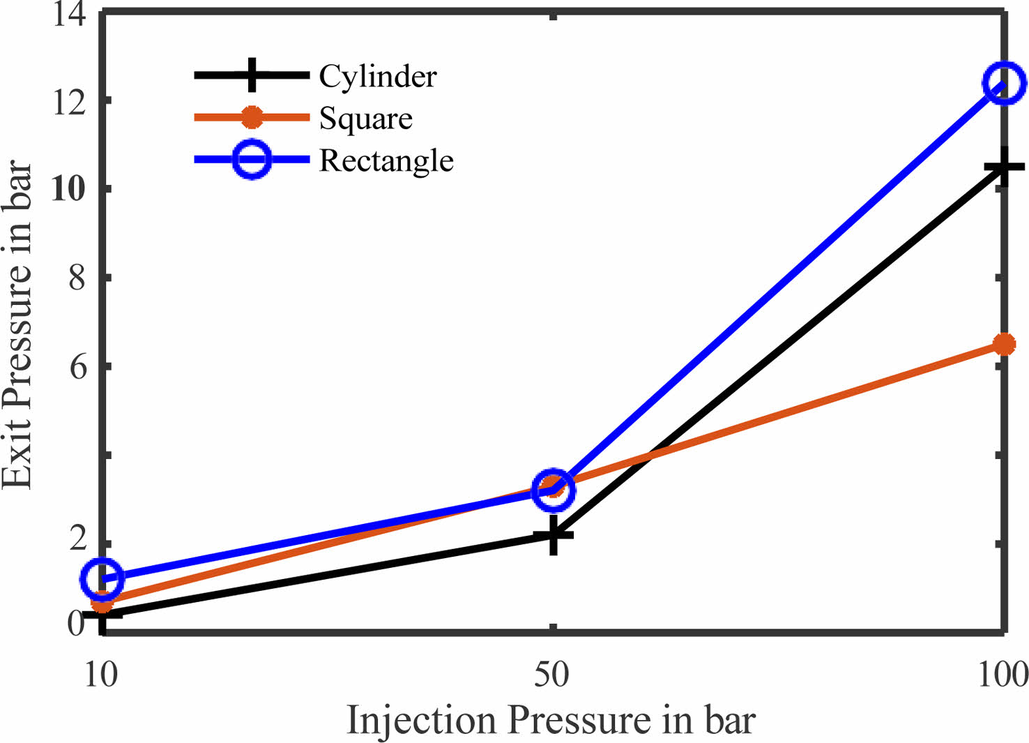
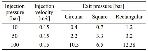
Table 2, shows the variation of exit pressure for various cross section with reference to the onset pressure and minimum initial velocity. The initial temperature is set at 1500 K and the total boundary depict a premixed combustion exhaust or settling chamber from which the flow is released into the tubular section. It shows that the gases expand completely during the overall flow through the tube of several cross-sections. Steady increment of flow pressure at the exit is found across all the cross sections and the cylindrical cross section has the optimal pressure at the exit for any onset pressure and initial velocity. Also, it is to be noted that the maximum exit pressure is observed when using a rectangular type tube with blockages at 12.38 bar with an onset pressure of 100 bar. This type of flow may further be expanded to atmospheric conditions to extract the necessary thrust with the specifically designed nozzle geometry. Further, it has been observed that the cylindrical cross section has a fully expanded flow with reference to the onset pressure covering the entirety of cross-sectional area, whereas, the square and rectangular cross sections mitigate the flow near the surface of the tube and maximum flow occur at the center of the tube. Having intermittent blockages at variable heights forces the flow to jump up to higher speeds and expand completely throughout the length of the tube. Fig. 9 shows the graphical representation of Table 2 and clearly depicts that the characteristic exit pressure of a rectangular cross-section is higher compared to other cross-sections.
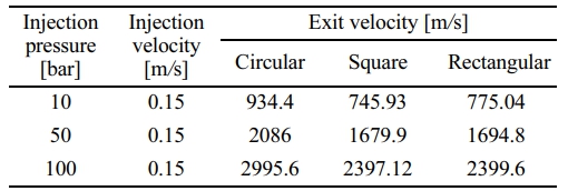
Variation of exit velocity of combustible gas mixtures have been shown in Table 3 and shows that for minimal inlet pressure of 10 bar the maximum velocity of exit is extracted through a cylindrical cross section with blockages.
It is evident from cross referencing the Table 2 with the data that the cylindrical cross-section expands the flow better compared to that of the expansions in square or rectangular sections. Curvature effect may have affected the performance of the sections and hence the mitigation of the flow has been observed in any linear sections having sharp angles at the corners and surfaces. Further, it is also be observed that increasing the pressure beyond 50 bar the increment of exit velocity through any section is not linear. An exponential form may be evolved to say that the velocity at the exit may become stable for any cross-section beyond the maximum scope of expansion through the tube and any further improvement cannot be observed. The point where the exit velocity and thrust become constant may be
designated as the maximum inlet pressure for optimized maximum performance. Pulse detonation engines depend on the pulse length and mass flow rate of the mixture, so maximum endurance with a quantified thrust is capable in lower pressure intakes also. Depending on the application and thrust requirement of particular mission, cross section of the engine may be selected and the critical pressure of 50 bar may be used for effective thrust production with a quantifiable endurance can be achieved. Fig. 10 shows the comparative analysis between inlet and exit velocities and it clearly shows that the cylindrical cross section has maximum performance in terms of the detonation exit velocity but the exit velocities of square and rectangular sections are evenly matched and cannot be ignored completely as the difference in the velocities are comparable and may match other mission requirements.
The most optimized cross-section for a pulse detonation engine based on the study is clearly shown to be a cylindrical cross section comparing the exit velocity and the pressure while the square and rectangular may be used for other applications. Fig. 11 and Fig. 12 shows the velocity and pressure contours of a cylindrical symmetric tube for a maximum pressure of 100 bar at the onset respectively.
The Fig. 12 clearly depicts the incremental velocity schema across the three blockages with maximum velocity at the exit found to be 2995.6 m/s with distinctive shockwave patterns. The high blockage ratio lead to the dark patches in the flow and shows that the turbulent boundary layer is thicker due to the high velocity of expansion through the length of the tube. And it is clearly visible that the flow expands covering the entire exit cross sectional area avoiding any reverse flow and continual thrust. It must be noted that the pulse detonation engine does not wholly depends on continuous thrust but intermittent pulses of specific time duration. Operating beyond the critical pressure may be required to mitigate any backflows and complete expansion of combustion product through the tube for effective thrust production and management.
Experimental results
Plain tube experiment
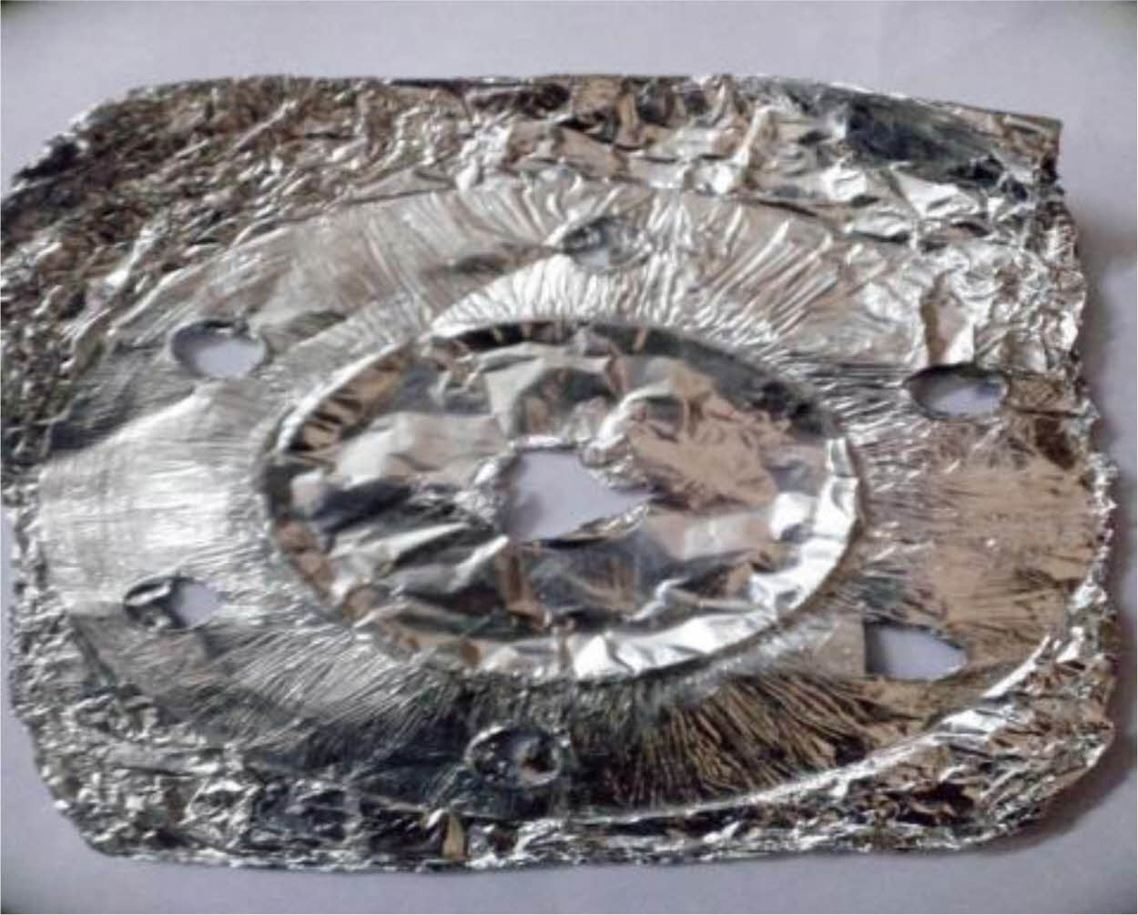
Figure 13 shows a sample of the ruptured diaphragm, which shows that the diaphragm rupture is matching with the delivery tube and no material loss occurs, implying that the multilayer aluminum foil diaphragm has better structural integrity than composite layered diaphragms and is better suited for hot flow detonation initiation tests.
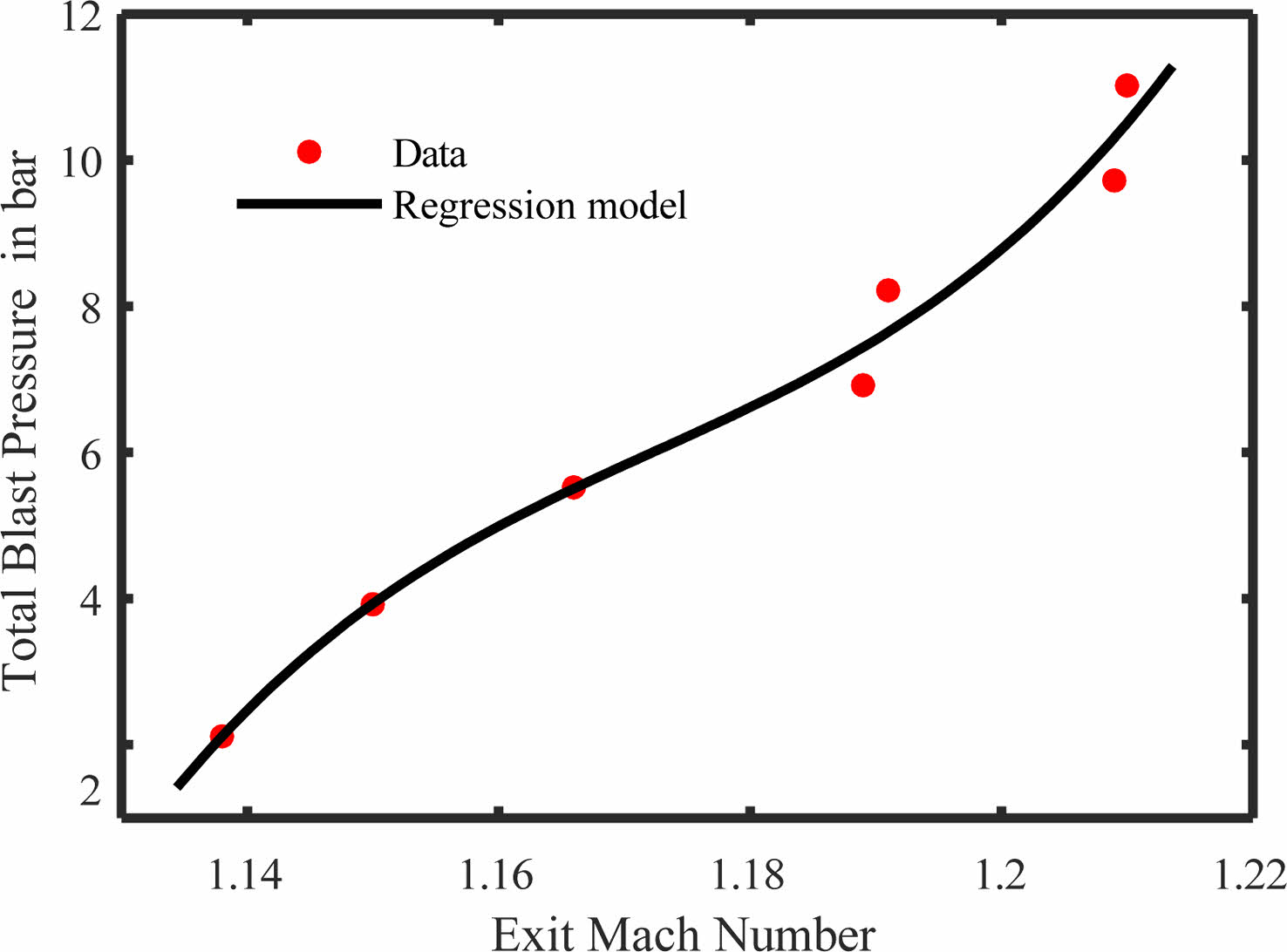
Figure 14 depicts the relationship between exit Mach number and blast pressure with trend showing a polynomial equation of third order for calculating the exit Mach number at any given blast pressure.
A steady growth of pressure in the settling chamber is required for the isentropic expansion of gases at the exit with high velocities. 26 layers of aluminium foil diaphragm compressed in a UTM was used to sustain a settling chamber gauge pressure of 10 bar. The exit velocity under such experimental conditions were observed to be around 476 m/s.
Optimization of cross-section
For the convenience of test a circular and square tube were selected and the blockages were placed in the 1/3rd, 1/2nd and 2/3 positions of the tube length with a blockage ratio
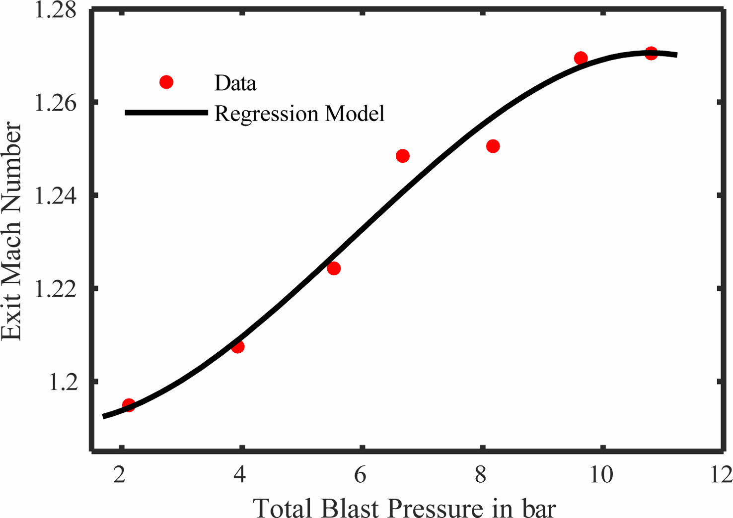
optimized to 60% A/A. The trends of exit velocities across both the section is as shown in Fig. 15 and 16.
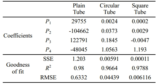
The trend graphs are modeled using regression modeling and used third order polynomial equations. The coefficients of equations and goodness of fit for all three-cross section in given in Table 4. The R-square values are standardly above 90%. The regression gain is constantly high stating that the depending variables in this equation pressure and Mach number variance is under control limits and the polynomial can be used as a predicting method for further Mach numbers as in reference to that of the burst pressure.
The R2 values for different degrees of polynomial equation for all three cross sections is shown in Table 5. The R2 value is increasing with the degree of polynomial. Hence, it will be concluded that higher degree of polynomial equation gives more accurate results.
Comparative analysis
A comparative study between the numerical and experimental values have been studied to gain an understanding of the error function between experimental and numerical study. The numerical study yields 14% more result than that of the experimental results. This claim can be substantiated by the means of understanding the boundary physics between the numerical and experimental analysis. Experimentation is done only in cold flow media and there is no introduction of fuel term in case of risk factors and other facility related issues. That does not mean to completely ignore the experimental results as it validates the claim that the numerical simulations done can be downscaled at the rate of 14% to improve the accuracy of the data set. Which leads to a conclusion that the data set erf value of 14% is acceptable compromise. Further, each of the experimental data has been conformed with a 3rd degree polynomial to assist in the calculation of expected speed at the exit with relevance to the burst pressure from the diaphragm.
|
Fig. 9 Variation of Exit Pressure with Injection Pressure. |

|
Fig. 10 Variation of Exit Velocity with Injection Pressure. |

|
Fig. 11 Expansion of flow across a cylindrical tube with 100 bar injection pressure. |

|
Fig. 12 Velocity contour through a cylindrical tube with blockages with 100 bar injection pressure. |
|
Fig. 13 13 Layers of Aluminum foil blasted at 6.213bar Gauge Pressure. |
|
Fig. 14 Polynomial regression model between blast pressure and exit Mach number in a plain tube. |

|
Fig. 15 Polynomial regression model between blast pressure and exit Mach number in a circular tube with block-ages. |
|
Fig. 16 Polynomial regression model between blast pressure and exit Mach number in a square tube with block-ages. |
|
Table 3 Variation of combustible gas mixture velocity for various cross section at exit. |
Based on the study, the following conclusions were derived for the effective operation of pulse detonation engines.
1) Cylindrical cross section with rectangular type of blockage having blockage ratio of 60% of the area of tube arranged in a ascending order evenly spaced thrice over the length of the tube would the most effective and optimized cross section for a working model of pulse detonation engine.
2) The maximum velocity at exit has been found to be 2995.6 m/s for an onset pressure of 100 bar in a circular cross section and corresponding exit pressure recorded is 10.5 bar.
3) Beyond the pressure of 50 bar the velocity increment across all cross-sections become exponential inciting the response that the critical pressure of operation for any cross section would be optimally set.
4) Performance of other cross sections are satisfactory but the most optimized solution may be from the circular cross section only, leading to the argument that the curvature corrections in other sections may be a path for improvement for salvaging design parameters based on applications.
5) Cold flow experimental study has yielded corroborative results in comparison to the numerical study. A comparative analysis has been done to understand the relationship between both models and shows a 14% variation of experimental values. This shows that the numerical results can be downscaled by 14% to match the dataset.
- 1. T. Endo and T. Fujiwara, T. of Japan Soc. Aero. Space Sci. 44[146] (2002) 217-222.
-

- 2. S. Yungster, K. Radhakrishnan, and K. Breisacher, Comb. Thy and Mod. 10[6] (2013) 981-1002.
-

- 3. P. Srihari, M.A. Mallesh, G. Prasad, B.V.N. Charyulu, and D.N.N. Reddy, Def. Sci. J. 65[4] (2015) 265-271.
-

- 4. F. Ma, J.Y. Choi, and V. Yang, J. Prop. Power. 21[4] (2005) 681-691.
-

- 5. S. Yungster, 41st Aerosp. Sci. Meet. Exhi. (2003).
-

- 6. D. Allgood, E. Gutmark, J. Hoke, R. Bradley, and F. Schauer, J. of Prop. and Power. 24[6] (2008) 1317-1323.
-

- 7. A. Thattai, Thes. Diss. (2010).
- 8. M.R. Nalim, Z.A. Izzy, and P. Akbari, Shoc. Wav. 22[1] (2012) 23-38.
-

- 9. Vizcaino, Jeff. ERAU Dissert. Thes. (2013).
- 10. D.M. Valli and T. Jindal, Int. J. Inno. Res. Techn. Sci. Eng. 3[4] (2014) 11229-11237.
- 11. Y. Wu and J.H. Lee, Comb. Flame. 162[6] (2015) 2660-2669.
-

- 12. N. Gopalakrishnan and D Wilson, AIAA Join. Prop. Conf. (2018).
-

- 13. G.B. Goodwin and E.S. Oran, Comb. Flame. 197 (2018) 145-160.
-

- 14. Y.A. Poludnenko, J. Chambers, Kareem Ahmed, N. Vadim, Gamezo, and D.T. Brian, Sci. 366[6465] (2019).
-

- 15. S.K. Soni, A. Singh, M. Sandhu, A. Goel, and R.K. Sharma, Int. J. Emerg. Technol. Adv. Eng. 3[3] (2013) 458-464.
- 16. M.R. Amin, H.Z. Rouf, and J.L. Cambier, J. Mech. Eng. 51[7-8] (2005) 484-490.
- 17. V.N. Tangirala, A.J. Dean, N. Tsuboi, and A.K. Hayashi, Aerosp. Sci. Meet. Exh. (2007).
-

- 18. Y. Shao, M. Liu, and J. Wang, Chinese J. Aero. 23[6] (2010) 647-652.
-

- 19. E. Wintenberger, J.E. Shepherd, and J. Propul, Power. 22[3] (2006) 593-603.
-

- 20. K. Kailasanath and G. Patnaik, Proc. Combust. Inst. 28[1] (2000) 595-601.
-

- 21. S.M. Frolov and V.S. Aksenov, Dokl. Phys. Chem. 416[1] (2007) 261-264.
-

- 22. C. Johansen and G. Ciccarelli, J. Loss Prev. Process Ind. 26[4] (2013) 571-585.
-

- 23. S.M. Frolov, V.S. Aksenov, and I.O. Shamshin, Russ. J. Phys. Chem. 2[5] (2008) 759-774.
-

- 24. S. Otsuka, M. Suzuki, and M. Yamamoto, J. Therm. Sci. 19[6] (2010) 540-544.
-

- 25. F. Zheng, A.V. Kuznetsov, W.L. Roberts, and D.E. Paxson, Jt. Prop. Conf. Exh. (2009).
- 26. H.H. Zhang, Z.H. Chen, X.H Sun, X.H Jiang, and Li. Baoming, Comb. Sci. Technol. 183[10] (2011) 1069-1082.
-

- 27. L. Bachman, G.B. Goodwin, and K. Ahmed, Prop. Eng. For. (AIAA). (2019).
-

- 28. C.L. Bachman and G.B. Goodwin, Comb. 223 (2021) 271-283.
-

- 29. R. Kaplan, A. Ozgen, and E.S. Oran, Comb. Thy. Mod. 23[1] (2019) 67-86.
-

- 30. T.A. Kaemming, M.L. Fotia, J. Hoke, S.A. Schumaker, and F.R. Schauer, AIAA Sci. Tech. For. (2020).
-

- 31. T.H. Yi, D.R. Wilson, and F.K. Lu, Aerosp. Sci. Meet. Exh. (2006).
-

- 32. W.A. Stoddard, M. Mihaescu, and E. Gutmark, Jt. Prop. Conf. Exh. (2010).
-

- 33. T. Xiao-ming, J.Z. Zhang, and X.T. Wang, Eng. Appl. Comput. Fluid Mech. 5[4] (2011) 499-505.
-

- 34. X. He and A.R. Karagozian, J. Sci. Comput. 19[1-3] (2003) 201-224.
-

- 35. F. Ma, J.Y. Choi, and V. Yang, J. Propuls. Power. 24[3] (2008) 479-490.
-

- 36. S. Srikrishnan, V. Jayakumar, and P.K. Dash, Adv. Stru. Sys. Mat. (2020).
-

- 37. S. Srikrishnan, T. Shaafi, and P.K. Dash, IOP Conf. Ser.: Mater. Sci. Eng. 992 (2020).
-

- 38. S. Srikrishnan, P.K. Dash, and V. Jayakumar, MATEC Web Conf. 172[02006] (2018) 1-8.
-

- 39. T. Ganesan, K. Murugan, R. Prakash, N. Kathiravan, and J. Ceram. Process. Res. 23[5] (2022) 625-628.
-

- 40. C. Ozturk and T. Demircan, J. Ceram. Process. Res. 21[4] (2020) 433-441.
-

 This Article
-
2023; 24(5): 762-771
Published on Oct 31, 2023
- 10.36410/jcpr.2023.24.5.762
- Received on Apr 7, 2023
- Revised on Jul 20, 2023
- Accepted on Jul 28, 2023
 Services
Shared
 Correspondence to
- S. Srikrishnan
-
Department of Mechanical Engineering, Saveetha School of Engineering, Saveetha Institute of Medical and Technical Sciences, Chennai 602105, India
Tel : +91 97040 26988 Fax: 044 2680 1050 - E-mail: srikrishnans765@gmail.com



 Copyright 2019 International Orgranization for Ceramic Processing. All rights reserved.