- Preparation and characterization of Alumina / Magnesia / Zirconia / Graphite refractory composites using response surface methodology
Maryam Abolfazli and Mohammad Hossein Paydar*
Department of Materials Science and Engineering, School of Engineering, Shiraz University, Shiraz, Iran
This article is an open access article distributed under the terms of the Creative Commons Attribution Non-Commercial License (http://creativecommons.org/licenses/by-nc/4.0) which permits unrestricted non-commercial use, distribution, and reproduction in any medium, provided the original work is properly cited.
In the present study, Alumina/ Magnesia/ Zirconia/ Graphite (AMZG) refractory composite was fabricated and its physical, mechanical and chemical properties were investigated. The preparation of AMZG refractory composite was modeled and optimized by using Central Composite Design (CCD). Among all factors, zirconia content (0-5 wt.%), magnesia content (0-10 wt.%) and graphite size (fine and coarse grained) were selected. The factors were varied in 5 levels and the responses were fitted by quadratic regression model. Statistical data showed that the highest relative density, modulus of rupture and oxidation resistance were obtained by fine grained graphite at zirconia and magnesia of 3.312 wt.% and 4.075 wt.%, respectively. Quantitative analysis of the X-ray diffraction (XRD) pattern by Rietveld method revealed that the optimal sample composition included 44.2, 26.1, 10.3, 4.2 and 15.2 wt% of corundum, cordierite, spinel, zirconium oxide and graphite phases, respectively. The result of XRD is confirmed by Differential Thermal Analysis (DTA). The oxidation resistance (at 900 oC) of the best specimen was investigated
Keywords: Alumina/Magnesia/Zirconia/graphite composites, Refractories, Microstructure, Mechanical properties, Oxidation resistance, Response surface methodology
The rising development of metallurgical products has increased the demand for refractory materials. Among the refractories used in metallurgical industries, especially the steelmaking, oxide / graphite composite refractories play a major role due to their thermomechanical and thermochemical properties [1]. Since alumina is one of the most common and oldest known high temperature ceramics [2], perhaps the first and most important basic composition of these refractories can be considered alumina / graphite refractories that are of special impor- tance in improving the quality of steel making process, especially continuous steel casting [3]. Despite the advantages of Alumina / graphite refractories such as high strength, high thermal conductivity, low thermal expansion, high thermal shock resistance and resistance to molten slag, they are facing with a few problems such as oxidation of graphite, physical and chemical erosion, etc. [4]. Antioxidants [5] and high purity substances [6] can be used to solve these problems. Another solution is to prepare composite refractories using other high temperature oxides. Accordingly, refractories containing other oxides such as magnesia / graphite [7] and zirconia / graphite [8], etc. were developed.
Recently, the simultaneous use of several oxides in the refractory composition has led to the formation of another class of refractories called alumina-magnesia-graphite (AMG) [9] and alumina-zirconia-graphite (AZG) [10] refractories. These classes of materials have attracted a lot of attention and researchers have studied the parameters affecting their properties. Muñoz et al. carefully analyzed texture, composition and micro- structure of three commercial AMC bricks and studied their dimensional change and thermal and mechanical properties [11]. They also evaluated the slag corrosion using experimental data and thermodynamic simulation [12]. Klewski et al. studied the effect of different alumina sources with different grain size on the final properties of AMC bricks [13]. Mukhopadhyay et al. discussed on the effect of MgO grain size and found that spinelizarion reaction and permanent linear change of refractory are directly related to the total surface area of magnesia [14]. Babakhanova and Aripova changed the corundum, talc and graphite amount and showed that the maximum slag strength is related to the composition with the lowest porosity [15]. Yu et al. investigated the effect of manufacturing parameters such as pressure, particle size distribution, sintering temperature and time on the final properties of AZG refractories, and they found that the use of alumina with high ratio of coarse to fine particle has led to an increase in density [16-17].
The notable issue in all these studies is the use of the one-factor at a time method. In this method, the inter- action of the parameters with each other is avoided. To address this shortcoming, statistical methods and multi-factor studies have been designed, which the response surface methodology (RSM) is one of the most common [18]. In the present project, alumina / magnesia / zirconia / graphite composite has been prepared and the effect of zirconia content, magnesium content and graphite particle size on the physical (density and strength) and chemical (oxidation) properties of the fabricated com- posites have been investigated using RSM.
Alumina / Magnesia / Zirconia / Graphite (AMZG) re- fractory composite was prepared using commercial grade of raw materials. The composite composition has been selected according to studies by other researchers [19-21] (Table 1). Certain amounts of alumina (Tabular, white and brown fused alumina), fused silica, silicon, phenolic resin (novolac resin) were mixed with different amounts of magnesia and partially stabilized zirconia (t-zirconia) and fine / coarse grained graphite. All materials were wet milled by planetary ball mill for 1 h with absolute ethanol as dispersion medium. After drying, mixed powders were poured into latex mold and were vacuumed. Ultimately the powders were iso- statically pressed by applying 850 bar pressure and sintered at 1400 oC for 8 h under a reducing atmosphere.
Central composite design (CCD) was employed for the design of experiment. In this method, 3 main levels are considered as low (-1), intermediate (0) and high (+1) values. In addition to these three levels, alpha (±α) is also defined as the distance from the center point, which its value depends on the number of parameters. A value of 2 was given to alpha to cover the entire range of the experiment as introduced in Table 2. The design had a total of 24 runs including 4 factorial points, 4 axial points and 4 replicates at the center points which duplicated for each level of categorical factor. The complete quadratic model for 3 variables CCD is as below:

where Y is the response; b0 is the model constant, bi is the linear coefficients, bii the quadratic coefficients and bij is the interaction coefficients, xi and xj are indepen- dent variables. There were five levels for numeric factors (ZrO2 and MgO) and two levels for categoric factor (graphite).
Bulk density and modulus of rupture (MOR) of the sintered specimens were measured according to ASTM-C-20 and ASTM-C-133standards, respectively. The char- acteristics of the prepared composite were studied by means of X-ray diffraction (XRD) (INEl, EQUINOX 3000). Isothermal oxidation tests were carried out at 900 oC for 2 h according to ASTM-863 standard and weight losses were reported.
Modeling
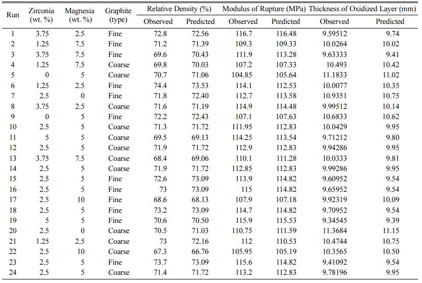
In accordance with central composite design proce- dure, 24 experiments were performed to evaluate the effect of 3 factors and their interactions on density, strength and oxidation resistance of the AMZG refractory composite. Experimental and predicted values are introduced in Table 3.
Eq. (2-4) are a coded second order polynomial equation based on experimental results, provided by Design Expert software version 7, which were appro- priately fitted on the empirical data:
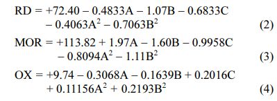
The positive/ negative effect of each variable on the response can be obtained from its coefficient sign [22]. The actual equations (Eq. 5-10) are as follows:
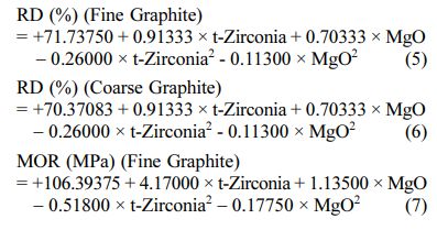
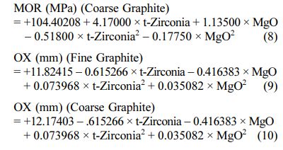
These models can be used to calculate the response within the specified range. Analysis of variance of the reduced quadratic model for each response presented in Tables 4-6. Table 5
The Model F-values of 44.90, 58.92 and 35.52 for density, modulus of rupture and oxidation layer, respectively, imply that the models are significant. P-values less than 0.001 indicate that there is only a 0.01% chance that a F-value this large could occur due to noise. The lack of fit F-value of 2.36, 2.60 and 2.90 imply that there are 15.00%, 12.50% and 10.04% chance that a lack of fit F-value could occur due to noise for density, modulus of rupture and oxidation layer, respectively. Fit statistics are shown in Tables 7-9. Table 8
As can be seen, the predicted R2 of each model is in reasonable agreement with its adjusted R2; i.e. the difference is less than 0.2. The adequate precision, which measures the signal-to-noise ratio, also indicates that the models can be used to navigate the design space.
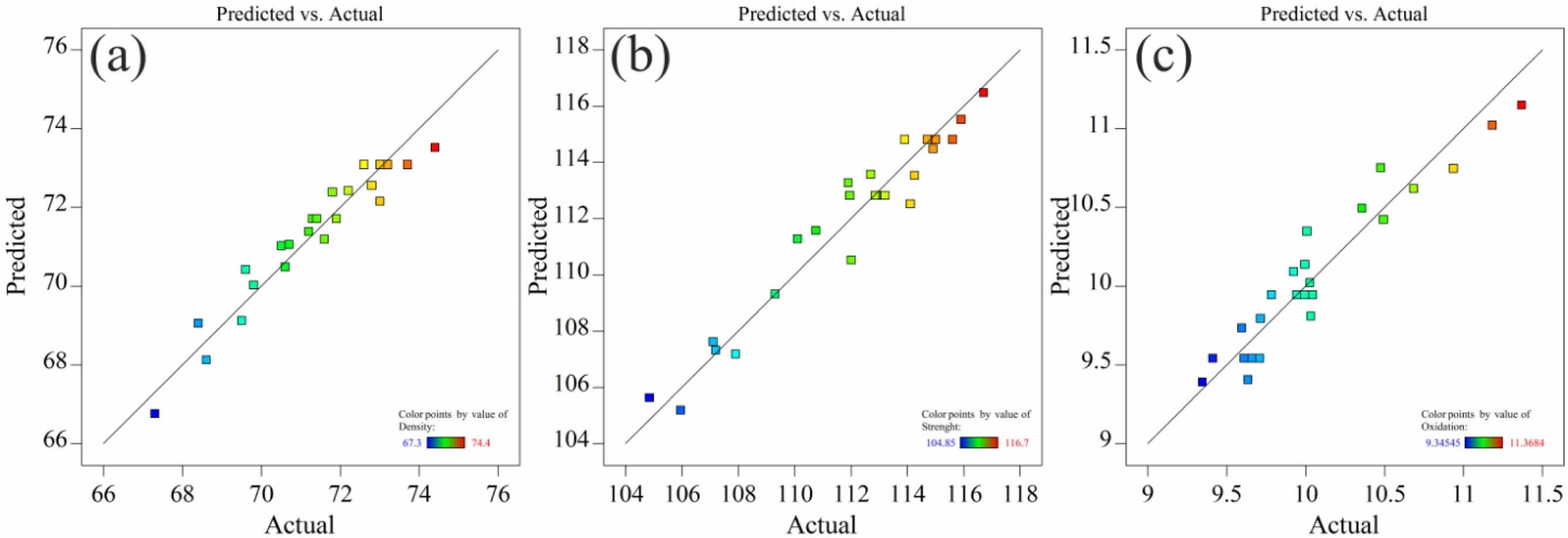
The normal probability plots of models are depicted in Fig. 1. Substantive departures from normality could be identified by these plots.
As can be seen in Fig. 1, the data are close to the straight line, meaning that the data is distributed almost normally, which proves the suitability of the proposed model. In the following, the proposed model will be investigated in more detail.
Density
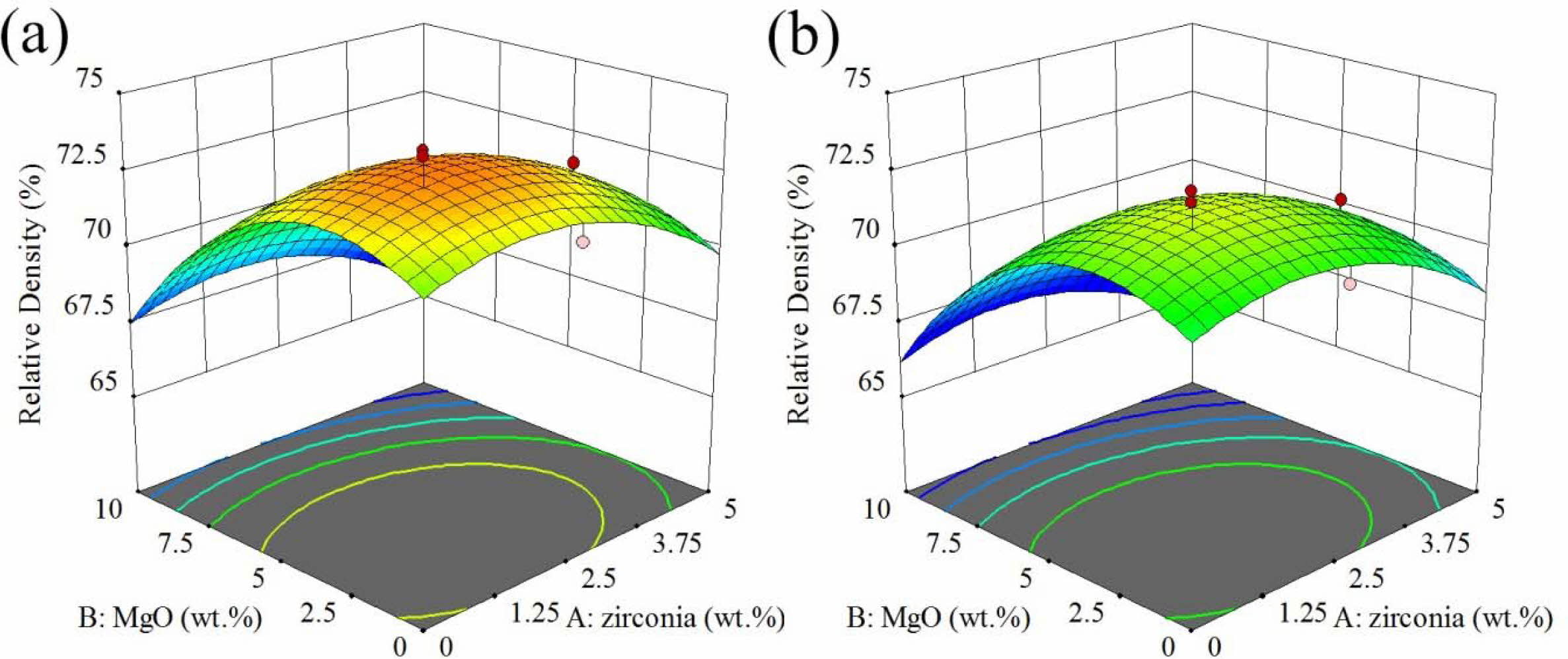
The response surface and contour diagram for the relative density of AMZG refractory composites as a function of t-zirconia and MgO content (wt.%) is presented in Fig. 2.
In general, the presence of graphite particles reduces the densification and shrinkage and prevents the con- solidation of composite during sintering. This effect causes the closed porosities to not move, resulting in a decrease in density, an increase in apparent porosity and the water absorption with graphite content [23]. It is observable in Fig. 2 that the use of fine grained graphite leads to higher value of response. The presence of large particles causes problems in powder packing [24] because it prevents the particles from getting closer to each other and thus reduces the accumulation density [25].
As can be seen, as the amount of magnesium increases, the density increases to a maximum point and then decreases (at a constant amount of zirconia). The increase in density can be due to the formation of cordierite, but further spinel formation and the resulting expansion (about 8%) results in decreasing the density [26]. On the other hand, at a constant amount of magnesia, increasing the amount of zirconia reduces the density again due to the acceleration of spinel phase formation by zirconia [31].
Modulus of rupture
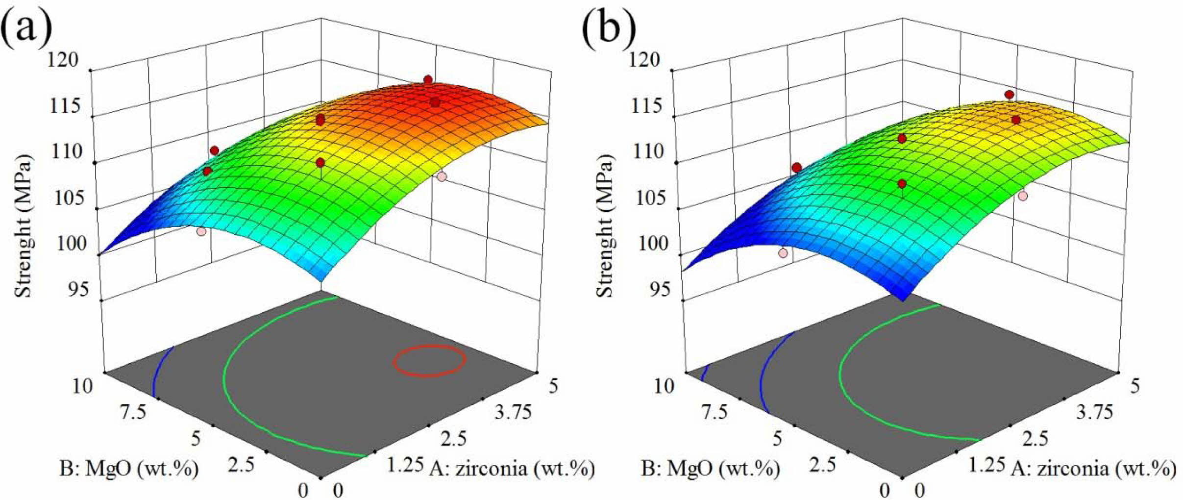
The response surface and contour diagram for the modulus of rupture of AMZG refractory composites as a function of t-zirconia and MgO content (wt. %) for the samples including fine and coarse graphite are presented in Fig. 3.
As it can be seen, the composite containing fine-grained graphite shows greater strength. This may be because smaller particles have a higher surface area than larger particles, providing better stress transfer, which leads to enhancement in strength [27]. According to boundary strengthening in Hall-petch relation, the reduction in particle size leads to a decrease in grain size and consequently an increase in grain boundary, which eventually increases the strength of the composite [28].
It is shown that the strength of the composite at a constant value of zirconia behaves similarly to the density. It increases with the initial increase of magnesia to the maximum state, but further increase leads to a decrease in strength which is due to volumetric expansion cracks due to spinel formation (about 8%) [29]. On the other hand, zirconia constantly increases the strength, which may be due to the predominance of the stress-induced phase transformation toughening mechanism over crack growth [30]. Phase transformations of zirconia as well as its effect on increasing spinellisation lead to a decrease in densification, but its positive effect on mechanical properties cannot be ignored [31].
Oxidation
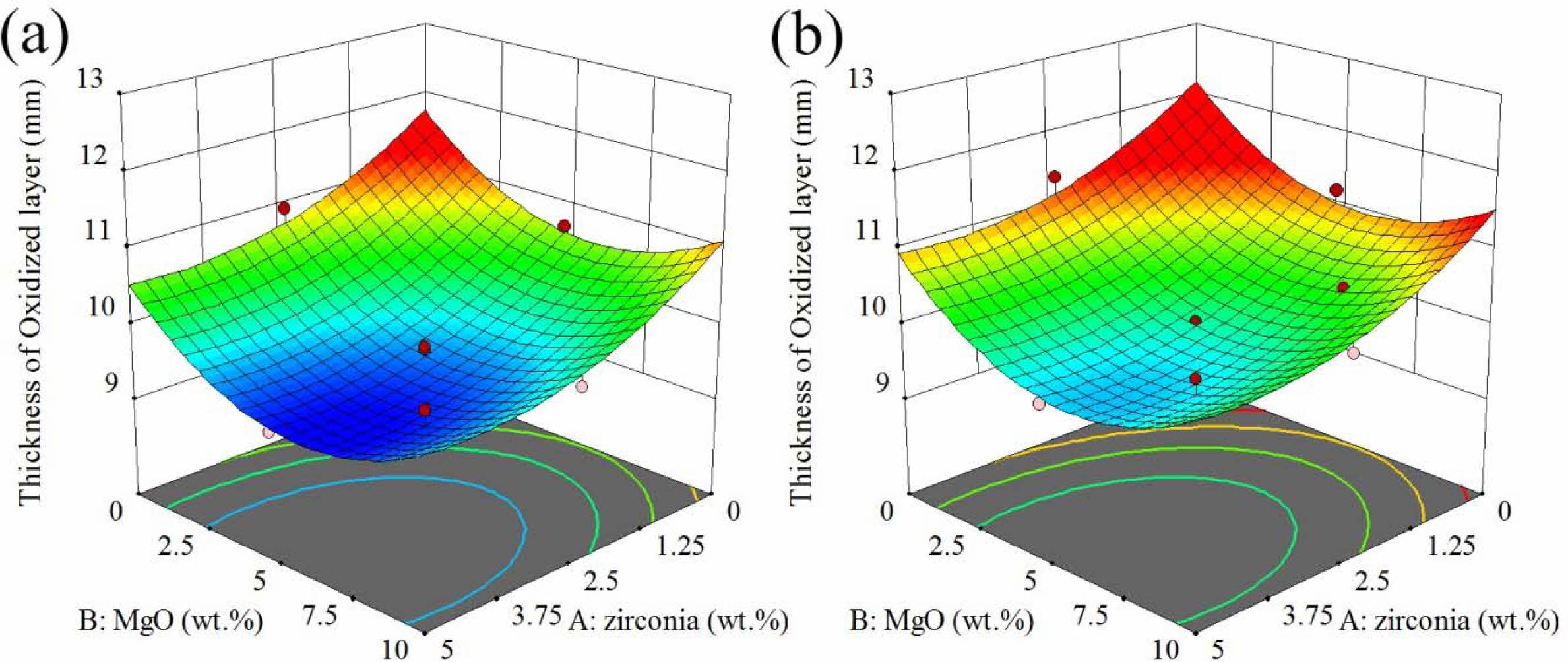
The response surface and contour diagram for the oxidation of AMZG refractory composites as a function of t-zirconia and MgO content (wt.%) is presented in Fig. 4.
Fig. 4 shows that the oxidation behavior of the com- posite is the opposite of the density and strength, so that the specimens containing coarse-grained graphite has shown a greater response. This can be attributed to the high porosity of the specimens, which allows oxygen to penetrate easily. It is worthy to notice that in the case of density and MOR, higher responses are favorable, but in the oxidation thickness, lower values, showing more oxidation resisatnce, are desirable. Based on the Chika et al. report, coarse-grained graphite has better oxidation resistance than fine-grained graphite [32]. But in this case, the composite containing coarse-grained graphite showed lower oxidation resistance, which can be attributed to the decrease in density (Fig. 2) and increase in porosity, which is required for the oxygen penetration.
As it can be seen in Fig. 4, the oxidation decreases with increasing zirconia and magnesium. Two important issues need to be considered here. First is that ZrO2 and MgO are electron donors, which prevent oxidation by stabilizing the electron distribution of the graphite structure, where alumina behaves in the opposite way and is an electron acceptor [33]. Second issue is that, based on nature of the materials, alumina has little permeability to oxygen, while compounds with a fluorite structure such as ZrO2 are highly permeable to oxygen [34]. Regarding these facts, it can be concluded that due to the high porosity of the specimens, the inherent impermeability of the material does not play a decisive role in oxidation resistance and the former reason is more effective. Thus, the maximum oxidation occurred in the region, which is free of magnesia and zirconia.
Optimization of the model
As can be seen in the Figs. 2 to 4, the maximum relative density and modulus of rupture and the minimum of oxidation are not in the same area. Hence, optimal conditions must be found.
Based on the numerical optimization, the best result is at t-zirconia of 3.267 wt.%, MgO of 4.101 wt.% and for using fine grained graphite. The predicted point has relative density of 72.93%, modulus of rupture of 116.157 MPa and oxidation layer thickness of 9.486 mm, which its desirability is about 89%.
Validation of the model
The best result was checked empirically as a comple- mentary test. The experimental results for the best point were 70.32 %, 109.12 MPa and 9.46 mm for relative density, modulus of rupture of and oxidation layer thickness, respectively, which showed a good agreement between experimental and predicted values indicating competency of proposed model.
Characterization of the optimum
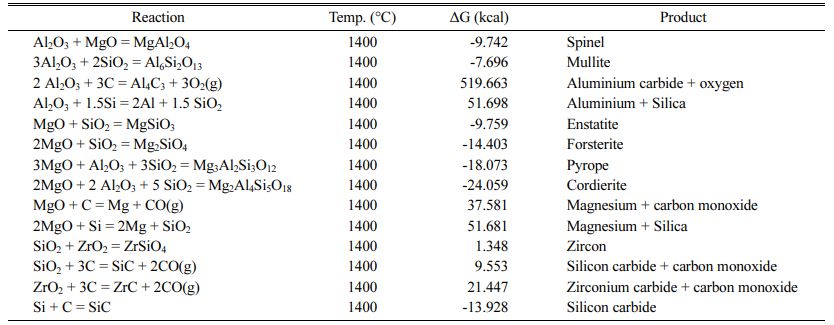
The physical properties of the best specimen were characterized by XRD, DTA and SEM analysis, which are discussed below. Some reactions that may occur between raw materials are also illustrated in Table 10 and their change in free Gibbs energy is calculated.
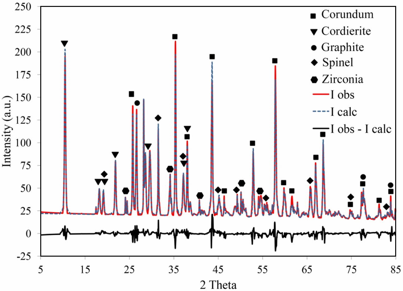
As can be seen, the changes in standard Gibbs free energy for the formation of spinel, mullite, enstatite, forsterite, pyrope, cordierite and silicon carbide are negative. Among of all the reactions, the standard Gibbs free energy of the cordierite formation is more negative than the other reactions at 1400 oC. Accordingly, first the cordierite phase is completely formed [35]. The binary reaction between MgO-Al2O3 and MgO-SiO2 has approximately the same change in standard free energy change. According to the Sembiring et al. studies, spinel formation is most likely as a result of diffusion between alumina and magnesia [36]. The spinel for- mation reaction starts above 1050 oC and peaks at 1600 oC. The presence of carbon hinders the spinelization reaction, while zirconia accelerates it [26]. Silicon carbide formation also has negative standard Gibbs free energy. Finally, X-ray diffraction analysis has been applied in the investigation of phase formation. XRD pattern of the best composition is shown in Fig. 5.
As shown in Fig. 5, the detected phases were corundum (JCPDS card No. 96-900-9675), cordierite (JCPDS card No. 96-900-5807), spinel (JCPDS card No. 96-900-2850), zirconium oxide (JCPDS card No. 96-230-0297) and graphite (JCPDS card No. 96-110-0004). The amount of corundum, cordierite, spinel, zirconium oxide and graphite is 44.2, 26.1, 10.3, 4.2 ad 15.2 wt.%, respectively. The above values were obtained with the aid of the Rietveld method, carried out until the goodness of fit values (GOF) reached about 0.19, which is considered a satisfactory value to reveal the real phase composition. Different plots produced by refinement using the Rietveld method also reveal a reasonable fit between the observed and the calculated plot, demonstrating the usefulness of the method for calculating the quantity of phase composition in the process. Although silicon carbide formation is thermodynamically feasible (Table 10), it is not detected in XRD pattern, meaning that silicon carbide was not formed or its amount is neglectable. The formation temperatures of the phases and the inter- actions occur is discussed in more detail considering the results obtained by DTA analysis.
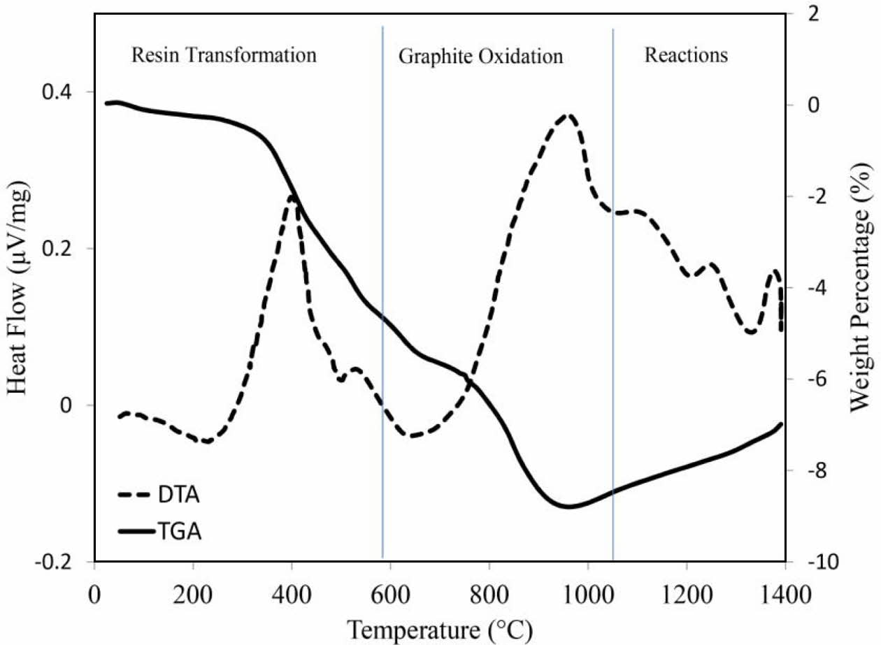
Fig. 6 shows simultaneous thermal analysis (STA) of the optimum sample. The DTA graph shows exothermic peaks below 600 oC that are attributed to the pyrolysis of resin and the oxidation of residual carbon [37]. This event is associated with a weight loss of about 5%. Oxidation of graphite occurs at around 1000 oC, which is accompanied by 4% weight loss. The exothermic peak above 1000 oC is characteristic of spinel formation [38], while the exothermic peaks above 1200 oC and below 1400 oC are due to the solid state formation of μ and α cordierite, respectively [39]. As can be seen, STA analysis result is in good agreement with X-ray diffraction pattern.
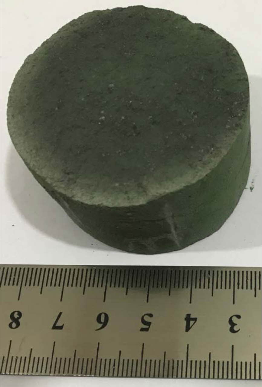
Fig. 7 shows the effect of oxidizing conditions on the structure of optimum sample. In this figure, the gray area indicates the oxidized layer. As can be seen, less than 20% of the sample is oxidized and the rest remained intact, indicating good oxidation resistance of the sample. By the way, it is worthy to note that, silicon is present as an antioxidant in this compound, which improves the oxidation resistance of graphite due to its greater reactivity with oxygen according to the thermodynamic data presented in Table 11.
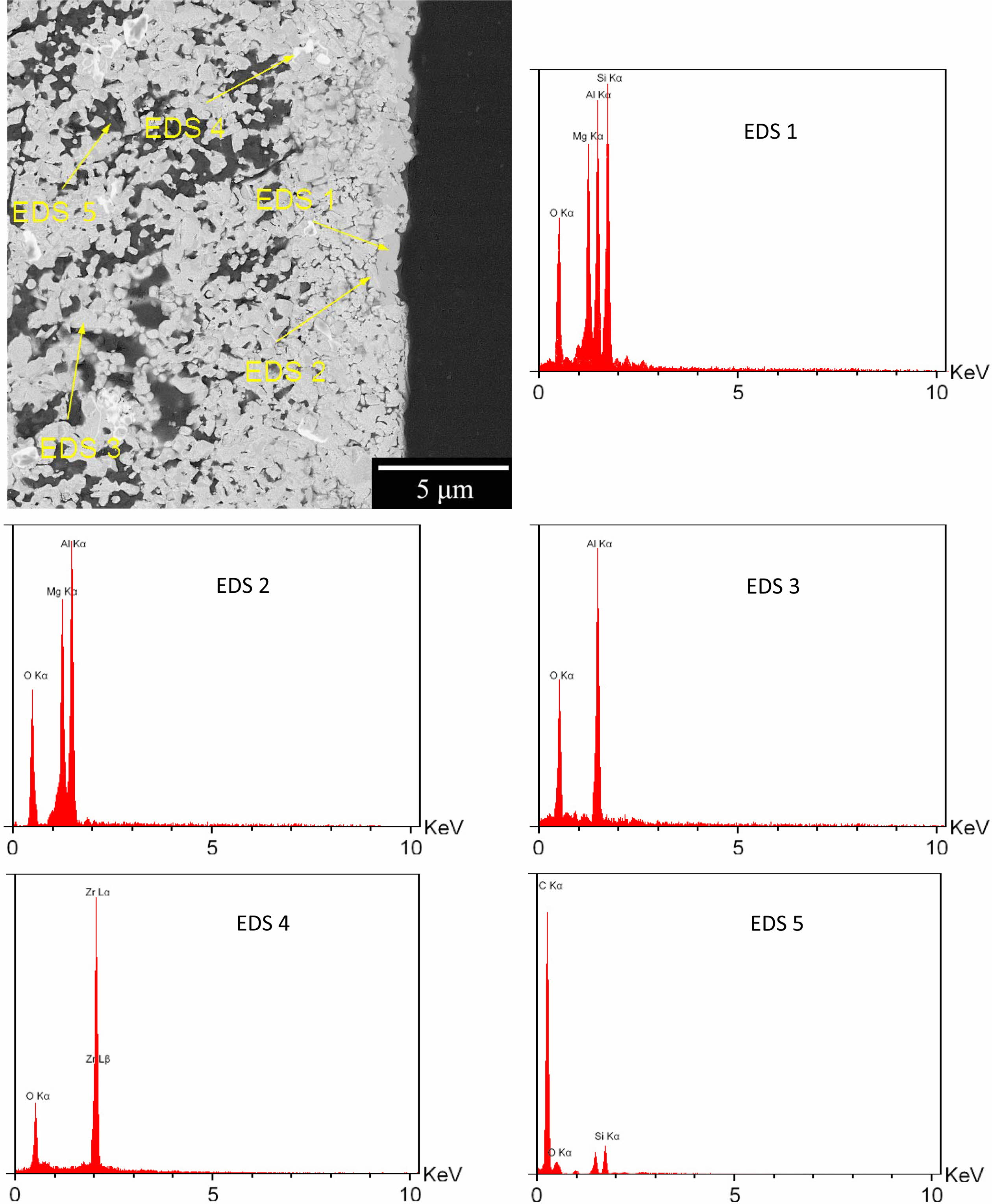
The reaction between oxygen and silicon / silicon car- bide, is thermodynamically more preferable than oxygen and graphite, which contributes to the refractory oxidation resistance. The backscattered (BSE mode) SEM image of cross-section of the oxidized sample is also shown in Fig. 8.
The atomic number sensitivity of BSE mode can be exploited to distinguish the particles [40]. In Fig. 8, the brighter particles represent zirconia (EDX 4) and the darker particles are graphite (EDX 5), but alumina, magnesia and silica are not discernible. As can be seen, no graphite is observed near the surface and the almost dense cordierite phase is formed (EDX 1), which is due to the interaction of cristobalite at the surface and MgAl2O4 spinel (EDX 2) [35].
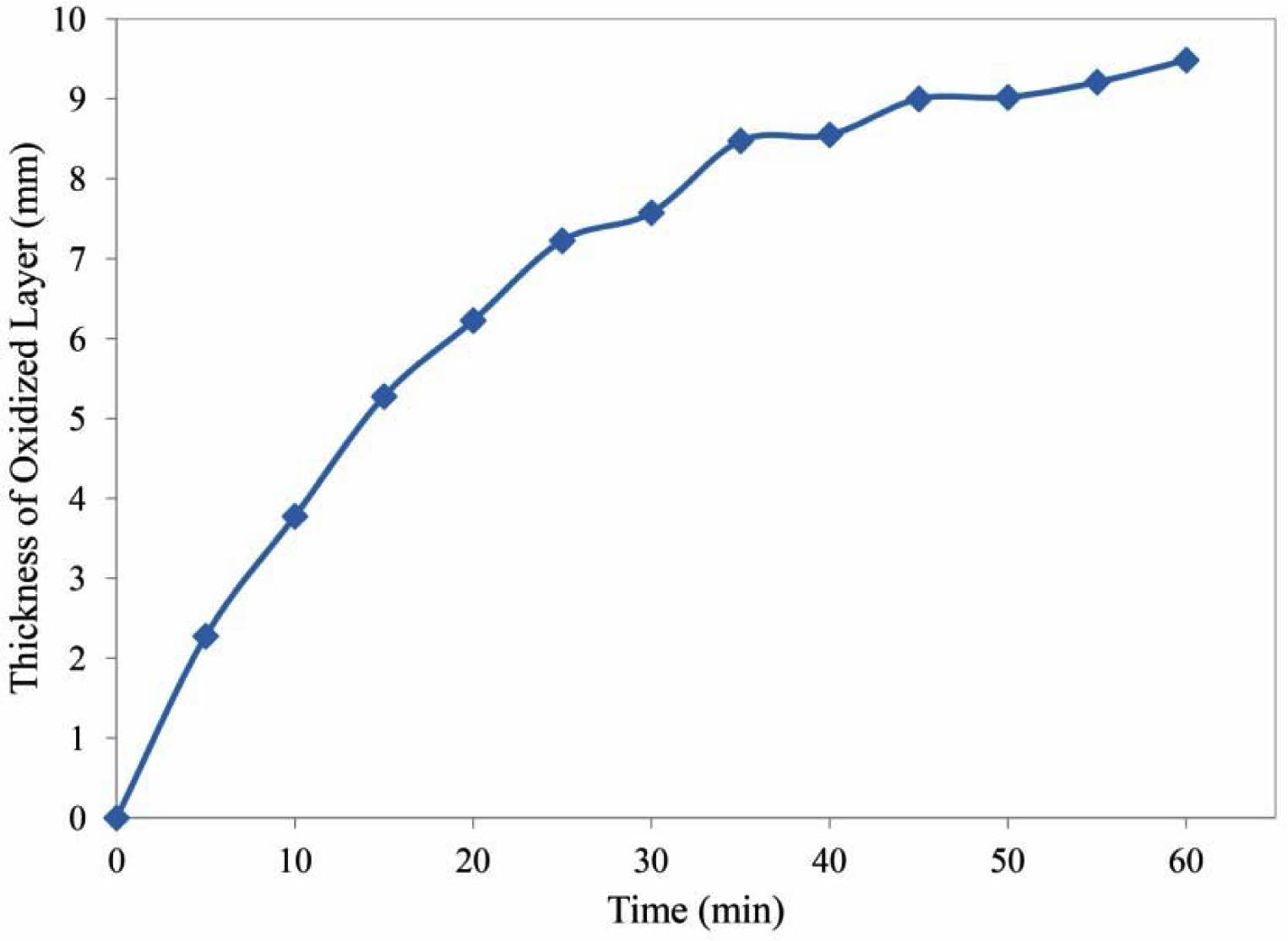
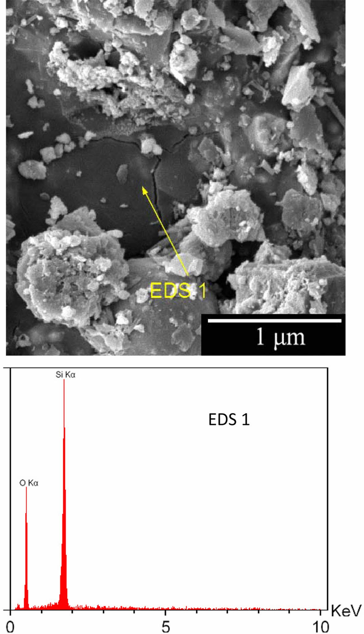
Fig. 9 shows the effect of time on the thickness of the oxidized layer. As can be seen, the oxidation rate decreases with time. The oxidation rate was initially high due to the access of oxygen to the graphite. Therefore, the rate of chemical reaction on the surface determines the rate of oxidation. Subsequently, graphite oxidation occurs through the oxygen diffusion through the porosities [41]. Subsequently, graphite oxidation occurs through the oxygen diffusion through the porosities which has lower rate than first step. In addition, formation of glass phase on the surface (Fig. 10) slows down the diffusion process. Oxidation of silicon results in the release of silicon monoxide (SiO(g)) from inside of the sample, resulting in the formation of a glass phase (SiO2) on the surface [42]. The glass layer prevents the penetration of oxygen and further oxidation.
|
Fig. 1 Normal probability plot of Predicted and actual value for AMZG refractory composites, (a) relative density, (b) modulus of rupture and (c) thickness of oxidized layer. |
|
Fig. 2 The effect of t-zirconia and MgO content (wt.%) on the relative density of AMZG refractory composites (a) fine graphite, (b) coarse graphite. |
|
Fig. 3 The effect of t-zirconia and MgO content (wt. %) on the modulus of rupture of AMZG refractory composites (a) fine graphite, (b) coarse graphite. |
|
Fig. 4 The effect of t-zirconia and MgO content (wt. %) on the oxidation of AMZG refractory composites (a) fine graphite, (b) coarse graphite. |
|
Fig. 5 X-ray diffraction pattern of the optimum specimen (tzirconia: 3.267 wt.%, MgO: 4.101 wt.% and fine-grained graphite) with corresponding Rietveld refined profile and the difference curve. The observed data are shown by the solid line (red), and the calculated data by the dotted Line (blue). The black Line Below is the Difference Profile. |
|
Fig. 6 STA thermogram for of the best specimen (t-zirconia: 3.267 wt.%, MgO: 4.101 wt.% and fine-grained graphite). |
|
Fig. 7 Oxidation behavior of the optimum specimen (t-zirconia: 3.267 wt.%, MgO: 4.101 wt.% and fine-grained graphite). |
|
Fig. 8 SEM image of cross-section of the optimum specimen oxidation in backscattered mode and corresponding EDS analysis. |
|
Fig. 9 The thickness of oxidized layer versus oxidation time at 900 oC. |
|
Fig. 10 SEM image of the surface of the optimum specimen oxidation and corresponding EDS analysis. |
|
Table 3 Design of experiments by central composite design for AMZG refractory composite |
|
Table 5 ANOVA test for CCD in the case of modulus of rupture of AMZG refractory composite |

|
Table 6 ANOVA test for CCD in the case of oxidation thickness of AMZG refractory composite |

|
Table 7 Fit statistics summary for CCD in the case of AMZG refractory composite density |

|
Table 8 Fit statistics summary for CCD in the case of AMZG refractory composite density |

|
Table 9 Fit statistics summary for CCD in the case of AMZG refractory composite density |

The AMZG refractory composite is prepared and is successfully modeled by employing the central composite design method. The effect of t-zirconia content (0-5 wt.%), magnesia content (0-10 wt.%) and graphite particle size on the relative density, modulus of rupture and atmospheric oxidation resistance is investigated comprehensively. The optimum condition was achieved at t-zirconia of 3.268 wt.%, MgO of 4.104 wt.% where fine-grained graphite is used. The predicted values for the relative density (RD), MOR and thickness of oxidized layer are 72.929%, 116.158 MPa and 9.485 mm, re- spectively, which its desirability is about 89%. The discrepancy between the actual results and the predicted values is about 10%, which indicated the reliability of the model.
This research is supported by Shiraz University that are greatly acknowledged.
- 1. E.H. Kim, G.H. Jo, Y.K. Byeun, Y.G. Jung, and J.H. Lee, J. Ceram. Process. Res. 14[2] (2013) 265-268.
- 2. Q.J. Chen, W. Yan, N. Li, X.L. Lin, B.Q. Han, and Y.W. Wei, J. Ceram.Process. Res. 17[10] (2016) 1100-1105.
- 3. L. Zhao, and V. Sahajwalla, ISIJ international 43[1] (2003) 1-6.
-

- 4. R. Khanna, V. Sahajwalla, B. Rodgers, and F. McCarthy, Metall. Mater. Trans. B 37[4] (2006) 623-632.
-

- 5. M.H. Bagherabadi, R. Naghizadeh, H.R. Rezaie, and M.F. Vostakola, J. Ceram. Process. Res. 19[3] (2018) 218-223.
- 6. H. Gheisari, S. Ghasemi-Kahrizsangi, E. Karamian, and A. Nemati, J. Nanoanalysis 6[1] (2019) 1-20.
- 7. T. Zhu, Y. Li, and S. Sang, J. Alloys Comp. 783 (2019) 990-1000.-
-

- 8. A.V. Yagovtsev, N.V. Obabkov, and I.D. Kashcheev, Refract. Ind. Ceram. 54[5] (2014) 388-391.
-

- 9. W.A. Calvo, P. Pena, and A.G.T. Martinez, Ceram. Int. 45[1] (2019) 185-196.
-

- 10. S.P. Yu, M.C. Wang, and M.H. Hon, J. Ceram. Soc. Japan 108[1260] (2000) 721-727.
-

- 11. V. Muñoz, P. Pena, and A.G.T. Martínez, Ceram. Int. 40[7] (2014) 9133-9149.
-

- 12. V. Muñoz, S. Camelli, and A.G.T. Martinez, Ceram. Int. 43[5] (2017) 4562-4569.
-

- 13. M. Klewski, O. Lucyna, S. Michał, and A. Refractories, in Proceedings of the Unified International Technical Confer- ence on Refractories (UNITECR 2013), Jan. 2014, edited by Dana G. Goski, and Jeffrey D. Smith (John Wiley & Sons, Inc. Press) p.715-718.
-

- 14. S. Mukhopadhyay, A.K. Chattopadhyay, G.C. Das, and S. Maitra, Int. J. Appl. Ceram. Technol. 11[6] (2014) 1012-1019.
-

- 15. Z.A. Babakhanova, and M.K. Aripova, Refract. Ind. Ceram. 59[5] (2019) 454-458.
-

- 16. S.P. Yu, K.H. YANG, M.C. Wang, and M.H. Hon, J. Ceram. Soc. Japan 109[1271] (2001) 596-601.
-

- 17. S.P. Yu, K.H. YANG, M.C. Wang, and M.H. Hon, J. Ceram. Soc. Japan. 109[1273] (2001) 748-752.
-

- 18. A.I. Khuri, and S. Mukhopadhyay, Wiley Interdiscip. Rev.: Comput. Stat. 2[2] (2010) 128-149.
-

- 19. A. Srivastava, N.K. Debnath, V. Kumar, P.H. Kumar, and V.K. Singh, Ceram. Int. 42[8] (2016) 10116-10121.
-

- 20. A.V. Maldhure, and A.V. Wankhade, J. Asian Ceram. Soc. 5[3] (2017) 247-254.
-

- 21. C. Gómez-Rodríguez, D. Fernández-González, L.V. García-Quiñonez, G.A. Castillo-Rodríguez, J.A. Aguilar-Martínez, and L.F. Verdeja, Metals 9[12] (2019) 1297.
-

- 22. S.S. Mirzaee, E. Salahi, and A. Khanlarkhani, Micro Nano Let. 13[6] (2018) 853-856.
-

- 23. H.S. Hammood, A.S. Mahmood, and S.S. Irhayyim, Period. Eng. Nat. Sci. 7[3] (2019) 1318-1328.
-

- 24. J.M. Mendoza-Duarte, R. Martínez-Sánchez, C. Carreño-Gallardo, and I. Estrada-Guel, Microsc. Microanal. 19[S2] (2013) 1568-1569.
-

- 25. Y. Mahyoedin, J. Sahari, A. Mukhtar, and N. Mohammad, in MATEC Web of Conferences (Vol. 248, p. 01007) (2018) EDP Sciences.
-

- 26. E.Y. Sako, M.A.L. Braulio, E. Zinngrebe, S.R. Van der Laan, and V.C. Pandolfelli, Ceram. Int. 38[3] (2012) 2243-2251.
-

- 27. J.N. Panda, J. Bijwe, and R.K. Pandey, Comp. B: Eng. 182 (2020) 107641.
-

- 28. N. Hansen, Scripta Materialia 51[8] (2004) 801-806.
-

- 29. I. Ganesh, Inter. Mater. Rev. 58[2] (2013) 63-112.
-

- 30. E.H. Sun, Y.H. Choa, T. Sekino, and K. Niihara, J. Ceram. Process. Res. 1[1] (2000) 9-11.
- 31. S.K. Mohan, and R. Sarkar, Ceram. Int. 42[8] (2016) 10355-10365.
-

- 32. E.F. Chaika, I.G. Maryasev, and A.A. Platonov, Refract. Ind. Ceram. 57[5] (2017) 449-461.
-

- 33. A. Yamaguchi, S. Zhang, and J. Yu, J. American Ceram. Soc. 79[9] (1996) 2509-2511.
-

- 34. E.L. Courtright, J.T. Prater, C.H. Henager, and E.N. Greenwell, BATTELLE PACIFIC NORTHWEST LABS RICHLAND WA (1991).
- 35. M.K. Naskar, and M. Chatterjee, J. Eur. Ceram. Soc. 24[13] (2004) 3499-3508.
-

- 36. S. Sembiring, W. Simanjuntak, R. Situmeang, A. Riyanto, and P. Karo-Karo, J. Asian Ceram. Soc. 5[2] (2017) 186-192.
-

- 37. L. Musante, V. Munoz, M.H. Labadie, and A.G.T. Martinez, Ceram. Int. 37[5] (2011) 1473-1483.
-

- 38. E.F. Krivoshapkina, P.V. Krivoshapkin, and A.A. Vedyagin, J. Adv. Ceram. 6[1] (2017) 11-19.
-

- 39. R. Bejjaoui, A. Benhammou, L. Nibou, B. Tanouti, J.P. Bonnet, A. Yaacoubi, and A. Ammar, Appl. Clay Sci. 49[3] (2010) 336-340.
-

- 40. T. Kowoll, E. Müller, S. Fritsch-Decker, S. Hettler, H. Störmer, C. Weiss, and D. Gerthsen, Scanning 2017 (2017) 1-12.
-

- 41. B. Hashemi, M.A. Faghihi-Sani, and Z.A. Nemati, Scientia Iranica 12[3] (2005) 274-279.
- 42. N.J. Shaw and A.H. Heuer, Acta Metallurgica 31[1] (1983) 55-59.
-

 This Article
-
2022; 23(2): 188-198
Published on Apr 30, 2022
- 10.36410/jcpr.2022.23.2.188
- Received on Oct 3, 2021
- Revised on Nov 10, 2021
- Accepted on Nov 27, 2021
 Services
- Abstract
introduction
experimental procedure
results and discussion
conclusion
- Acknowledgements
- References
- Full Text PDF
Shared
 Correspondence to
- Mohammad Hossein Paydar
-
Department of Materials Science and Engineering, School of Engineering, Shiraz University, Shiraz, Iran
Tel : +98-71-32307293 Fax: +98-7132307293 - E-mail: paaydar@shirazu.ac.ir



 Copyright 2019 International Orgranization for Ceramic Processing. All rights reserved.