- Investigation of urea selective catalytic reduction system with catalyst coated ceramic monolith
Devakaran Karaiellapalayam Palanisamya,* and Arunshankar Jayabalanb
aDepartment of Automobile Engineering, PSG College of Technology, Coimbatore
bDepartment of Instrumentation and Control Systems Engineering, PSG College of Technology, CoimbatoreThis article is an open access article distributed under the terms of the Creative Commons Attribution Non-Commercial License (http://creativecommons.org/licenses/by-nc/4.0) which permits unrestricted non-commercial use, distribution, and reproduction in any medium, provided the original work is properly cited.
The selective catalytic reduction (SCR) and fast-SCR retrofit systems effectively control the nitrogen oxides (NOx) emission for the diesel engine exhaust, using adblue solution and catalyst. The performance characteristic of retrofit system with efficient catalyst and optimum flow channel design, without affecting the engine performance is still a challenging factor. The experimental work is done on a stationary diesel engine test bench coupled to the retrofit system in its exhaust, at steady-state condition. A pair of ceramic monolith coated with cerium oxide (CeO2) and zeolite (ZSM-5) catalysts are used for pre-oxidation and SCR chambers respectively. The catalysts are characterized by XRD method and dip coated over the ceramic monolith. The static mixer blade inside the middle retrofit pipe is used for homogenization and complete evaporation of adblue solution. The influences of NOx conversion efficiency of retrofit systems are investigated with the ZSM-5 catalyst and later combined with CeO2 catalyst. From the experimental results, it is observed that the fast-SCR retrofit system with static mixer blade has a better NOx conversion efficiency, with marginal decrease in engine brake thermal efficiency than the other retrofit systems at maximum brake power. The increase in brake specific fuel consumption (BSFC) of the retrofit system causes the engine brake thermal efficiency to decrease marginally with increase in brake power
Keywords: Adblue, Ceramic monolith, CeO2, Fast-SCR and ZSM-5
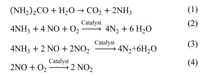
The major pollutants of the diesel engine exhausts are NOx and particulate matter (PM) in a lean-burn combustion environment [1, 2]. The development of retrofit technologies such as lean NOx catalyst (LNC), lean NOx trap (LNT), common rail direct injection (CRDI) and exhaust gas recirculation (EGR) reduces the NOx emissions, but the efficiency of diesel engine is affected [3]. The SCR retrofit technology is considered to be effective after treatment method, to regulate the NOx emissions for stationary and mobile diesel engines [4]. The emerging SCR technology involves a very precise quantity of adblue injected into the upstream of the SCR catalytic chamber [5]. In this process, the reactant ammonia (NH3) is produced by injecting an adblue through hydrolysis reaction as given in equation (1). The ammonia then reacts with NOx over the SCR catalyst either as standard SCR reaction or fast-SCR reaction given in equation (2) and equation (3) respectively. The pre-oxidation catalyst promotes the oxidation reaction as given in equation (4) which initiates the fast-SCR reaction.
The incomplete chemical conversion of adblue forms an undesirable salt deposition at the bottom of the retrofit tailpipe which adversely affects the SCR catalyst activity [6]. The excess of adblue injection into the engine exhaust yields NH3 slip at the tailpipe [7]. The design of adblue injection parameters such as injector nozzle, injection position, injecting temperature and injecting quantity also determines the NOx con- version efficiency [8, 9].
The design of SCR retrofit system for the diesel engine is investigated with diesel oxidation catalyst (DOC), two SCR catalytic chambers and ammonia oxidation catalyst (AOC) and the effects of NOx reduction efficiency are measured at steady-state condition [10]. An integration of DOC, catalytic diesel particulate filter (CDPF) and SCR retrofit systems are designed and experimented to evaluate the effects on PM and NOx emissions as per stringent emission norms [11,12].
Research has also focused on the design of novel SCR catalysts such as V2O5/WO3/TiO2, Fe/Cu-zeolite, ZSM-5 and Mn-based catalyst. The operating temperature of V2O5/WO3/TiO2 catalyst is only between 260 oC to 450 oC but has difficulty in NH3 storage [13, 14]. The binary and ternary (V2O5/WO3/TiO2) catalyst samples are examined by structural analyses and later NOx reduction efficiency is determined at different loadings and various temperature ranges [15]. The Fe-zeolite catalyst is operated up to 600 oC but prone to stability problems at higher temperature in the presence of moisture [16]. The Cu-zeolite catalyst has higher NOx conversion efficiency only between 200 oC to 400 oC but its durability is inadequate [17]. Mn-based catalyst has better performance but the efficiency is affected by its calcination temperature and O2 concentration in the reaction medium [18]. The CeO2 catalyst is a promising material for fast oxygen sensors at high temperature, because of its chemical stability and high diffusion coefficient of oxygen vacancies [19]. The different types of Zeolite with various Si:Al ratio are used as SCR catalyst for NOx reduction [20].
A ceramic monolith substrate with parallel flow channels of either square or triangular cells coated with catalytic material is extensively used for automotive and stationary SCR control reactors [21]. The internal flow distribution of gases in the retrofit system has a greater effect on NOx conversion efficiency. To enhance the performance, different types of mixers are designed and investigated for the SCR retrofit system [22]. A novel static mixer blade inside the retrofit system im- proved the uniform mixing of gases, which has better NOx conversion efficiency than commercially available mixer blade [23]. An improved NOx conversion rate is obtained with combination of two static mixer blades as compared with single static mixer blade in the retrofit system [24].
In the literature, optimizing factors such as adblue injection strategy, catalyst loading and static mixer blade are investigated separately at different experimental conditions, for enhancing the NOx conversion efficiency of diesel engine retrofit system. It is observed that there are still more chances for improving the performance characteristics of the retrofit system, without affecting the engine performance. The main contribution of this experimental work is the improvement in NOx conversion efficiency of diesel engine retrofit system, with the combined effect of pre-oxidation and SCR catalysts coated over ceramic monolith.
Catalyst selection
The cerium oxide (CeO2) and zeolite (ZSM-5) catalysts are selected for the pre-oxidation and SCR chambers respectively. The catalyst CeO2 can become non-stoichiometric in oxygen content depending on its ambient partial pressure of oxygen. In association with other catalysts, CeO2 is economical and promotes oxidation reaction to convert harmful emission to harmless [25]. The diesel engine exhaust contains 90% NO and 10% NO2 and by usage of CeO2 as pre-oxidation catalyst, it equalizes the concentration NOx into 50% NO and 50% NO2 which enhances the fast-SCR reaction [26].
The ZSM-5 is the most active catalyst at low and high temperatures for ammonia SCR reaction. It provides higher thermal stability to exhaust gas temperature and also has better NOx conversion efficiency when compared to other catalysts [27].
Catalyst characterization
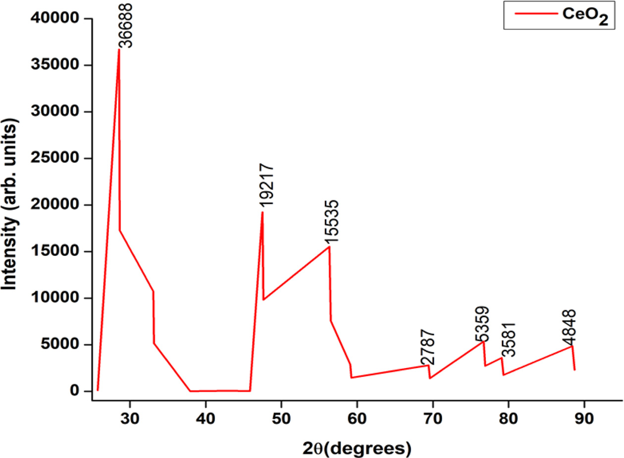
The standard procedure is adopted for catalyst characterization as given in [28]. The crystallinity and structure of catalysts are analyzed by X-ray diffraction (XRD) technique using Cu Kα radiation (45 kV, 30 mA). The scanning is operated in the 2θ range of 5o to 90o with a scanning speed 4.02 deg/min. The XRD pattern of CeO2 used for pre-oxidation catalyst is shown in the Fig. 1. The diffraction peaks at 2θ = [28.5, 47.5, 56.3, 69.4, 76.7, 88.7] are observed and these peaks attribute to the cubic structure of CeO2.
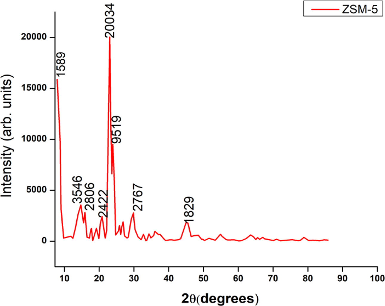
The standard procedure is adopted for SCR catalyst characterization as given in [29, 30]. The XRD pattern of ZSM-5 with Si:Al ratio of 50:1 is shown in the Fig. 2. The diffraction peaks are observed at 2θ = [7.9, 14.7, 15.8, 20.8, 23.04, 23.8, 24.3, 29.8, 44.9] and these attributes to the combination of decasodium dihydro- gendodecatungstate 27-hydrate substructure and tungsten oxide which are anorthic and monoclinic in crystal structure respectively.
Catalyst coating techniques
Washcoat preparation
The standard procedure is followed for wash coating over the ceramic monolith as given in [31, 32]. The first step involves the selection of appropriate volumes of ceramic monolith for pre-oxidation and SCR chambers. Initially, the weight of the ceramic monolith is measured. 100mL of distilled water is added and allowed to stir using a magnetic stirrer. Then 10 gm wt% of Al2O3 is added and allowed to stir well for a few minutes. Subsequently, glacial acetic acid (CH3COOH) is added gradually and stirred well. The above procedure is repeated until pH of 2-3 is obtained, after which the ceramic monolith is dipped into the slurry for a few seconds. After the monolith pore is cleared using a blower and dried in the oven for few minutes and later cooled to room temperature. Finally, the weight gained over ceramic monolith is measured and the above procedure is repeated until the required amount of Al2O3 gets coated over the ceramic.
The initial weight of the monolith is 18.1428 gm. The weight gained by the ceramic monolith after tenth immersion is 4.2530 gm. Then the washcoat procedure is repeated for other volume of ceramic monolith.
SCR and pre-oxidation catalyst incorporation
After wash coating, the standard procedure given in [33, 34] is followed during dip coating of ZSM-5 and CeO2 catalyst for SCR and pre-oxidation chamber respectively. Initially, the ceramic monoliths are dipped inside the respective catalyst solutions and then stirred using an ultrasonic bath. The water is removed by an air blower inside the ceramic monolith. Then the monoliths are placed inside a furnace at 100 oC for about 15 min to dry the water and cooled to room temperature. Finally, the above procedure is repeated until the required amount of catalyst gets coated over the substrate. The weights gained by the monoliths after fifteenth immersion are 5.3459 gm and 4.5824 gm for SCR and pre-oxidation catalyst respectively.
|
Fig. 1 XRD pattern of CeO2 catalyst. |
|
Fig. 2 XRD pattern of ZSM-5 catalyst. |
Experimental setup
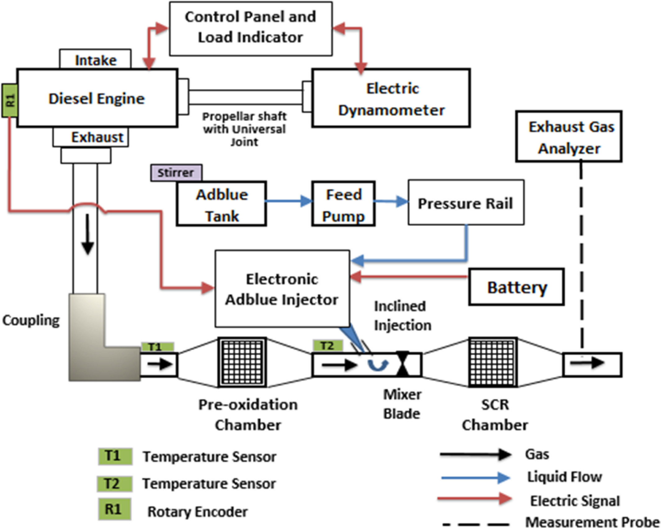
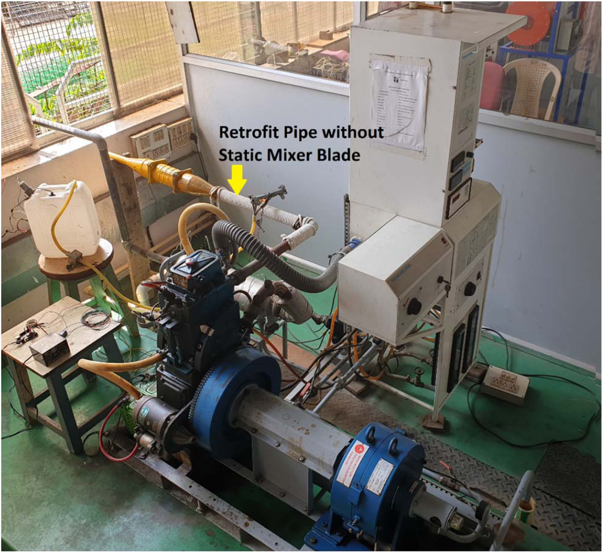
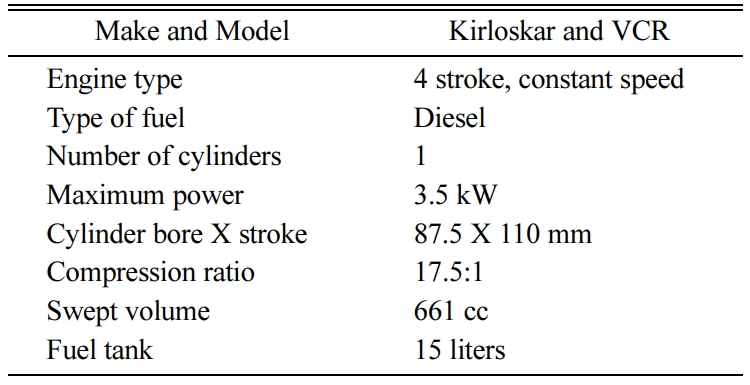
The schematic representation and picture of the engine test bench used for the experimental work are shown in Figs. 3-4. The test bench comprises a stationary diesel engine, with its specifications given in Table 1. The diesel engine is directly coupled to a dynamometer through a propeller shaft with a universal joint for controlling the engine load strategy. The specifications of dynamometer are given in Table 2.
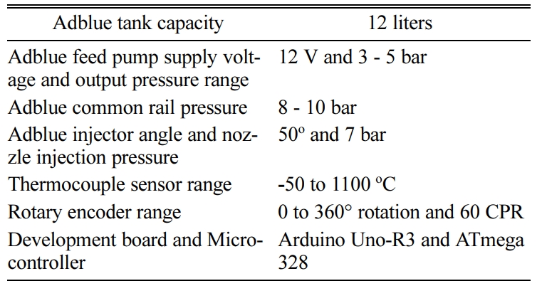
The volume of ceramic monolith depends on the engine displacement volume [35, 36]. A pair of ceramic monoliths are selected and coated with suitable catalyst for pre-oxidation and SCR chamber. The catalyst speci- fications are given in Table 3. The detailed specifications of the catalytic substrates are given in Table 3. An optimized static mixer blade comprising of eight blades, with the blades inclined at 45o are welded inside the middle retrofit pipe located after the adblue injection. The specifications of adblue associated components are given in Table 4. An exhaust gas analyzer is used to measure the NOx emission and their specifications are listed in Table 5.
Experimental Method
The engine test bench is started and warmed for 15 minutes. The intake system supplies sufficient air to run the engine. The direct torque control strategy is employed to the dynamometer, with the engine speed fixed at 1,500 rpm. The adblue is injected during the engine exhaust stroke period and a certain temperature of the exhaust gas. The rotary encoder measures the engine crank rotation for estimating period and the thermocouple measures the exhaust gas temperature for initiating adblue injection at 180 oC to 200 oC. The total fuel consumption at engine dynamometer scale and exhaust NOx emission are measured for no-load condition. Then the dynamometer load is increased to 3 kg which decreases the engine speed. To maintain the engine at constant speed, the total fuel consumption increases and their corresponding NOx emission is measured. This experimental procedure is repeated by changing the loads at equal intervals from no load to 12 kg in steps of 3 kg which represents 25% increase in engine brake power. The control of adblue injection quantity during the experiment is 50 mg/s. The efficiency of NOx conversion of retrofit systems, are investigated with SCR catalyst and later combined with pre-oxidation catalyst, with and without static mixture blade.
|
Fig. 3 Schematic of Diesel Engine Test Bench Setup |
|
Fig. 4 Picture of engine test bench setup with retrofit system |
Effect of brake power on brake thermal efficiency
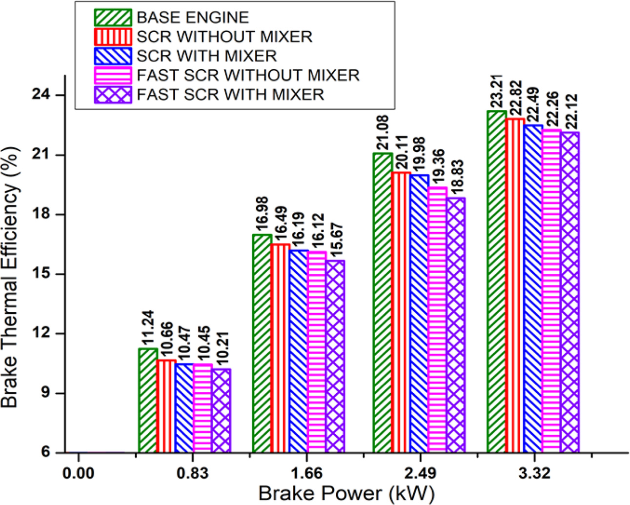
To study the effect of brake power on brake thermal efficiency, the brake power is increased from zero to full load at equal intervals of 25% as discussed in the experimental method. The results show that the brake thermal efficiency increases, with increase in brake power for the retrofit systems, as given in Fig. 5. The engine operating temperature increases with increase in brake power and hence, the brake thermal efficiency increases.
The brake thermal efficiency of the base engine is 23.21% at maximum brake power. The presence of catalytic filters restricts the exhaust gas, which reduces the engine brake thermal efficiency for SCR and fast-SCR systems without static mixture blade, by 0.39% and 0.95% respectively at maximum brake power. After the static mixture blade has been fitted inside the middle of the retrofit pipe, the restriction of exhaust gas further increases and hence, the reduction of engine brake thermal efficiency for SCR and fast-SCR retrofit systems improved to 0.72 % and 1.09 % respectively at maximum brake power.
The experimental results show the performance of the diesel engine with respect to brake thermal efficiency decreases marginally after the retrofit systems are coupled to the engine exhaust even at maximum brake power.
Effect of brake power on NOx reduction
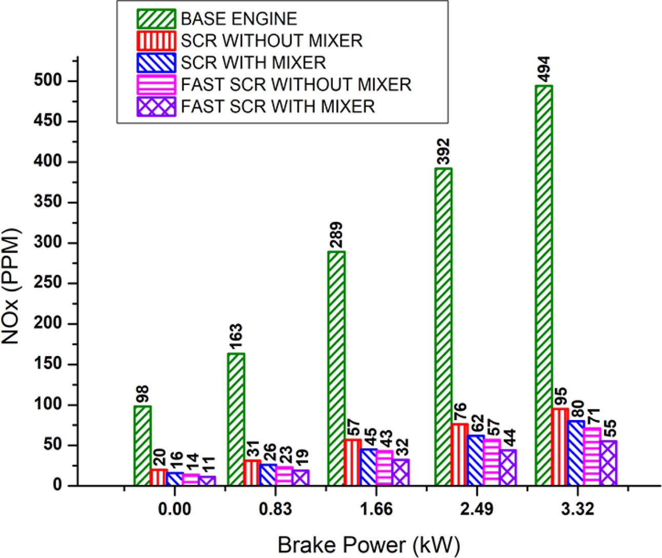
The effects of brake power on NOx reduction for the retrofit systems are shown in Fig. 6. From the results, it is observed that the engine cylinder peak temperature increases, with increase in brake power and hence the NOx increases.
The NOx of base engine without the retrofit system is 494 PPM at maximum brake power. When the adblue and the catalyst react with the exhaust gas, NOx conversion efficiencies are 81% and 86% for SCR and fast-SCR retrofit system without static mixer blade respectively at maximum brake power.
After the static mixer blade is fixed, uniform mixing of adblue solution with exhaust gas occurs and hence, the NOx conversion efficiency is further improved to 84% and 89% for SCR and fast-SCR retrofit systems respectively at maximum brake power. The highest NOx conversion efficiency of the retrofit system is due to the combined effect of pre-oxidation and SCR catalyst with mixer blade.
Effect of brake power on brake specific fuel consumption
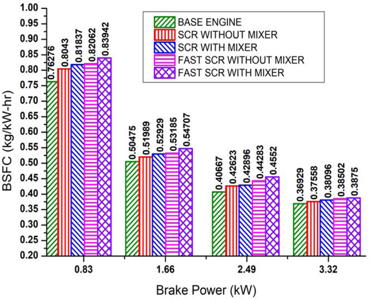
From the results, it is observed that brake power increases with increase in total consumption of fuel and hence, the BSFC decreases as shown in Fig. 7.
The BSFC of the base engine is 0.369 (kg/kW-hr) at maximum brake power. The presence of catalytic filters restricts the exhaust gas, which increases the BSFC for SCR and fast-SCR systems without static mixture blade, to 0.375 (kg/kW-hr) and 0.385 (kg/kW-hr) respectively at maximum brake power. After, the static mixture blade is fixed inside the retrofit pipe the restriction of exhaust gas further increases and hence, the BSFC for SCR and fast-SCR retrofit systems are further increased to 0.380 (kg/kW-hr) and 0.387 (kg/kW-hr) respectively at maximum brake power. The increase in BSFC causes the brake thermal efficiency of the engine to decrease with increase in brake power.
|
Fig. 5 Effect of brake power on brake thermal efficiency. |
|
Fig. 6 Effect of brake power on NOx reduction. |
|
Fig. 7 Effect of brake power on BSFC. |
In this work, control of NOx emission for the retrofit system and the performance of diesel are investigated. The retrofit system with SCR catalyst and then combined with pre-oxidation catalyst, with and without static mixture blade are examined. From the experimental results, the relative NOx conversion efficiency and reduction in engine brake thermal efficiency are improved for fast-SCR than the SCR retrofit system. The CeO2 catalyst inside the pre-oxidation chamber promotes the oxidation reaction and enhances NOx conversion rate with SCR catalyst. The static mixer blade inside the middle retrofit pipe improves the complete evaporation of adblue solution to react with SCR catalyst. The increase in BSFC of the retrofit system causes the engine brake thermal efficiency to decrease marginally with increase in brake power. The highest NOx conversion efficiency is obtained for fast-SCR retrofit system with static mixer blade, along with marginal decrease in engine brake thermal efficiency, as compared to other retrofit systems at maximum brake power.
NOx: Nitrogen Oxides
SCR: Selective Catalytic Reduction
PM: Particulate Matter
CeO2: Cerium Oxide
ZSM-5: Zeolite
LNC: Lean NOx Catalyst
LNT: Lean NOx Trap
CRDI: Common Rail Direct Injection
EGR: Exhaust Gas Recirculation
DOC: Diesel Oxidation Catalyst
AOC: Ammonia Oxidation Catalyst
BSFC: Brake Specific Fuel Consumption
- 1. B. Guan, R. Zhan, H. Lin, and Z. Huang, Appl. Therm. Eng. 66[1-2] (2014) 395-414.
-

- 2. X. Yuan, H. Liu, and Y. Gao, Emiss. Control Sci. Technol. 1[2] (2015) 121-133.
-

- 3. V. Praveena and M.L.J. Martin, J. Energy Inst. 91[5] (2017) 704-720.
-

- 4. M. Koebel, M. Elsener, and M. Kleemann, Catal. Today 59[3-4] (2000) 335-345.
-

- 5. H.T. Xu, Z.Q. Luo, N. Wang, Z.G. Qu, J. Chen, and L. An, Appl. Therm. Eng. 147 (2019) 198-204.
-

- 6. S. Sadashiva Prabhu, N.S. Nayak, N. Kapilan, and V. Hindasageri, Appl. Therm.Eng. 111 (2017) 1211-1231.
-

- 7. G. Liu, G.W. Bao, W. Zhang, D. Shen, Q. Wang, C. Li, and K. Luo, J. Energy Inst. 92[5] (2019) 1262-1269.
-

- 8. T.J. Wang, S.W. Baek, S.Y. Lee, D.H. Kang, and G.K. Yeo, AIChE J. 55[12] (2009) 3267-3276.
-

- 9. K. Bashirnezhad, M. Mehregan, and S.A. Kebriyaee, J. Energy Inst. 89[1] (2016) 115-120.
-

- 10. S. Bai, J. Han, M. Liu, S. Qin, G. Wang, and G. Li, Appl. Therm. Eng. 142 (2018) 421-432.
-

- 11. A. Ko, Y. Woo, J. Jang, Y. Jung, Y. Pyo, H. Jo, O. Lim, and Y.J. Lee, J. Ind. Eng. Chem. 80 (2019) 160-170.
-

- 12. Y. Zhang, D. Lou, P. Tan, and Z. Hu, Atmos. Environ. 177 (2018) 45-53.
-

- 13. C.P. Cho, Y.D. Pyo, J.Y. Jang, G.C. Kim, and Y.J. Shin, Appl. Therm. Eng. 110 (2017) 18-24.
-

- 14. B.P. Ayo, R.L. Fonseca, and J.R.G. Velasco, Appl. Catal. 363[1-2] (2009) 73-80.
-

- 15. B.W. Lee, H. Cho, and D.W. Shin, J. Ceram. Process. Res. 8[3] (2007) 203-207.
- 16. Y. Shin, Y. Jung, C.P. Cho, Y.D. Pyo, J. Jang, G. Kim, and T.M. Kim, Chem. Eng. J. 381 (2020) 122751.
-

- 17. J. Ochonska, D. McClymont, P.J. Jodlowski, A. Knapik, B. Gil, W. Makowski, W. Lasocha, A. Kolodziej, S.T. Kolaczkowski, and J. Lojewskaa, Catal. Today 191[1] (2012) 6-11.
-

- 18. J. Tan, Y. Wei, Y. Sun, J. Liu, Z. Zhao, W. Song, J. Li, and X. Zhang, J. Ind. Eng. Chem. 63 (2018) 84-94.
-

- 19. G. Balakrishnana, C.M. Raghavan, C. Ghosh, R. Divakar, E. Mohandas, J.I. Songa, S.I. Baea, and T.G. Kim, Ceram. Int. 39[7] (2013) 8327-8333.
-

- 20. K. Kamasamudram, N.W. Currier, X. Chen, and A. Yezerets, Catal. Today. 151[3-4] (2010) 212-222.
-

- 21. J.L. Williams, Catal. Today. 69[1-4] (2001) 3-9.
-

- 22. C. Zhang, C. Sun, M. Wu, and K. Lu, J. Fuel. 237 (2019) 465-474.
-

- 23. Q. Wang, D. Zhang, J. Wang, and S. Li, Appl. Mech. Mater. 316-317 (2013) 1156-1161.
-

- 24. Y.S. Cho, S.W. Lee, W.C. ChoiI, and Y.B. Yoon, Int. J. of Automotive Technol. 15[5] (2014) 723-731.
-

- 25. J.S. Park, J.G. Yeo, S.C. Yang, and C.H. Cho, J. Ceram. Process. Res. 19[1] (2018) 20-24.
- 26. B.K. Yun and M.Y. Kim, Appl. Therm. Eng. 50[1] (2013) 152-158.
-

- 27. J. Shao, S. Cheng, Z. Li, and B. Huang, Catal. 10[3] (2020) 311.
-

- 28. Y. Liu, C. Song, G. Lv, C. Fan, and X. Li, Catal. 8[8] (2018) 306.
-

- 29. B. Ganemi, E. Bjornbom, B. Demirel, and J. Paul, Microporous and Mesoporous Mater. 38[2-3] (2000) 287-300.
-

- 30. Z. Liao, K. Zha, W. Sun, Z. Huang, H. Xu, and W. Shen, Catal. 10[12] (2020) 1377.
-

- 31. S.-S. Park, D.-H. Yoon, S.-H. You, W.-T. Bae, and D.-W. Shin, J. Ceram. Process. Res. 9[6] (2008) 591-595.
- 32. E. Srinivasa Rao and P. Manohar, J. Ceram. Process. Res. 17[5] (2016) 448-453.
- 33. R. Durairaj, N. Subramanyan, and D. Duraiswamy J. Ceram. Process. res. 20[6] (2019) 621-631.
-

- 34. B. Shin, T.W. Dung, and H. Lee, J. Ceram. Process. res. 15[2] (2014) 125-129.
- 35. B.P. Pundir, in “Engine Emissions: Fundamentals and Advances in Control” (Alpha Science International Ltd, 2017) p.141.
- 36. V. Ganesan, in “Internal Combustion Engines” (McGraw-Hill Education, 4th Edition, 2015) p.517.
 This Article
-
2021; 22(1): 79-85
Published on Feb 28, 2021
- 10.36410/jcpr.2021.22.1.79
- Received on Jul 24, 2020
- Revised on Dec 2, 2020
- Accepted on Dec 4, 2020
 Services
- Abstract
introduction
catalyst characteristics and coating method
experimental setup and method
results and discussion
conclusion
abbreviation
- References
- Full Text PDF
Shared
 Correspondence to
- Devakaran Karaiellapalayam Palanisamy
-
Department of Automobile Engineering, PSG College of Technology, Coimbatore
Tel : +91422 4344281 Fax: +91422 2573833 - E-mail: kpd.auto@psgtech.ac.in





 Copyright 2019 International Orgranization for Ceramic Processing. All rights reserved.