


- Radiation shielding, physico-mechanical properties, microstructure, and sintering ability relationships in reactive alumina ceramics
Arife Yurdakul*
Department of Metallurgical and Materials Engineering, Faculty of Engineering, Kütahya Dumlupınar University, Kütahya, Türkiye
This article is an open access article distributed under the terms of the Creative Commons Attribution Non-Commercial License (http://creativecommons.org/licenses/by-nc/4.0) which permits unrestricted non-commercial use, distribution, and reproduction in any medium, provided the original work is properly cited.
This study systematically explores, for the first time, the relationships among sintering behavior, physico-mechanical properties, microstructure, and radiation shielding of reactive alumina ceramics. High-purity reactive α-Al2O3 powder with bimodal particle size distribution was pressurelessly sintered at 1550–1600 °C for 1–3 h. Nearly full densification (≥ 99% theoretical density) was achieved at 1550 °C–3 h and above. XRD and SEM–EDX confirmed single-phase corundum (α-Al2O3) formation. Increasing sintering temperature and dwell time enhanced densification and grain coarsening. The highest hardness (18.37 ± 0.45 GPa) occurred at 1550 °C–1 h, while the best fracture toughness (4.19 ± 0.62 MPa·m1/2) and flexural strength (387 ± 37 MPa) were obtained at 1600 °C–3 h. Crack deflection, bridging, branching, and nanopore-related mechanisms contributed to toughness improvement. Color values (L ≈ 90–95, a ≈ 0–1.7, b ≈ 9–12, ΔE ≈ 0–3.8) showed high stability. The best γ-ray shielding was achieved at 1600 °C–3 h, with linear attenuation coefficients of 29.959 cm⁻¹ (0.662 MeV), 22.789 cm⁻¹ (1.173 MeV), and 21.351 cm⁻¹ (1.332 MeV). These results indicate that reactive α-Al2O3 ceramics can be readily densified, offering excellent mechanical performance and radiation attenuation for advanced shielding panels and blocks.
Keywords: Al2O3, Radiation shielding, Reactive alumina, Physico-mechanical properties, Solid-state sintering.
Alumina, also known as aluminum oxide (Al2O3), is among the most significant technical ceramics due to its properties, including high hardness, strength, corrosion resistance, thermal shock resistance, wear resistance, electrical insulation, biocompatibility, and low cost [1-7]. Alumina ceramics are used in a wide range of applications, from electrical and electronics to dental applications, thanks to these superior engineering properties [1-7].
Reactive alumina is a fully ground product produced by dry grinding α-Al2O3 powders with a calcined corundum crystal structure in high-energy ceramic ball mills, resulting in a primary crystal size of 20 to >90% smaller than 1 µm [8-10]. Reactive α-Al2O3 powders are generally classified into two main groups based on their particle size distribution (PSD) shape: monomodal and multimodal [8-10]. Monomodal reactive α-Al2O3 concentrates around a specific particle size and appears as a single peak on the PSD graph, while its multimodal form is characterized by having more than one peak [8-10]. Both monomodal and multimodal PSD reactive α-Al2O3 powders have been evaluated in different applications due to their low particle size and high surface area [11-19]. More specifically, reactive α-Al2O3 powders are used in the production of castable alumina-based refractories [11, 12], mullite insulating substrates [13-15], alumina-magnesia [16], alumina-spinel castables [17], alumina-LaPO4 processable bioceramic composites [18], and Ca7ZrAl6O18-alumina cementitious composites [19]. In addition, Tang et al. [20] investigated the properties of compacted bodies, specifically relative density (maximum attainable value is ≈85% @1500 °C) and linear shrinkage (≈11.5% @1500 °C), by sintering three different reactive alumina powders at temperatures between 1100 °C and 1500 °C for a holding time of 3 hours. To the author's knowledge, no study has examined the sintering behavior of reactive α-Al2O3 powder at temperatures above 1500 °C to achieve its theoretical density. Such a study would explain the relationship between the phase, microstructure, and physico-mechanical properties of the densified bodies. This topic remains of interest in the literature.
Radiation technology is widely used in various sectors such as nuclear reactors, medical imaging, radiotherapy, and nuclear medicine [21, 22]. The increasing use of radiation in various aspects of daily life, along with its harmful environmental and health effects, has made the development of effective radiation materials a matter of great importance [21, 22]. Shielding is one of the fundamental principles of radiation protection and plays a critical role in reducing radiation exposure [21, 22]. The selection of material for shielding is contingent upon the type and energy of the radiation [21, 22]. Inexpensive, easy-to-produce, lightweight materials that exhibit high thermal and mechanical properties are good candidates for radiation shielding [21, 22]. Ceramic materials have recently gained popularity for radiation shielding applications due to their desirable properties, including strong oxidation resistance, low thermal expansion, a low dielectric constant, high density, and high melting points [21, 22]. At this juncture, to examine radiation shielding properties, the focus has been directed toward Al2O3 powder itself [22, 23], polymer-ceramic composites [21, 24, 25], high-speed steel composites [26] that employ alumina as an auxiliary reinforcement material, ZrSiO4-Al2O3 composites [27], unsintered block-shaped pressed Al2O3/PbO mixtures [28], blocks developed from alumina industrial waste [29], and Gd2O3/Al2O3 ceramic composites [30]. Accordingly, aluminum oxide in powder form has been reported to be a suitable material for radiation shielding applications, improving the attenuation capabilities of composite structures in which it is incorporated [21-30]. However, to date, no study has been found in the literature that directly investigates the radiation shielding behavior of sintered reactive α-Al2O3 bulk ceramics as a function of sintering temperature and dwell-time variables.
The objective of this study is to investigate the initial powder properties (surface area, particle shape, particle size distribution, initial phase content, and chemical composition), sinterability (traditional solid-state sintering with controlled temperature and dwell-time increases), microstructure development (phase type, phase composition, pore content, grain size development, and average grain size statistics), physico-mechanical properties (density, color, Vickers hardness, indentation fracture toughness, and fracture strength), and radiation shielding performance (photon mass-attenuation calculations). The results of this study are therefore expected to lead to the development of a new generation of inexpensive, easily produced alumina-based ceramic radiation shielding materials with acceptable physical and mechanical properties.
Raw materials and characterization
The primary raw material utilized for the initial batch was commercial high-purity grade reactive alumina powder (Admat Co., India). A range of analytical techniques was used to characterize the reactive alumina powder’s particle size, surface area, chemical composition, crystallographic phases, and microstructural features. These techniques included laser diffraction (Malvern Mastersizer 3000), Brunauer-Emmett-Teller (BET) method (Quantachrome Instruments brand and Autosorb-1-C/TCD model), X-ray fluorescence spectroscopy (XRF, Panalytical/Axios MAX), X-ray diffraction (XRD, Rigaku MiniFlex 600), scanning electron microscopy (SEM, Nova Nano 650), and energy dispersive X-ray spectroscopy (EDX, EDAX Tridient). Fig. 1(a-d) illustrates the XRD pattern, SEM image, EDX spectrum, and particle size graph of reactive alumina powder. Furthermore, the results of the reactive alumina's XRF chemical analysis are exhibited in Table 1. The polyvinyl alcohol (PVA) (Zag Kimya Co.), stearic acid (Acros Organics Co.), and 2-propanol (Sigma-Aldrich Co.) were also incorporated into the batches as organic constituents.
Processing of sintered reactive alumina ceramics
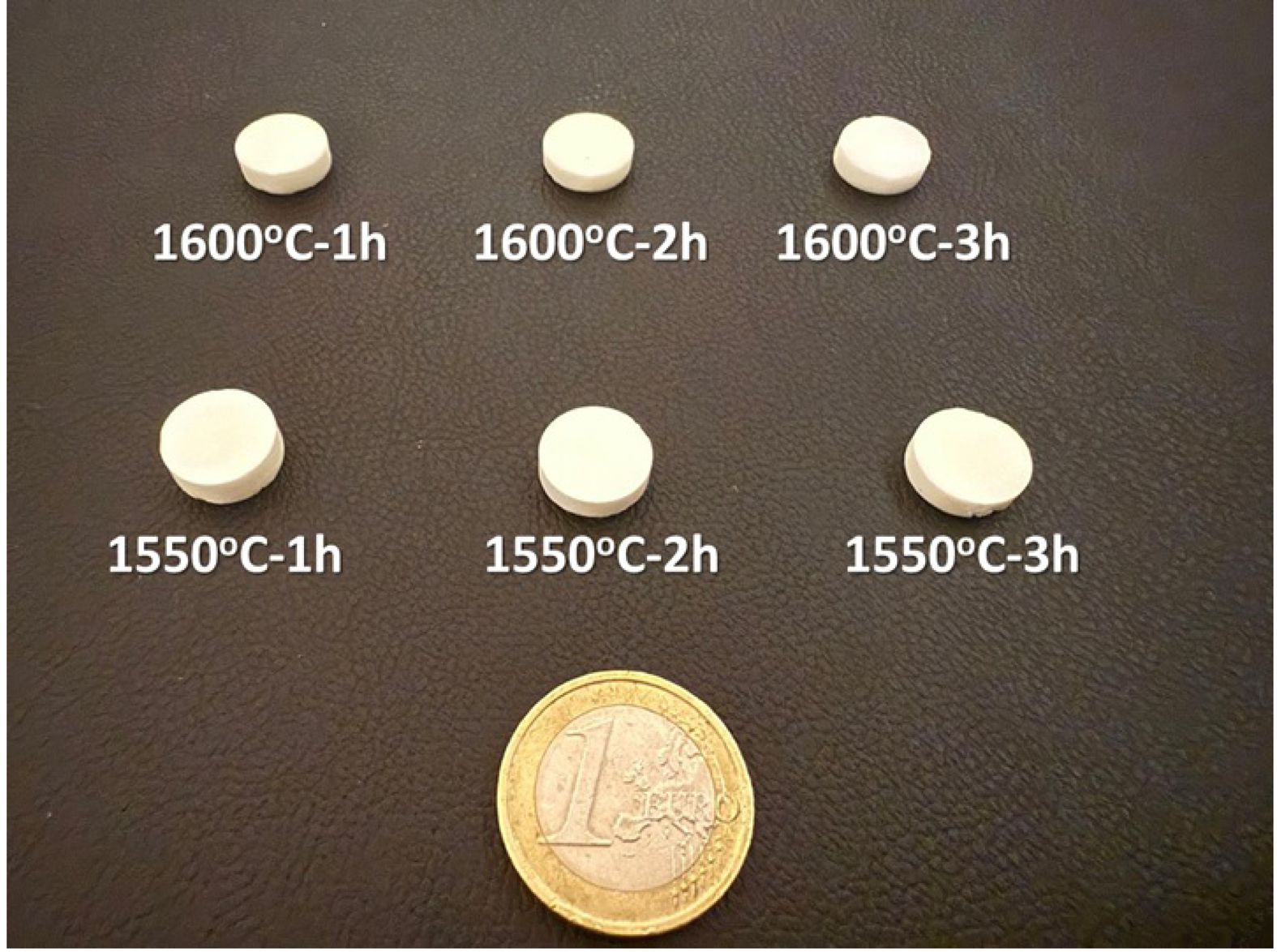
Batches of 500 g were prepared from the primary reactive alumina powder. The organics were also added to the batches at 2 wt.% PVA, 1.5 wt.% stearic acid, and 50 wt.% 2-propanol of 500 g total weight. The batches were wet-mixed by a bench-top planetary ball milling system (MTI Co., MSK-SFM-1 Model) at a rotational speed of 400 rpm/min for 24 h in a corundum (α-Al2O3) jar, including alumina balls with 3 mm, 5 mm, and 8 mm diameters. Following homogenization of all ingredients, the slurry was sieved through a 63 μm sieve. The resulting slurry alcohol was then subjected to a process of evaporation, which took place within an oven (Biuged Laboratory Instruments Co., BGD802 model) maintained at an exact temperature of 80 °C, for a period of 24 h. Then, the pellets were reduced to a powdery consistency via mechanical grinding, using an agate mortar and pestle. To apply indirect granulation, the homogenous powders, passed through a 45 μm sieve, were placed in pre-moisturized plastic bottles. The granules were pre-formed by a uniaxial hydraulic press at 45 MPa. Subsequently, the pre-formed pellets were compressed in the silicone molds using cold isostatic pressing (CIP, MSE Technology Ltd.) at 250 MPa and 1 min dwell-time to achieve high green density. The binder burn-out process was employed on the compacted disc-shaped bodies at 700 oC peak temperature for 2 h in ambient atmosphere by a heating rate of 1 oC/min, and 10 °C/min cooling rate from peak to room temperature (RT). Finally, organic-free samples were densified in an air atmosphere through conventional solid-state sintering at 1550 °C and 1600 °C maximum temperatures during 1 h, 2 h, and 3 h dwell-time by 5 °C/min heating rate, and 10 °C/min cooling rate to RT. Fig. 2 shows the visual images of sintered reactive alumina ceramics.
Characterization of sintered reactive alumina ceramics
Density measurements
Archimedes' principle technique was utilized to ascertain the bulk density values of sintered samples per the parameters set out in ASTM B 962-17 [31]. In this instance, the density values were calculated by accounting for the mean of five samples, taken from each S1-S6 specimen series in Table 2. For the current purpose, the dry weights (W1) of sintered specimens were initially measured using sensitive scales following moisture removal from the bodies for 1 h in the stove. The samples were boiled in 200 mL of distilled water at a temperature of 120 °C for 24 h. They were also suspended in Archimedes' balance to measure the suspended weight (W2). After this, the samples' surfaces were gently wiped and weighed to define the wet weight (W3). The bulk (ρBD) and % relative (RD) densities were thus derived from the following equations [32]. It is imperative to acknowledge that ρw (g.cm-3), as indicated in Eq. (1), signifies water's theoretical density (TD). Furthermore, the TD of α-Al2O3 was considered 3.95 in Eq. (2) [33].
Color analysis
The color analysis of the sintered samples was measured using a chroma meter (Konica Minolta CR-400) based on the CIE (International Commission on Illumination) L*, a*, and b* color scale technique [34]. Please note that five different samples from each S1-S6 series depicted in Table 2 were used during the color analysis test. Here, L*: lightness coordinate (L*=0 black and L*=100 white), a*: red-green axis (+a*: red and -a*: green) and b*: yellow-blue axis (+b*: yellow and -b*: blue). In addition, the a* and b* values range from -128 to +128. The CIE L*a*b* color scale is also designed to simplify the calculation of color differences between two points. The color deviation index (ΔE) is measured by taking the square root of the sum of the squares of the differences between the L*, a*, and b* values of two points according to Eq. (3) below.
In this context, a ΔE value of 1.5 or lower is typically regarded as imperceptible to the human eye, while a ΔE value of 3 or lower is widely accepted within most industries [35].
Mechanical tests
Tests were performed on the sintered bodies for Vickers hardness (HV, GPa) and indentation fracture toughness (KIc, MPa.m1/2). The 294 N load was utilized to derive the HV (GPa) and KIc (MPa.m1/2) values in the Vickers indentation instrument (Emco Test M1C 010). The low loads were also applied; however, no cracks were observed. In this experiment, twenty-five distinct indents were obtained for the mean values in every five different S1-S6 samples given in Table 2. The ASTM E384-10 standard was predicated on calculating hardness (H, GPa) values, as illustrated in Eq. (4) [36].
The P (N) and d (µm) terms in Eq. (4) correspond to the applied load and diagonal indentation. The KIc (MPa.m1/2) values were also derived from Niihara's formula (Eq. (5)), showing that Palmqvist cracks could be used in brittle materials with respect to radial-median type [37, 38].

SEM directly calculated the d (µm) and c (µm) values from the indent micrographs.The Young's modulus (E, GPa) of α-Al2O3 in Eq. (5) was 395 GPa [39].
The flexural strength (σ, MPa) of sintered reactive alumina bodies was calculated using a three-point bending test instrument (Instron Model 5581) at RT and the ASTM C1161-13 standard [40]. To perform this goal, samples were fabricated into rectangular prism-shaped bars with precise dimensions of 50±0.2 mm in length, 4±0.2 mm in width, and 3±0.2 mm in height. The load (N) was applied at a constant rate of 0.5 mm.min-1 to the bars during the test period until fracture occurred. The σ (MPa) values were obtained from Eq. 6 [40]. Herein, five test samples for each S1-S6 series, as shown in Table 2, were used to measure the mean and standard deviation data, reflecting variations in the sintering process.
Where P (N) corresponds to the failure load, L (mm) is the support span length, b (mm) is the specimen width, and h (mm) is the specimen height.
Radiation shielding analysis
To evaluate the radiation shielding performance of the prepared sample series, theoretical calculations were performed using the Phy-X/PSD platform, which is a user-friendly and widely recognized tool. For each sample, the chemical composition and density values were entered into the software, followed by selecting photon energies and radiation shielding parameters of interest. A broad photon energy range (0.015-15 MeV) was considered to ensure comprehensive insights into the radiation shielding characteristics. The linear attenuation coefficient (LAC) was emphasized among the evaluated parameters as a key indicator of photon-matter interactions. The Phy-X/PSD platform, which computes attenuation parameters by utilizing the NIST XCOM photon cross-section database and the Beer-Lambert exponential attenuation law, determined the LAC values based on Eq. (7) [41].

where I, Io, µ, and x are the intensity of the transmitted photon, intensity of the incident photon, linear attenuation coefficient (LAC), and thickness, respectively.
Within the scope of these calculations, the primary assumptions applied are: (i) samples are homogeneous and fully dense at the macroscopic scale, (ii) narrow-beam geometry is assumed (no photon build-up factor included), (iii) temperature-dependent electronic changes are neglected, and (iv) photon attenuation is governed by photoelectric absorption at low energies, Compton scattering at mid-energies, and pair production at high energies. The selected energy range of 0.015–15 MeV was intentionally broad to encompass the dominant photon interaction regimes relevant to practical shielding scenarios, including diagnostic X-rays (<0.1 MeV), industrial gamma emitters (0.662 MeV for Cs-137), and photon fields used in radiotherapy and nuclear facilities (>1 MeV).
XRD analysis
The XRD analysis of sintered reactive alumina bodies was conducted to detect the presence of crystalline phases through a Panalytical Empyrean high-resolution diffractometer. To get a high signal-to-noise ratio while acquiring data, the diffractometer was run by using Cu-Kα (1.5405 Å) radiation in a 2θ=5°-80° scanning range with 0.02 step-size and 1° min-1 scan speed under 40 kV voltage and 30 mA current.
Microstructural observations
To investigate microstructural evolution, sintered specimens were prepared via conventional methods (cutting, mounting, polishing, and thermal etching at 1100°C-5 min). The examination of the polished sample surfaces was conducted utilizing a field emission gun (FEG) scanning electron microscope (SEM) (Zeiss Supra 50 VP) and an EDX spectrometer (Oxford Instruments 7430). In SEM imaging, backscattered electrons (BSEs) were used to enhance the visibility of phases arising from atomic number (Z) contrast. The variable pressure (VP) mode was mainly operated to improve the SEM imaging quality without a conductive coating on the sample surfaces. The particle size distribution statistics of the phases observed in the microstructures were calculated using ImageJ software [42].
|
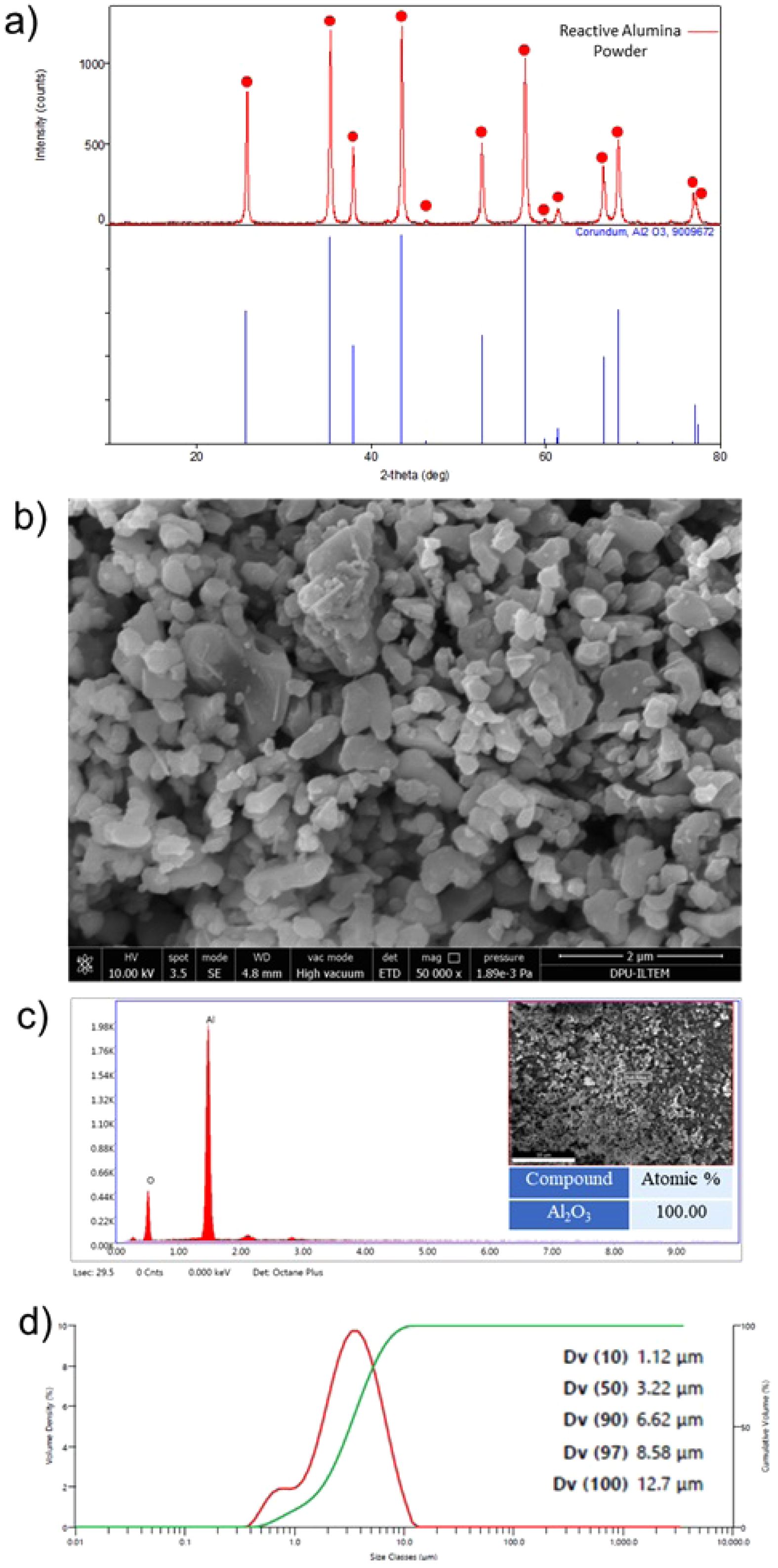
Fig. 1 Reactive alumina powder: a) XRD pattern, b) SEM image, c) EDX spectrum and semi-quantitative analysis result (the inset SEM image shows where the EDX analysis was taken from), and d) particle size distribution graph. |
|
Fig. 2 Images of the densified bodies produced after solid-state sintering of reactive alumina powder at 1550 °C and 1600 °C for 1 h, 2 h, and 3 h. |
|
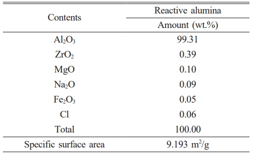
Table 1 The XRF chemical analysis and BET specific surface area results of the reactive alumina raw material. |
|
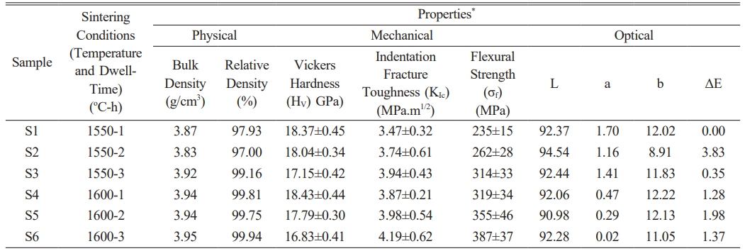
Table 2 Bulk density, relative density, Vickers hardness, indentation fracture toughness, flexural strength, L, a, b, and ΔE results of reactive alumina sintered samples. |
*Bulk density, Vickers hardness/indentation fracture toughness, flexural strength, and color analysis measurements were obtained from 5 different sintered samples in each S1-S6 specimen series |
Characterization of reactive alumina powder
Considering the XRD analysis result presented in Fig. 1(a), it was determined that all the diffraction peaks recorded from the reactive alumina powder belong to the corundum (α-Al2O3) phase, as indicated by the JCPDS card number 96-900-9672. In addition, examination of the XRF analysis given in Table 1 shows that the reactive alumina powder contains 99.31 wt.% Al2O3 in its elemental oxide composition. The remaining 0.69 wt.% of the composition consists of ZrO2 (0.39 wt.%), MgO (0.10 wt.%), Na2O (0.09 wt.%), Cl (0.06 wt.%), and Fe2O3 (0.05 wt.%) in that order. As illustrated in Fig. 1(b), the SEM image reveals that the reactive α-Al2O3 particles predominantly comprise submicron particles in the form of equiaxed plates with a particle size below 2 µm. Concurrently, when evaluating the EDX area analysis results recorded from a large region (35×35 µm²) containing reactive α-Al2O3 particles (Fig. 1(c)), only Al and O elements corresponding to a composition of 100 wt.% Al2O3 was detected in the spectrum. Furthermore, upon examining the particle size distribution (PSD) graph shown in Fig. 1(d), it was determined that the average PSD value (Dv(50)) of the reactive α-Al2O3 powder was 3.22 µm. In addition, the two peaks at different volume density values seen in the PSD graph indicate that the reactive α-Al2O3 powder has a bimodal PSD character. The specific surface area of reactive α-Al2O3 powder was determined to be 9.193 m2/g based on the BET analysis results (Table 1). It can be posited that the detailed powder characterization results obtained from the reactive alumina used in this study are consistent with analogous results reported in the existing literature [8-11, 13-18, 20]. Accordingly, the study on the production of reactive alumina for the refractory industry [8] ascertained that the reactive alumina is in the form of 100 wt.% α-Al2O3, with a Na2O content ranging from 0.250 to 0.325 wt.%, a specific surface area varying between 3.573 and 6.624 m2/g, and a multimodal PSD with a submicron particle size. Additionally, another study [11] demonstrating the effect of reactive alumina on the physico-mechanical properties of castable refractories reported that the reactive alumina contained 99.8 wt.% Al2O3 as the main oxide component, with impurities of 0.07 wt.% Na2O, 0.04 wt.% MgO, 0.03 wt.% CaO, 0.02 wt.% SiO2, and 0.01 wt.% B2O3. Also, in studies on mullite production using reactive alumina-kaolin/clay mixtures [13-15], it was noted that reactive alumina exhibited an average PSD of Dv (50)=0.7 µm and contained 99.85 wt.% Al2O3. In a study examining the effects of reactive alumina on the production of castables alumina-magnesia [16], the Dv (50) values of the two different reactive alumina used were found to be 2.51 µm and 2.87 µm. Similarly, one of the three reactive alumina used in the production of castables alumina-spinel was a monomodal PSD, while the other two exhibited a bimodal PSD [17]. In addition, the specific surface area values of these powders were reported to be 2.40 m2/g, 2.66 m2/g, and 4.32 m2/g [17]. Reactive alumina powder with a Dv (50) of 0.4 µm and a specific surface area of 8.9 m2/g, containing 99.8 wt.% Al2O3, was used in the production of reactive alumina-LiPO4 composites [18]. In studies conducted by Trubitsyn et al. [9, 10], chemical impurities in the composition, average PSD, and specific surface areas of reactive alumina powders of various grades manufactured by different producers were examined in detail and compared. Accordingly, the powders contain 0.03-0.05 wt.% SiO2, 0.03-0.1 wt.% Fe2O3, and 0.12-0.35 wt.% Na2O impurities, with Dv (50) values and specific surface areas ranging from 1.8-2.5 µm and 0.85-5.0 m2/g, respectively [9, 10]. In a study conducted by Tang et al. on the effect of powder characteristics on the sintering behavior of reactive alumina powders [20], three different powders with Dv (50) values ranging from 1.3 µm to 2.4 µm and specific surface areas between 2.7 m2/g and 4.3 m2/g were used. When the characterization results of the reactive α-Al2O3 powder used in this study (Fig. 1(a-d) and Table 1) were compared in detail with the properties of powders from different manufacturers [8-11, 13-18, 20], the reactive alumina used herein was found to have sufficient powder specifications to produce monolithic α-Al2O3 ceramics.
Phase, microstructure, and physico-mechanical analyses results of sintered reactive alumina ceramics
Table 2 shows the bulk and relative density values of the samples obtained by sintering reactive α-Al2O3 powder at 1550 °C and 1600 °C for 1, 2, or 3 hours.
Upon evaluating the results (Table 2), it was determined that the bulk density values of sintered reactive α-Al2O3 bodies increased as both the sintering temperature and holding time increased. In other words, bodies with nearly theoretical density were successfully produced from reactive α-Al2O3 powders using traditional pressureless solid-state sintering. To be more precise, the highest relative density value (99.94%) was achieved under sintering conditions of 1600 °C and 3 hours. At this point, it is evident that achieving high densification using reactive α-Al2O3 powders at 1600 °C for 3 hours is a repeatable process. It is also noteworthy that the relative density value at 1550 °C-3 h was recorded as 99.16%. This result indicates that fully dense corundum (α-Al2O3) ceramics can be produced from reactive alumina powder at lower sintering temperatures. Here, a driving force required for the densification of reactive α-Al2O3 particles was provided by increasing the sintering temperature and holding time. It is well-known that diffusion is the most effective mechanism for controlling the sintering process of fine-grained materials in a solid state at high temperatures. Diffusion generally occurs along grain boundaries. In the diffusion process, grain boundary diffusion and interfacial reaction are two fundamental processes that occur sequentially; therefore, the slower of these mechanisms dominates the sintering process. At this point, since the smaller PSD provides a shorter transport path, the interfacial reaction becomes important during the sintering process. In the sintering of pure alumina ceramics, when the PSD value is less than 3 µm, the interfacial reaction is the dominant mechanism [43]. Thus, elevating the sintering temperature and dwell time led to a reduction in the distance between grains, resulting in the elimination of pores at grain boundaries and triple-junction points through interfacial reactions along the grain boundaries. This situation resulted in the production of bulk sintered structures with RD ≥ 97.00% from reactive α-Al2O3 powder (Table 2). Additionally, a study on obtaining sintered structures using a limited number of reactive alumina powders in the literature [20] reported that only an RD value of around 85% could be achieved at 1500 °C for 3 hours. It was mentioned that the high surface area of reactive alumina and the presence of SiO2 as an impurity in its chemical composition had a positive effect on sintering [20]. Similarly, the high surface area of the reactive α-Al2O3 powder used in this study, as well as the presence of impurities such as ZrO2, MgO, Na2O, and Fe2O3 in its chemical composition, may have contributed to densification. This could have occurred by increasing diffusion and forming a temporary liquid phase at grain boundaries while inhibiting grain growth at any stage of sintering.
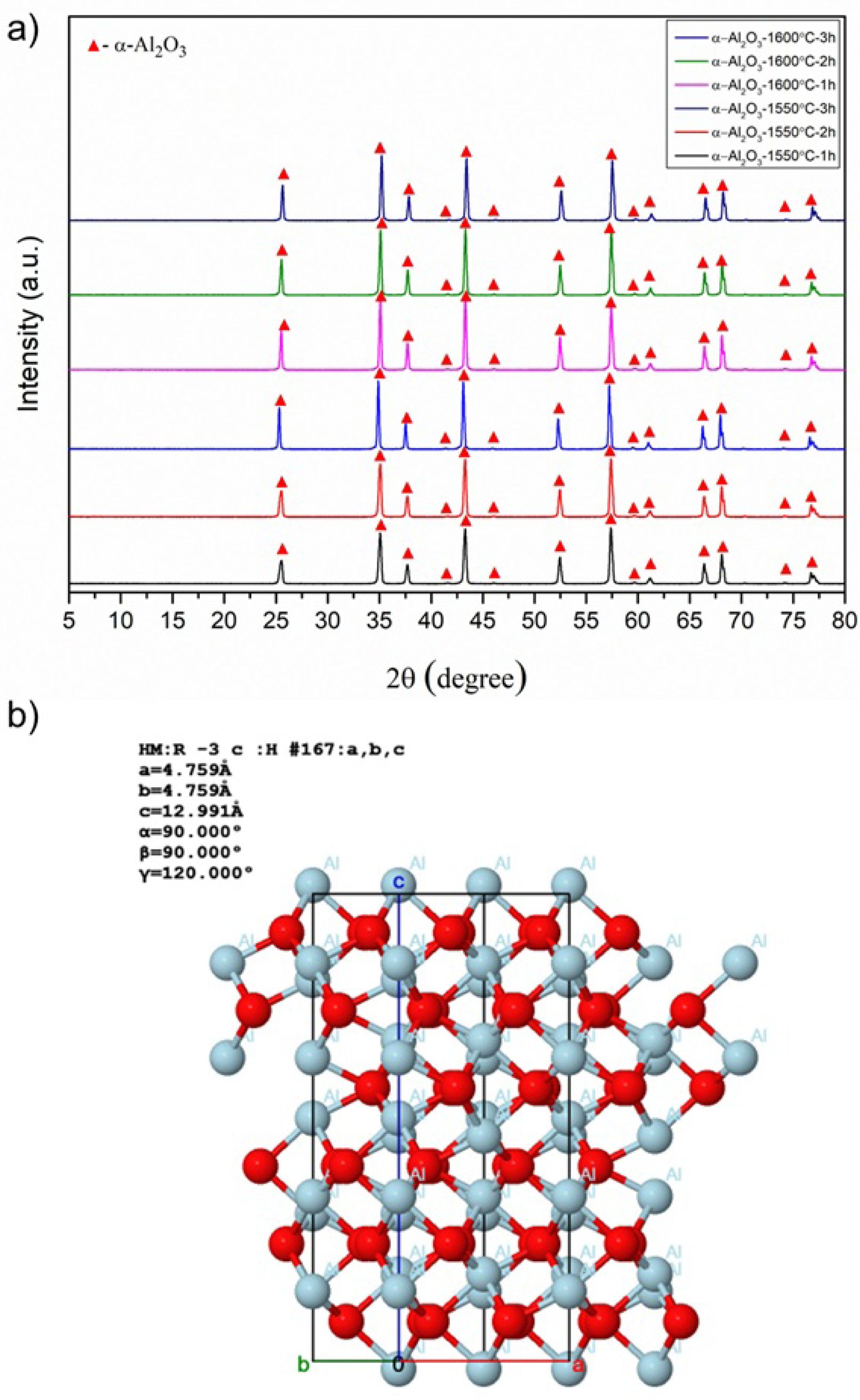
Fig. 3(a) presents comparative results of XRD phase analysis of bulk samples obtained by sintering of reactive α-Al2O3 powder at 1550 °C and 1600 °C for 1, 2, or 3 hours using the traditional solid-state sintering method.
Accordingly, the diffraction peaks in the XRD patterns of all samples with variable sintering temperatures and dwell time were determined to belong to the corundum (α-Al2O3) phase, as identified by JCPDS card number 98-008-5137. Corundum is the most thermodynamically stable phase of aluminum oxide. As shown in Fig. 3(b), the crystal structure consists essentially of a dense arrangement of Al3+ ions and oxygen ions occupying two-thirds of the octahedral sites within the hexagonal close-packed structure [44]. In addition, no new phase formation or transformation occurred with increasing sintering temperature and dwell time. Thus, it was concluded that the sintering process parameters used in this study were sufficient to produce bulk α-Al2O3 ceramics from reactive alumina powders.
Table 2 also shows the Vickers hardness (Hv) and indentation fracture toughness (Kıc) values of sintered reactive α-Al2O3 ceramic bodies. First, an evaluation of the Hv and Kıc results of sintered bodies revealed that Hv values decreased and Kıc values increased with higher sintering temperatures and longer durations. Here, the highest Hv value (18.37±0.45 GPa) was obtained in the S1-coded sample sintered at 1550 °C for 1 hour, while the maximum Kıc (4.19±0.62 MPa·m1/2) was observed in the S6-coded structure densified at 1600 °C for 3 hours. The Hv of the S6-coded body exhibiting the highest Kıc value was recorded as 16.83±0.41 GPa. This value is only 8.38% less than that of sample S1, which exhibited the highest Hv value. Here, the decrease in Hv values of sintered reactive α-Al2O3 structures can be explained by the Hall-Petch equation, which states that hardness decreases as grain size increases [44]. Furthermore, it is known that grain size increases along with bulk density as a result of the solid-state sintering process [43]. Thus, increasing the temperature and dwell time—both of which play a key role in densification—increases the density of reactive α-Al2O3 structures. This also causes the grains to grow, leading to a decrease in Hv values. In terms of indentation Kıc, normal grain growth during sintering increases Kıc values by allowing cracks to follow longer paths along grain boundaries, thereby reducing their energy [46]. The thermal stress generated during the cooling stage of sintering results in changes in the mechanical properties of the sintered specimens. During cooling, the internal stress formed in samples with larger grains creates microcracks that positively contribute to the material's fracture toughness [47]. Furthermore, after sintering, micro- and nano-sized pores within the grain boundaries and grains may have enhanced fracture toughness by dissipating the energy of the crack [48].
When examining the flexural strength (σ) values of the sintered reactive α-Al2O3 bodies given in Table 2, the σ values increased significantly with increases in both sintering temperature and holding time. More specifically, the σ value of the S1-coded sample sintered at 1550 °C for 1 hour was measured as 235±15 MPa, while the highest σ value of 387±37 MPa was recorded for the S6-coded sample sintered at 1600 °C for 3 hours. Here, the main reason for obtaining a high σ value can be attributed to the increase in the % RD density values of sintered reactive α-Al2O3 samples with the increasing sintering temperature and holding time [49]. Another reason is that at sintering temperatures above 1450 °C, it was reported that the flexural strength of sintered bodies containing bimodal alumina increases by dispersion strengthening due to the increased content of finer α-Al2O3 powder [50].
Upon reviewing numerous studies investigating the physico-mechanical properties (ρBD, % RD, Hv, Kıc and σ) of α-Al2O3 ceramics, traditional solid-state sintering, liquid-phase sintering, two-step sintering, microwave sintering, spark plasma sintering (SPS), flash sintering, cold sintering, and hot isostatic pressing (HIP) were firstly used to produce bodies close to the theoretical density (ρTDAl2O3) [51-58]. Secondly, studies were conducted using alumina powder sources with different crystallographic polymorph structures, where the purity, particle size, and synthesis method of these powders vary [59, 60]. Based on the results of these studies, which have been performed so far across an extensive range, sintered α-Al2O3 ceramics generally exhibited ≥95-99% of ρTD, Hv: ~12-20 GPa, Kıc: ~2.5-5.5 MPa.m1/2, and σ: ~250-450 MPa values [51-60]. To the author's knowledge, no direct study has been found in the literature on the detailed investigation of the mechanical properties of sintered bodies produced from reactive α-Al2O3 powder. Therefore, when the physico-mechanical properties of the sintered reactive α-Al2O3 structures presented in Table 2 are compared with other studies in the literature [51-60], it can be stated that the properties of the S6 structure sintered at 1600 °C for 3 h (99.94% of ρTD, Hv=16.83±0.41 GPa, Kıc=4.19±0.62 MPa·m1/2, and σ=387±37 MPa) are quite consistent with the values recorded to date.
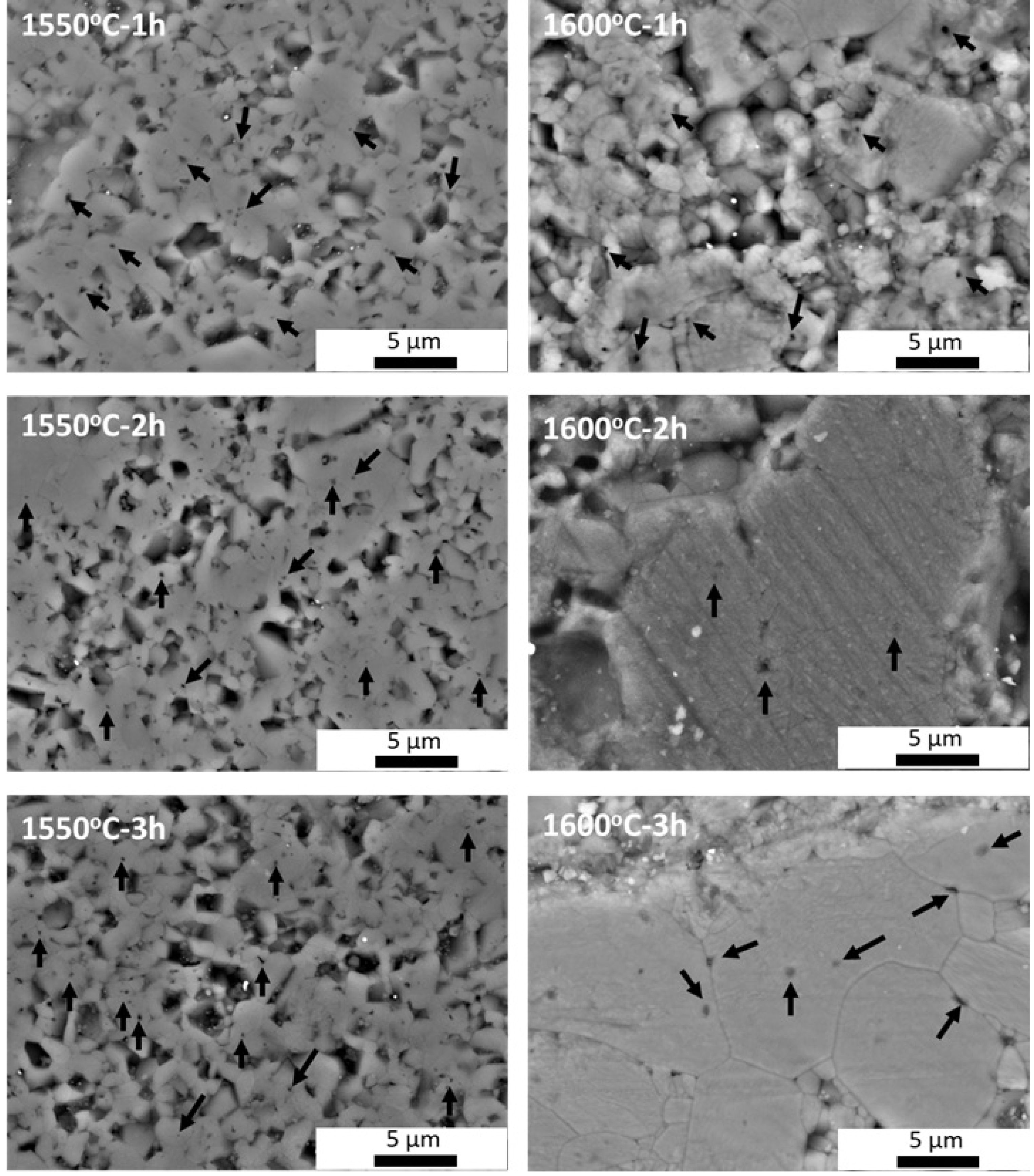
Within the scope of microstructural investigations, SEM images recorded from sintered reactive α-Al2O3 bodies depending on increasing sintering temperature and time, average grain size histograms of grains developing throughout the microstructure, and EDX chemical analysis results are presented in Fig. 4, Fig. 5, and Fig. 6, respectively.
Examining the SEM images in Fig. 4 reveals at first glance that the density of sintered reactive α-Al2O3 samples increases, and the pores in the structure decrease with increasing sintering temperature and time, resulting in a more compact structure. Upon closer analysis of the SEM images, it is evident that the interconnected pores within the grains or at the triple junctions along the grain boundaries (marked with black arrows in the images) decrease in size as sintering progresses. At the same time, similar to the microstructure development observed in the pressureless solid-state sintering of alumina without any sintering additives [61], the presence of nano-scale pores trapped within or at the boundaries of abnormal growth α-Al2O3 grains is directly observable in this study (SEM images at 1600 °C for 2 h and 3 h). It has been reported that the normal and abnormal grain growth observed during the solid-state sintering process of alumina ceramics is primarily related to the sintering temperature and dwell time [61]. It has also been stated that such grain growth can be prevented by using commercially available powders with a purity of 99.99% [61]. For this reason, impurities in the chemical composition of reactive α-Al2O3 powder (Table 1) may have played an effective role in the grain growth observed in sintered structures at 1600 °C for 2 h and 3 h. Furthermore, it is noteworthy that the fine particles actually form the skeletal structure of the coarse particles. This effect can be seen more clearly in microstructures sintered at 1600 °C for 2 h and 3 h. In this case, an increase in the sintering time led to a shift in the surface energies of the bimodal α-Al2O3 particles, causing them to move toward the center of particles with small curvature radii at large grain boundaries [50]. Thus, the large grains grew even larger due to the driving force, and the small grains observed in the sintered SEM microstructures at 1550 °C-1 h, 2 h, and 3 h disappeared.
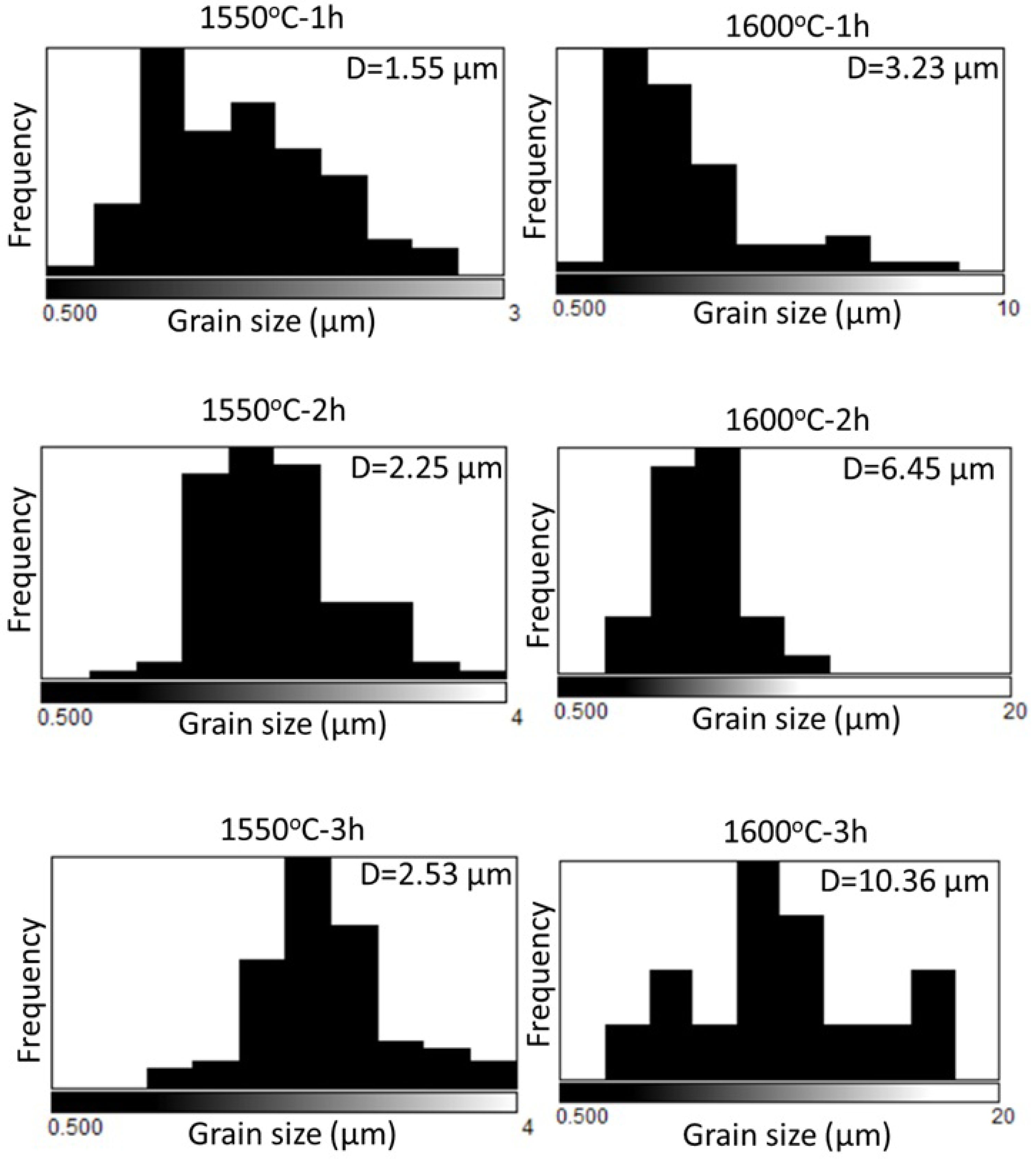
This prediction is supported by the average grain size distribution histograms of reactive α-Al2O3 grains, observed in the SEM microstructures of the sintered bodies in Fig. 4, as a function of sintering temperature and dwell time in Fig. 5. Accordingly, when examining the histograms in Fig. 5, the average grains sizes (D) of α-Al2O3 grains after 1 h, 2 h, and 3 h sintering at 1550 °C were respectively determined to be 1.55 µm, 2.25 µm, and 2.53 µm, while the average grain sizes at the same holding times at 1600 °C were found to be 3.23 µm, 6.45 µm, and 10.36 µm. Thus, based on the SEM images presented in Fig. 4, the observation that densification increases with increasing sintering temperature and time, accompanied by the growth of reactive α-Al2O3 particles, has also been confirmed numerically. At this point, SEM microstructure and histogram analysis data (Fig. 4 and Fig. 5) are quite consistent with the physico-mechanical test results presented in Table 2 for sintered reactive α-Al2O3 bodies (ρBD increasing with densification, Hv decreasing with increasing grain size, increased Kıc and σ developing depending on densification, grain structure, and pore distribution).
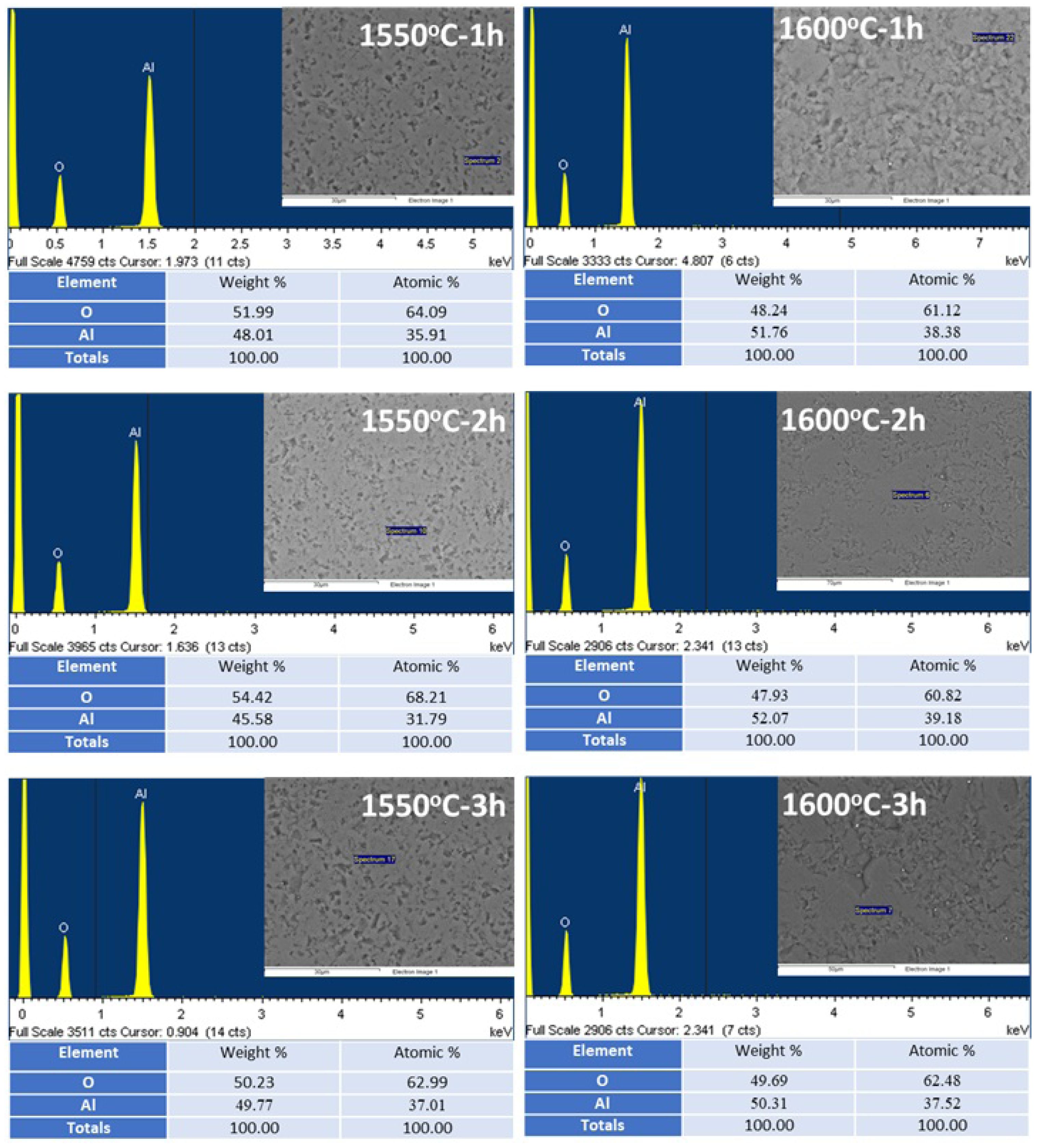
Examining the EDX chemical analysis results from the grains in all the sintered bodies in Fig. 6 revealed that the EDX spectra only contained peaks corresponding to Al and O, indicating the presence of the α-Al2O3 phase in the microstructure. This result supports the presence of the α-Al2O3 phase recorded in Fig. 1(a) and Fig. 3, from the reactive alumina powder itself and from the sintered bodies produced using this powder, respectively. Additionally, the EDX spectra in Fig. 6 clearly indicate that the reactive α-Al2O3 powder in this study was densified solely through conventional solid-state sintering, without the use of sintering additives. According to standardless EDX quantitative chemical analysis [62] results (Fig. 6), the stoichiometric ratios of α-Al2O3 grains developing in the microstructure were also determined to be 45-52 wt.% (31-39 at.%) Al and 48-54 wt.% (61-68 at.%) O.
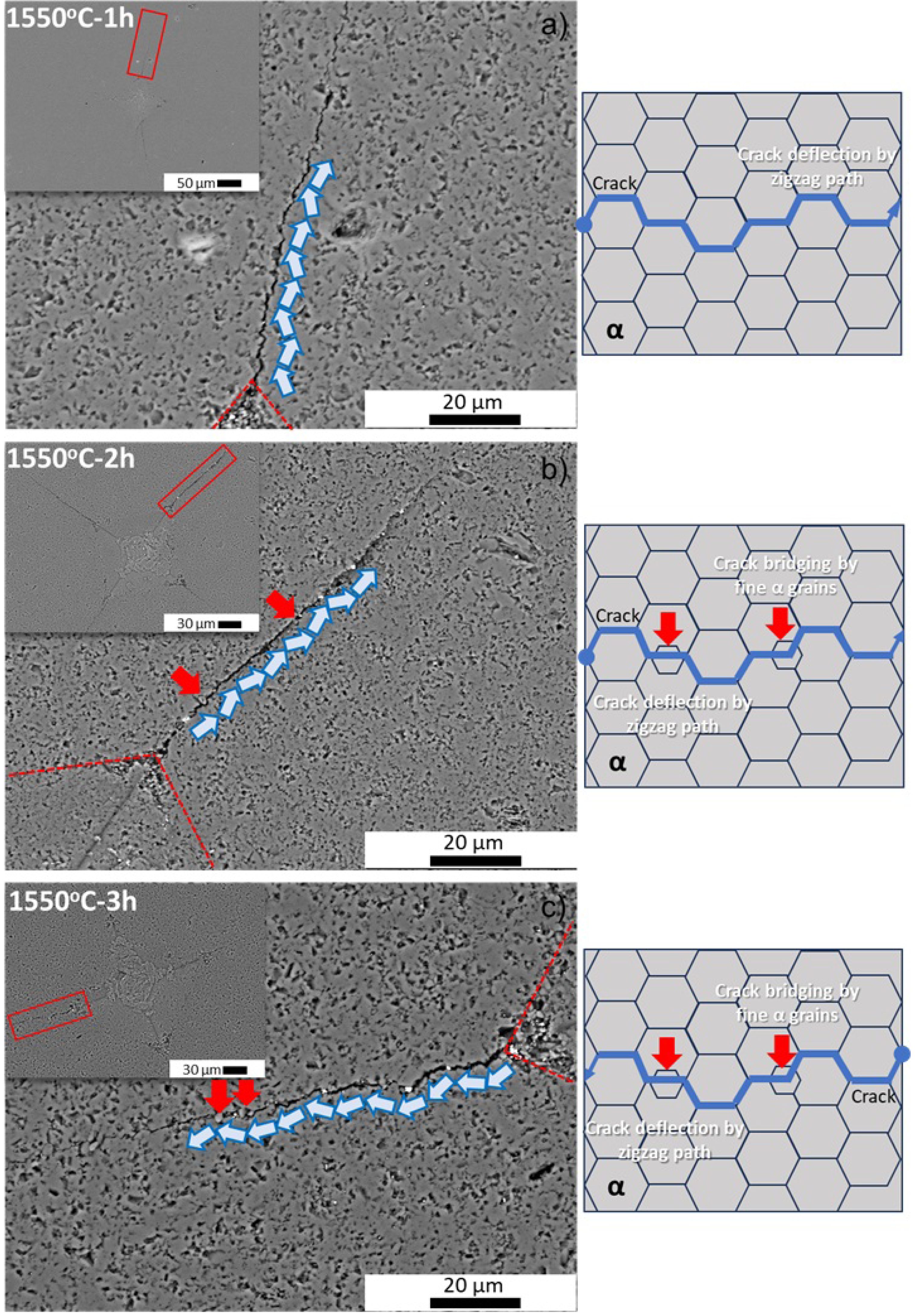
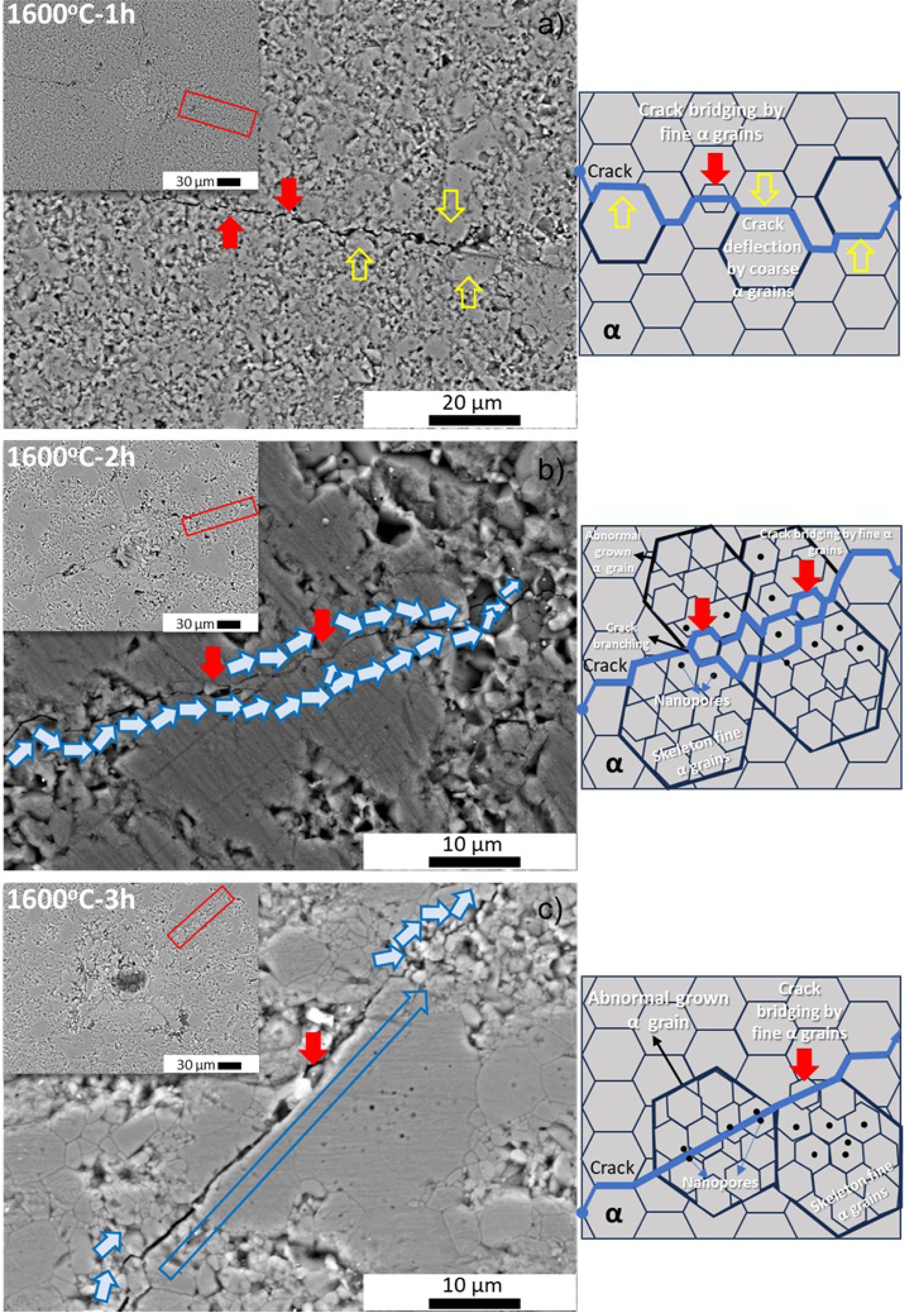
To gain a deeper understanding of the increased indentation Kıc values of sintered reactive α-Al2O3 bodies, the Vickers indentation traces of all sintered samples were examined by using SEM. In line with this objective, SEM images of sintered bodies recorded at 1550 °C and 1600 °C for 1 h, 2 h, and 3 h are shown in Fig. 7(a-c) and Fig. 8(a-c), respectively.
When the SEM images are analyzed collectively (see Figs. 7(a-c) and 8(a-c)), the Vickers diamond pyramid indenter trace and the cracks that form at the four corners of the indentations and propagate along the microstructure become clearly discernible in the inset SEM images. Upon closer inspection of the SEM images at higher magnifications, the cracks depicted within the red rectangle in the inset SEM images reveal that cracks formed in sintered reactive α-Al2O3 bodies generally follow a zigzag path along grain boundaries and predominantly propagate intergranularly, with crack deflection being the dominant mechanism. The simplest form of this mechanism is illustrated in the SEM image of the sintered body at 1550 °C for 1 hour, as well as in the schematic drawing of crack propagation derived from it (Fig. 7(a)). More interestingly, considering the SEM images and crack propagation diagrams of the sintered bodies at 1550 °C for 2 h and 3 h (Fig. 7(b) and Fig. 7(c)), the finer reactive α-Al2O3 grains located at grain boundaries (indicated by red arrows) play an additional role in hindering the energy of the intergranular crack propagating via crack bridging. At this point, the bimodal PSD of the initial reactive α-Al2O3 powder (Fig. 1(d)) caused an increase in the indentation Kıc of the sintered bodies. By increasing the sintering temperature to 1600 °C, the cracks propagating along the grain boundaries of the normally grown reactive α-Al2O3 grains, which developed in the microstructure due to increased densification (shown by yellow hollow arrows in Fig. 8(a)), lost a large portion of their energy due to traveling a longer distance. Thus, compared to the sample sintered at 1550 °C-1 h, an 11.5% higher Kıc value was obtained in the sintered body at 1600 °C-1 h due to normal grain growth (Table 2). At 1600 °C for 2 hours, cracks propagated in a zigzag pattern along the grain boundaries of abnormally grown α-Al2O3 grains, which contained nano-pores and whose skeletal structure was primarily formed by fine reactive α-Al2O3 grains (Fig. 8(b)). During this progression, the fine reactive α-Al2O3 grains, located at the grain boundaries, also reduced the crack energy by causing both crack branching and crack bridging (Fig. 8(b)). At 1600 °C-3 h, crack propagation exhibited intergranular crack deflection in the α-Al2O3 grain boundary region, which developed due to densification (indicated by short solid blue arrows on the SEM image), while it was determined to be transgranular character in abnormally grown α-Al2O3 grains (blue hollow long arrow on the SEM image) (Fig. 8(c)). However, as the crack propagates through the abnormally grown α-Al2O3 grain, it is thought that a large portion of its energy is absorbed due to the nano-pores within these exaggeratedly grown grains and the skeletal structure formed by the fine α-Al2O3 grains. Indeed, when cracks propagate transgranularly in abnormally grown grains, they cause an increase in fracture toughness because they expend a large portion of their energy by forming a new crack nucleation within the grain [63]. Thus, it has been reported that increasing grain size, particularly with the inclusion of some large grains, is crucial for achieving high fracture toughness [63]. This situation helps to explain why the body containing abnormal grain growth sintered at 1600 °C for 3 hours had the highest Kıc value (4.19±0.62 MPa·m1/2). The bridging of cracks by fine α-Al2O3 grains along the crack propagation path also contributed to the increase in toughness (red arrows in Fig. 8(c)). Although exaggerated or abnormal grain growth in polycrystalline alumina is often associated with mechanical degradation and increased strength scatter, this relationship is not universal and depends strongly on the accompanying microstructural features. In α-Al2O3 ceramics sintered at elevated temperatures, abnormal grain growth has frequently caused reduced flexural strength due to flaw enlargement and weakened grain boundaries [64]. However, when exaggerated grains form within a dense matrix containing fine residual porosity or hierarchical grain structures, such microstructural evolution can instead enhance fracture resistance [65-66]. In the present study, alumina ceramics sintered at 1600 °C for 3 h exhibited locally enlarged grains without a concomitant deterioration in mechanical properties; conversely, both fracture toughness and flexural strength were improved. This behavior can be efficient by considering the interactions between cracks and microstructure. Large alumina grains formed through the collapse and coalescence of finer grains may encapsulate nano-sized pores or remnant sub-grain boundaries, which act as crack-energy dissipation sites. Similar mechanisms, including crack deflection, crack bridging, and localized crack trapping, result in enhanced damage tolerance in the coarse-grained alumina systems despite increased grain size [67, 68]. Thus, the exaggerated grains in the present sintered reactive alumina ceramics do not behave as critical flaws but rather as energy-absorbing units that mitigate stress concentration at crack tips. These findings are consistent with reports indicating that abnormal grain growth does not inherently induce mechanical property scatter, provided that pore morphology, grain boundary cohesion, and grain size distribution are well controlled [69]. Therefore, aberrant grain growth in sintered reactive alumina ceramics should be evaluated in the context of its overall microstructural architecture, rather than being regarded a priori as detrimental.
Table 2 shows the measured values for the L, a, b, and ΔE parameters related to the color properties of sintered reactive α-Al2O3 bodies. Accordingly, depending on the sintering temperature and dwell time, the values of sintered dense bodies were determined to be between L: ≈90-95, a: ≈0-1.70, b: ≈9-12, and ΔE: ≈0-3.83. Depending on the sintering process parameters (temperature and holding time), there is a noticeable fluctuation in the L, a, and b values of sintered reactive α-Al2O3 bodies within a very narrow range. This fluctuation is accompanied by a decrease in pore volume within the microstructure, as the density increases, and an increase in the average grain size of the alumina grains. These changes may have affected light scattering, absorption, and diffraction. In sintered α-Al2O3 ceramics, exaggerated or abnormal grain growth primarily impacts the CIE L* value through alterations in light scattering resulting from diminished grain-boundary density and modified pore–grain size relationships, as opposed to via chemical coloration mechanisms [70, 71]. According to classical light-scattering models for polycrystalline alumina, an increase in grain size has been shown to result in a reduction of diffuse reflectance, leading to a decrease in optical lightness even at high relative densities [70]. Conversely, the a* and b* coordinates of high-purity alumina typically remain close to zero. The influence of grain growth on these materials is minimal unless defects are formed or impurities redistributed during high-temperature sintering [71, 72]. Therefore, variations in L*a*b* values associated with abnormal grain growth should be interpreted as microstructure-driven optical effects rather than indicators of compositional changes.
Indeed, in a study conducted by Zhao et al. on dental/semi-transparent alumina restoration ceramics [73], they reported that sintered dense bodies varied between L: ≈10-50, a: ≈0-(-2), and b: ≈0-(-8) values, especially depending on microstructural changes and the thickness of the sample being examined. The body sintered at 1550 °C for 1 hour was also used as an internal standard when calculating the ΔE values in this study. This allows for a direct comparison of the sintering process variables (temperature and holding time) within themselves. The fact that the ΔE values for the sintered bodies in Table 2 are mostly ˂1.5 indicates that the sintering process variables do not have a visible effect on color change [74]. This result is significant in terms of the potential use of sintered reactive α-Al2O3 ceramics, which exhibit color stability and sufficient physico-mechanical properties, in various new application areas such as radiation shielding in tile/panel or castable brick/block form.
Radiation shielding characteristics of sintered reactive alumina ceramics
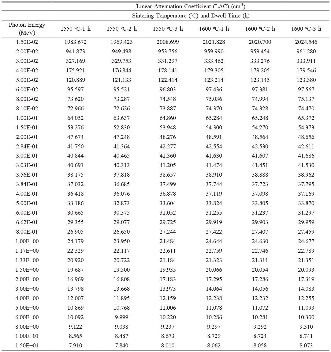
Table 3 represents the linear attenuation coefficient (LAC) values of sintered reactive α-Al2O3 samples produced under varying sintering conditions, where only the temperature (1550 °C and 1600 °C) and dwell time (1 h, 2 h, and 3 h) differ. The chemical compositions of the sintered samples are identical. Therefore, the differences in LAC arise solely from the changes in sintering temperature, dwell time, and resulting bulk density (ρBD). The measured precise ρBD values used in the LAC calculations are 3.8680 g.cm-3 for 1550 ⁰C-1 h, 3.8315 g.cm-3 for 1550 ⁰C-2 h, 3.9168 g.cm-3 for 1550 ⁰C-3 h, 3.9424 g.cm-3 for 1600 ⁰C-1 h, 3.9402 g.cm-3 for 1600 ⁰C-2 h, and 3.9477 g.cm-3 for 1600 ⁰C-3 h.
A general evaluation of the results shows that increasing the temperature from 1550 ⁰C to 1600 ⁰C consistently leads to slightly higher LAC values across all photon energies. This is attributed to higher densification achieved at elevated temperatures, which reduces porosity and increases the atomic packing density, both of which positively affect the material’s attenuation capability. For example, at 0.02 MeV, the LAC increases from 941.873 cm-1 for the 1550 ⁰C-1 h sample to 959.990 cm-1 for the 1600 ⁰C-1 h sample, clearly demonstrating the beneficial effect of higher temperature on gamma-ray shielding.
The effect of duration at each temperature also reveals interesting trends. At 1550 ⁰C, LAC values slightly decrease from 1h to 2h, consistent with a decrease in density from 3.8680 to 3.8315 g.cm-3, possibly due to structural relaxation or increased porosity during prolonged dwelling time. However, further increasing the duration to 3 h leads to an increase in LAC values, which coincides with the recovery of density to 3.9168 g.cm-3, suggesting enhanced densification over time. In contrast, at 1600 ⁰C, the duration effect is significantly less pronounced. The densities remain relatively stable across all durations, and LAC values show only marginal increases from 1 hour to 3 hours, with the 1600 oC-3 h sample exhibiting the highest LAC due to its slightly higher density (3.9477 g.cm-3). These observations suggest that densification is completed earlier at higher temperatures, and further holding time yields minimal benefits in terms of attenuation properties.
A clear and direct correlation is observed between ρBD and LAC. Samples with higher densities consistently exhibit higher LAC values across all photon energies. For instance, at 0.05 MeV, the LAC increases from 121.133 cm-1 in the 1550 ⁰C-2 h sample (3.8315 g.cm-3) to 122.414 cm-1 in the 1550 ⁰C-3 h sample (3.9168 g.cm-3). This correlation remains valid for the 1600 °C samples as well, with the 3-hour duration consistently producing the highest attenuation values. Additionally, as expected from fundamental principles of photon-matter interaction, LAC values decrease with increasing photon energy across all samples. The differences between samples are more pronounced at lower energies (below 0.1 MeV) and diminish at higher energies (above 1 MeV).
When focusing specifically on energy levels commonly used in radiation shielding studies—0.662 MeV (Cs-137) and 1.173 MeV and 1.332 MeV (Co-60)—the same trends persist. At 0.662 MeV, LAC values for 1550 ⁰C samples range from 29.077 cm-1 (2 h) to 29.725 cm-1 (3 h), while for 1600 ⁰C samples, they vary slightly between 29.903 cm-1 (2h) and 29.959 cm-1 (3 h). Similarly, at 1.173 MeV, LAC values increase from 22.117 cm-1 at 1550 ⁰C-2 h to 22.611 cm-1 at 1550 ⁰C-3 h, and from 22.746 cm-1 at 1600 ⁰C-2 h to 22.789 cm-1 at 1600 ⁰C-3 h. At 1.332 MeV, the same pattern is observed: 20.722 cm-1 at 1550 ⁰C-2 h increasing to 21.184 cm-1 at 1550 ⁰C-3 h, while 1600 ⁰C samples maintain stable values around 21.311-21.351 cm-1. These findings confirm the strong correlation between density and LAC, with higher densities yielding higher LAC values even at energies typical for practical gamma shielding assessments.
In brief, increasing the temperature from 1550 ⁰C to 1600 ⁰C improves the radiation shielding performance due to better densification and higher density. While duration affects LAC at 1550 ⁰C by initially decreasing and then increasing LAC through progressive densification, its impact is negligible at 1600 ⁰C because high density is already achieved early in the process. The density differences are mirrored directly in LAC behavior, confirming density as the dominant factor governing gamma attenuation. Overall, the 1600 °C-3 h sample exhibits the best shielding performance due to its highest density and most stable structure. However, the performance differences between 1 h, 2 h, and 3 h at 1600 °C are marginal, suggesting that temperature exerts a more decisive influence than duration on the LAC characteristics of sintered reactive α-Al2O3 ceramic materials.
Considering the limited number of studies conducted in the literature on radiation shielding with Al2O3, it has been recorded that the LAC value of unsintered plate-shaped samples containing 100% Al2O3 is 0.105 cm⁻¹ at 0.662 MeV [28]. In addition, in epoxy resin composites containing Al2O3 nanoparticles (NPs), when the Al2O3 NPs content was increased from 3 wt.% to 20 wt.%, the LAC value of the composites at 0.059 MeV energy increased from 0.59 cm⁻¹ to 3.04 cm⁻¹ [21]. In ZrSiO4-Al2O3 composites where Al2O3 was used at a maximum concentration of 50% wt., LAC values were determined to be 0.209 cm⁻¹ at 0.662 MeV, 0.150 cm⁻¹ at 1.173 MeV, and 0.043 cm⁻¹ at 1.332 MeV [27].
In addition, the shielding performance of sintered reactive α-Al2O3 ceramics was compared with conventional radiation shielding materials in terms of attenuation efficiency per unit thickness and corresponding areal mass. Ordinary Portland cement concrete typically has a density between 2.30 and 2.45 g.cm-3, while densified heavy concretes (e.g., concrete with barite or hematite aggregates) reach 2.9-3.5 g.cm-3 depending on aggregate loading [75-78]. In this study, sintered reactive alumina monoliths achieve ρBD = 3.94-3.95 g.cm-3 due to high density and low residual porosity, leading to significantly stronger photon-matter interaction per unit thickness. In XCOM-based photon mass attenuation calculations, under the same assumed narrow beam geometry, a dense α-Al2O3 monolith 10 mm thick provides similar or higher theoretical attenuation compared to heavy barite/hematite concrete 30-50 mm thick. This means that equivalent photon attenuation can be achieved with 40-60% less thickness and a proportionally lower field weight. Although monolithic oxides with very high Z, such as PbO or Bi2O3, perform better than alumina in the >1 MeV region, they introduce disadvantages, including excessive density (ρ = 8.0-9.5 g.cm-3), opacity, and mechanical brittleness in their monolithic form [79-82]. Therefore, alumina ceramics provide a practical medium-density shielding solution, particularly for weight- and thickness-sensitive monolithic shields or ceramic matrix composites (CMCs). Here, attenuation per unit thickness is significantly improved compared to concrete, while superior mechanical integrity, optical neutrality, and chemical stability are maintained. This comparison highlights that sintered reactive α-Al2O3 can effectively function as a monolithic shielding layer at thicknesses lower than those of concrete, or as a highly stable structural matrix for next-generation radiation shielding CMCs, where both thickness-normalized attenuation and durability are critical. To the best of our knowledge, this study is the first to calculate LAC values from sintered reactive α-Al2O3 ceramics, which depend on the sintering process parameters (temperature and holding time). It is expected to facilitate the development of next-generation monolithic alumina ceramics or alumina-based ceramic matrix composites (CMCs) for radiation shielding.
|
Fig. 3 a) XRD diagrams of the bulk samples obtained after sintering of reactive alumina powder at 1550 °C and 1600 °C for 1h, 2h, and 3h, and b) the crystal structure of corundum (α-Al2O3) (drawn using Jmol software [45]). |
|
Fig. 4 SEM images of the samples obtained after sintering of reactive alumina powder at 1550 °C and 1600 °C for 1 h, 2 h, and 3 h. |
|
Fig. 5 Histograms of the average grain size distribution of α-Al2O3 grains calculated from the SEM images in Fig. 4. |
|
Fig. 6 EDX spectra and semi-quantitative analysis results (the inset SEM image shows where the EDX analysis was taken from) of bulk samples after sintering of reactive alumina powder at 1550 °C and 1600 °C for 1 h, 2 h, and 3 h. |
|
Fig. 7 SEM images showing the Vickers indentation traces, crack propagation along the microstructure, and their schematic representations of the sintered reactive α-Al2O3 bodies at 1550 °C for a) 1 h, b) 2 h, and c) 3 h. |
|
Fig. 8 SEM images showing the Vickers indentation traces, crack propagation along the microstructure, and their schematic representations of the sintered reactive α-Al2O3 bodies at 1600 °C for a) 1 h, b) 2 h, and c) 3 h. |
|
Table 3 The LAC values obtained from Phy-X/PSD software for sintered reactive α-Al2O3 bodies. |
This study marks the first time that the traditional solid-state sintering method has been used without auxiliary sintering additives from reactive α-Al2O3 starting powder at temperatures of 1550 °C and 1600 °C for durations of 1 h, 2 h, and 3 h. Subsequently, the physico-mechanical, phase, microstructure, sinterability, and radiation shielding properties of the sintered bodies have been systematically investigated. The results obtained in this context are summarized below.
According to the detailed characterization data obtained from the reactive alumina powder used in the study, the powder has a corundum (α-Al2O3) crystal structure, high purity (99.31 wt.%), an average particle size distribution (Dv(50)) of 3.22 µm, bimodal equiaxed particle shape, and a specific surface area of 9.193 m2/g.
Depending on the increasing sintering temperature and holding time, the sintered reactive α-Al2O3 bodies have been sintered to ≥97.00% of their theoretical density (TD). The highest relative density value (ρRD=99.94%) was achieved in the S6 body sintered at 1600 °C for 3 hours.
The XRD analysis results of sintered reactive α-Al2O3 bodies show that the single phase in all samples after sintering is the α-Al2O3 phase with a corundum crystal structure. The comprehensive SEM microstructure and EDX qualitative and semi-quantitative chemical analysis observations confirmed the presence of the α-Al2O3 phase developed as a consequence of sintering within the microstructure.
Concurrently, SEM images obtained from sintered reactive α-Al2O3 bodies demonstrated that elevating the sintering temperature and holding time led to denser and more compact microstructures, a reduction in porosity, and an increase in the average grain size of α-Al2O3 grains. In particular, abnormal grain growth has been determined in sintered samples at 1600 °C for 2h and 3 h. In these abnormally growing grains, fine reactive α-Al2O3 grains with a bimodal character also form a skeletal structure.
An evaluation of the samples in terms of mechanical properties (Vickers hardness (Hv), indentation fracture toughness (Kıc), and flexural strength (σ)) revealed a clear trend. As the sintering temperature and holding time increased, the Hv values of the sintered reactive α-Al2O3 bodies decreased, while the Kıc and σ values increased. The highest Hv value (18.37±0.45 GPa) was recorded in the S1 sample sintered at 1550 °C for 1 hour, while the best Kıc and σ values were observed in the S6 sample sintered at 1600 °C for 3 hours, with values of 4.19±0.62 MPa·m1/2 and 387±37 MPa, respectively.
A thorough SEM examination of the Vickers indentation traces revealed the presence of various mechanisms, including crack deflection, crack bridging, crack branching, intragranular nanopores, and the skeletal structure formed by fine reactive α-Al2O3 grains within abnormally grown alumina grains, which play a key role in the increase of Kıc values in sintered reactive α-Al2O3 structures.
The L: ≈90-95, a: ≈0-1.70, b: ≈9-12, and ΔE: ≈0-3.83 values were determined in the sintered reactive α-Al2O3 bodies as a function of increasing sintering temperature and dwell time.
The linear attenuation coefficient (LAC) values of all sintered reactive α-Al2O3 bodies were calculated for radiation shielding applications. Accordingly, higher LAC values were obtained for all photon energies studied as the sintering temperature increased. However, the beneficial impact of dwell time on LAC was determined to be less pronounced. The best LAC values in terms of gamma-ray shielding were recorded at 29.959 cm⁻¹ (@0.662 MeV), 22.789 cm⁻¹ (@1.173 MeV), and 21.351 cm⁻¹ (@1.332 MeV) in the S6 sample sintered at 1600 °C-3 h.
In consideration of the findings documented in this study, sintered reactive α-Al2O3 ceramics have been demonstrated to exhibit several noteworthy attributes. These ceramics are characterized by their cost-effectiveness, ease of production, and exceptional color stability. Additionally, they are renowned for their high physico-mechanical properties and LAC values. These properties position them as promising candidates for the fabrication of alumina-based sintered monolithic or ceramic matrix composites (CMCs), particularly in the context of gamma-ray radiation shielding applications.
I would like to express my gratitude to Kütahya Dumlupınar University Advanced Technologies Design, Research-Development and Application Center (DPÜ-İLTEM), the Eskişehir Ceramics Research Center (SAM), the Department of Materials Science and Engineering at Eskişehir Technical University, and Teknoceram Ltd. Şti. for their infrastructure activities used during the implementation phase of production, testing, and analysis of this study. I would also like to express my sincere gratitude to Prof. Dr. Taner Kavas and Assist. Prof. Dr. Recep Kurtuluş from the Department of Materials Science and Engineering at Afyon Kocatepe University, for their significant contributions to radiation shielding research.
- 1. D. Tang, H.B. Lim, K.J. Lee, S.J. Ha, K.B. Kim, M.W. Cho, K. Park, and W.S. Choa, J. Ceram. Process. Res. 14[5] (2013) 610-615.
-

- 2. Q. Tian, J. Dai, Z. Lv, and T. Zhai, J. Ceram. Process. Res. 17[7] (2016) 676-680.
-
- 3. E.R. Rangel, E.R. García, J.G.M. Hernández, and E.T. Rojas, J. Ceram. Process. Res. 10[6] (2009) 744-747.
-
- 4. A. Rittidech and A. Suthapintu, J. Ceram. Process. Res. 25[1] (2024) 22-27.
-
- 5. A. Di, J. Ceram. Process. Res. 26[5] (2025) 803-806.
-
- 6. Y. Wang, H. Yang, Z. Pei, B. Shen, J. Shao, M. Mukhtar, Z. Ma, H. Gleiter, Y. Dong, T. Ma, and J. Li, Acta Mater. 277 (2024) 120166.
-
- 7. I. Zmak, D. Coric, V. Mandic, and L. Curkovic, Mater. 13[1] (2020) 122.
-
- 8. S.B. Gürel, and A. Altun, Powder Technol. 196[2] (2009) 115-121.
-
- 9. M.A. Trubitsyn, N.A. Volovicheva, L.B. Furda, V.I. Kuzin, and R.V. Zubashchenko, Refract. Ind. Ceram. 63[2] (2022) 130-136.
-
- 10. M.A. Trubitsyn, N.A. Volovicheva, L.B. Furda, V.I. Kuzin, and R.V. Zubashchenko, Refract. Ind. Ceram. 63[2] (2022) 137-142.
-
- 11. S. Ghose, C. Saigal, A. Maldhure, and S.K. Das, T. Indian Ceram. Soc. 72[2] (2013) 113-118.
-
- 12. Y.E. Pivinskii, P.V. Dyakin, and A.Y. Kolobov, Refract. Ind. Ceram. 58[1] (2017) 103-108.
-
- 13. V. Viswabaskarana, F.D. Gnanama, and M. Balasubramanian, Appl. Clay Sci. 25[1-2] (2004) 29-35.
-
- 14. V. Viswabaskarana, F.D. Gnanama, and M. Balasubramanian, Ceram. Int. 29[5] (2003) 561-571.
-
- 15. V. Viswabaskaran, F.D. Gnanama, and M. Balasubramanian, J. Mater. Process. Technol. 142[1] (2003) 275-281.
-
- 16. W. Yuan, H. Tang, Y. Zhou, and D. Zhang, Ceram. Int. 44[5] (2018) 5032-5036.
-
- 17. D. Zhang, C. Li, N. Jiang, J. Gao, B. Touzo, and Wenjie Yuan, Ceram. Int. 44[8] (2018) 9984-9990.
-
- 18. A. Badolia, R. Sarkar, and S.K. Pal, Bull. Mater. Sci. 38[4] 2015 975-983.
-
- 19. D. Madej and J. Szczerba, Ceram. Silik. 60[2] (2016) 27-33.
- 20. H. Tang, Y. Shi, and W. Yuan, Process. Appl. Ceram. 16[1] (2022) 1-6.
-
- 21. R. Darwesh, M.I. Sayyed, Y. Al-Hadeethi, H.J. ALasali, and J.S. Alotaibi, Ann. Nucl. Energy 200[1] (2024) 110385.
-
- 22. M.I. Sayyed, J.F.M. Jecong, F.C. Hila, C.V. Balderas, A.M.S. Alhuthali, N.R.D. Guillermo, and Y. Al-Hadeethi, Ceram. Int. 47[9] (2021) 13181-13186.
-
- 23. F. Akman, Z.Y. Khattari, M.R. Kaçal, M.I. Sayyed, and F. Afaneh, Radiat. Phys. Chem. 160 (2019) 9-14.
-
- 24. A.M. Osman, ASME J. Nucl. Radiat. Sci. 9[1] (2023) 012002.
-
- 25. A.S. Aliyu, L.J. Utume, S. Muhammad, M.S. Iorshase, E.O. Adamu, S.W. Oyeyemi, I. Pada, and Y. Musa, Radiat. Phys. Chem. 238 (2026) 113144.
-
- 26. U. Gökmen, Z. Özkan, U. Taşcı, and S.B. Ocak, Phys. Scr. 97[5] (2022) 055307.
-
- 27. M. Gharieb, S.H. Kenawy, G.T. El-Bassyouni, and E.M.A. Hamzawy, Part. Sci. Technol. 41[2] (2023) 250-260.
-
- 28. S.I. Jubair and A.H. Al-Mashhadani, Nucl. Instrum. Methods Phys. Res. B 529 (2022) 7-11.
-
- 29. R. Arya, R. Paulose, V. Agrawal, A. Pandey, D. Mishra, S.K. Sanghi, M. A. Khan, D.P. Mondal, M.M. Shafeeq, K. Banerjee, S. Chatterjee, S. Mukhopadhyay, P. Roy, R. Ravishankar, C. Bhattacharya, A. Bhisikar, P. Mondi, U. Singh, A. Agnihotri, A.K. Srivastava, and S.T. Salammal, Constr. Build. Mater. 373 (2023) 130895.
-
- 30. R. Ge, Y. Zhang, Y. Liu, J. Fang, W. Luan, and G. Wu, J Mater Sci: Mater Electron 28[8] (2017) 5898-5905.
-
- 31. ASTM B 962-17 (2017) Standard test methods for density of compacted or sintered powder metallurgy (PM) products using Archimedes’ principle. ASTM International
-
- 32. A. Yurdakul and O. Balci, Adv. Compos. Hybrid Mater. 4[2] (2021) 415-434.
-
- 33. S. Suprapedi, M. Muljadi, and P. Sardjono, IOP Conf. Ser. Mater. Sci. Eng. 299 (2018) 8012043.
-
- 34. ISO/CIE 11664-4:2019, Colorimetry-Part 4: CIE 1976 L*a*b* colour space.
-
- 35. M. Rioseco and S. Wagner, Int. J. Inter. Dent. 14[3] (2021) 233-236.
-
- 36. ASTM E384–10-Standard test method for microindentation hardness of materials. ASTM International; 2010.
-
- 37. K. Niihara, J. Mater. Sci. Lett. 2 (1983) 221-223.
-
- 38. K. Niihara, R. Morena, and DPH Hasselman, in Fracture mechanics of ceramics (Plenum, New York, 1983) p. 97-105.
-
- 39. W. Pabst, G. Ticha, and E. Gregorova, Ceram. Silik. 48[2] (2004) 41-48.
- 40. ASTM C1161–13 Standard test method for flexural strength of advanced ceramics at ambient temperature. ASTM International; 2013.
-
- 41. R. Kurtulus, M.I. Sayyed, T. Kavas, K.A. Mahmoud, O.L. Tashlykov, M.U. Khandaker, and D.A. Bradley, Radiat. Phys. Chem.186 (2021) 109557.
-
- 42. C.A. Schneider, W.S. Rasband, and K.W. Eliceiri, Nat. Methods. 9[7] (2012) 671-675.
-
- 43. Z. He, J. Ma, Ceram. Int. 27[3] (2001) 261-264.
-
- 44. K. Yahiaoui, S. Messaoud Aberkane, and A. Naitbouda, Mater. Chem. Phys. 259[1] (2021) 124045.
-
- 45. Jmol: an open-source Java viewer for chemical structures in 3D. http://www.jmol.org/
- 46. E. Eberhardt, B. Stimpson, and D. Stead, Rock Mech. Rock Engng. 32[2] (1999) 81-99.
-
- 47. K. Maiti and A. Sil, Ceram. Int. 36[8] (2010) 2337-2344.
-
- 48. P. Gao, S. Zeng, C. Jin, B. Zhang, B. Chen, Z. Yang, Y. Guo, M. Liang, J. Li, W. Wang, Y. Lu, L. Jia, and D. Zhao, Coatings 12[2] (2022) 165.
-
- 49. I. Ganesh, G. Sundararajan, S.M. Olhero, P.M.C. Torres, and J. M.F. Ferreira, Ceram. Int. 36[4] (2010) 1357-1364.
-
- 50. J. Li, Y. Pan, F. Qiu, L. Huang, and J.Guo, Mater. Sci. Eng. A 435-436 (2006) 611-619.
-
- 51. J.F. Roy, M. Descemond, C. Brodhag, and F. Thevenot, J. Eur. Ceram. Soc. 11[4] (1993) 325-333.
- 52. B.A. Latella and B.H. O'Connor, J. Mater. Sci. 33 (1998) 877-886.
-
- 53. V. Milan, I. Žmak, L. Ćurković, and A. Kocjan, Mater. 15[21] (2022) 7840.
-
- 54. K.Y. Lee, P.H. Dearhouse, and E.D. Case, J. Mater. Synth. Process. 7 (1999) 159-166.
-
- 55. M. Vukšić, I. Žmak, L. Ćurković, and A. Kocjan, Open Ceram. 5 (2021) 100076.
-
- 56. S. Yang, S. Yang, Y. Zhu, L. Fan, and M. Zhang, J. Eur. Ceram. Soc. 42[1] (2022) 202-206.
-
- 57. B. Suleiman, H. Zhang, Y. Ding, and Y. Li, Ceram. Int. 48[10] (2022) 13531-13540.
-
- 58. T.F. Ariff, A.Z. Azhar, M.N. Sariff, S.N. Rasid, S.Z. Zahari, R. Bahar, M. Karim, and A.K.M. Nurul Amin, IOP Conf. Ser.: Mater. Sci. Eng. 290 (2018) 012044.
-
- 59. R. Yanga, Z. Qi, Y. Gao, J. Yang, Y. Zhou, H. Liu, L. Peng, and J. Jiao, Ceram. Int. 46[13] (2020) 20865-20870.
-
- 60. G.R. Karagedov and A.L. Myz, J. Eur. Ceram. Soc. 32 (2012) 219-225.
-
- 61. S.I. Bae and S. Baik, J. Mater. Sci. 28 (1993) 4197-4204.
-
- 62. D.E. Newbury, C.R. Swyt, and R.L. Myklebust, Anal. Chem. 67[11] (1995) 1866-1871.
-
- 63. S. Zhao, J. Qiao, G. Sang, X. Xi and J. Yang, J. Am. Ceram. Soc. 107[7] (2024) 4705-4716.
-
- 64. R.L. Coble, J. Appl. Phys. 32[5] (1961) 787-792.
-
- 65. M. Trunec and V. Pouchly, Ceram. Int. 42[10] (2016) 11838-11843.
-
- 66. A. Krell, J. Am. Ceram. Soc. 81[7] (1998) 1900-1906.
-
- 67. F.F. Lange and T.K. Gupta, J. Am. Ceram. Soc. 53[1] (1970) 54-55.
-
- 68. D. Munz and T. Fett, in “Ceramics: Mechanical Properties, Failure Behavior, Materials Selection” (Springer, 1999).
-
- 69. M. Li, B. Tunca, B.V. Meerbeek, J. Vleugels, and F. Zhang, J. Eur. Ceram 43[5] (2023) 2078-2092.
-
- 70. R. Apetz and M.P.B. van Bruggen, J. Am. Ceram. Soc. 86[3] (2003) 480-486.
-
- 71. J.G.J. Peelen and R. Metselaar, J. Appl. Phys. 45[1] (1974) 216-220.
-
- 72. W.D. Kingery, H.K. Bowen, and D.R. Uhlmann, in “Introduction to Ceramics, 2nd ed.” (Wiley-Interscience, 1976).
- 73. M. Zhao, Y. Sun, J. Zhang, and Y. Zhang, J. Dent. Res. 97[3] (2018) 289-295.
-
- 74. M. Rioseco and S. Wagner, Int. J. Inter. Dent. 14[3] (2021) 233-236.
-
- 75. M.E. Desouky, A. Abdelaziz, M.E. Fransawy, and R.E. Sadany, Egypt. J. Chem. 66[11] (2023) 107-118.
-
- 76. Q. Wang, Y. Wang, B. Zhou, L. Wang, Y. Fang, and S. Xu, J. Build. Eng. 79 (2023) 107820.
-
- 77. B. Kanagaraj, N. Anand, S. Raj, and E. Lubloy, Clean. Eng. Technol. 19 (2024) 100733.
-
- 78. D.J. Niedzwiedzka, M.A. Glinicki, K. Gibas, and T. Baran, Materials (Basel) 11[11] (2018) 2284.
-
- 79. M.I. Sayyed, M.H.M. Zaid, N. Effendy, K.A. Matori, H.A.A. Sidek, E. Lacomme, K.A. Mahmoud, and M.M. AlShammari, J. Mater. Res. Technol. 9[4] (2020) 8429-8438.
-
- 80. Y.S. Rammah, K.A. Mahmoud, E. Kavaz, A. Kumar, and F.I.E. Agawany, Ceram. Int. 46[15] (2020) 23357-23368.
-
- 81. E. Hannachi, K.A. Mahmoud, Y. Slimani, and M.I. Sayyed, Ceram. Int. 48[17] (2022) 24355-24362.
-
- 82. D.K. Gaikwad, S.S. Obaid, M.I. Sayyed, R.R. Bhosale, V.V. Awasarmol, A. Kumar, M.D. Shirsat, and P.P. Pawar, Mater. Chem. Phys. 213 (2018) 508-517.
-
 This Article
-
2026; 27(1): 113-129
Published on Feb 28, 2026
- 10.36410/jcpr.2026.27.1.113
- Received on Oct 19, 2025
- Revised on Jan 6, 2026
- Accepted on Jan 9, 2026
Services
- Abstract
introduction
experimental studies
results and discussion
conclusions
- Acknowledgements
- References
- Full Text PDF
Shared
Correspondence to
- Arife Yurdakul
-
Department of Metallurgical and Materials Engineering, Faculty of Engineering, Kütahya Dumlupınar University, Kütahya, Türkiye
Tel : 00-90-274-443-4275 Fax: 00-90-274-265-2066 - E-mail: arife.yurdakul@dpu.edu.tr
Clean-Energy Research Institute(CRI), Hanyang University, 222, Wangsimni-ro, Seongdong-gu, Seoul, 04763, Korea
E-mail: jcpr@hanyang.ac.kr