


- Preparation of hierarchically porous silica ceramics using porous powders as raw materials and pore-forming agents
Weichun Changa, Chunman Lia, Xuewei Lia, Xin Zhanga, Xinshuang Guob,*, Guoxiang Zhouc and Haifeng Guob,*
aPipeChina Science and Technology Research Institute, Binhai Tianjin 610500, China
bEngineering & Technology Research Center for Environmental Protection Materials and Equipment of Jiangxi Province, College of Materials and Chemical Engineering, Pingxiang University, Pingxiang 337055, PR China
cAdvanced Ceramics and Intelligent Manufacturing Research Center, Chongqing Research Institute, Harbin Institute of Technology, Chongqing 401151, PR ChinaThis article is an open access article distributed under the terms of the Creative Commons Attribution Non-Commercial License (http://creativecommons.org/licenses/by-nc/4.0) which permits unrestricted non-commercial use, distribution, and reproduction in any medium, provided the original work is properly cited.
Hierarchically porous silica ceramics were prepared by gel casting using the pore structures of fly ash hollow spheres (FAHSs), diatomite and expanded perlite as non-sacrificial templates. The effects of the amount of dispersant and binder (sol), FAHS particle size, slurry composition and sintering temperature on the structure and properties of porous ceramics were investigated. Results showed that the structural inhomogeneity of porous ceramics could be avoided by using sodium carboxymethyl cellulose as dispersant. Using silica sol as binder and FAHSs, diatomite and perlite powder as main raw materials, the porous ceramics prepared at 1200 °C not only have obvious hierarchical pore structures, but also have low diameter shrinkage (1.99%), high compressive strength (18.54 MPa) and excellent thermal insulation. This paper provides a method to prepare hierarchical porous ceramics using porous inorganic powders as raw material and pore-forming agent, and addresses the resource utilization of porous powders represented by FAHSs.
Keywords: Porous ceramics, Hierarchical pore structure, Porous ceramic powders, Non-sacrificial templates, FAHS utilization.
Porous ceramics have been widely applied in gas filtration, solid/liquid separation and so on because of their porosity, low density and high temperature resistance [1-3], especially the hierarchically porous ceramics have attracted much attention in the fields of filtration and catalysis [4-6]. Generally, the raw materials for preparing porous ceramics are various solid high-density raw materials (SiC powders, Al2O3 particles, etc.) [7, 8] or liquid raw materials (polycarbosilane, boehmite sol, etc.) [9-11]. Porous ceramics can be achieved by combining the above-mentioned raw materials with main processing methods, such as direct foaming method [10, 12], sacrificial template method [13-15] and replica method [16-18], through the incorporation of pore structures into solid ceramics. When preparing porous ceramics with hierarchical pore structure, the above-mentioned pore-forming approaches were usually combined [12, 19, 20]. Liu et al. had fabricated hierarchical Al2O3 porous ceramics via the combined chemical grafting pore-forming agents and polyurethane foaming method [21]. However, it is difficult to control the process and pore uniformity in preparing porous ceramics by direct foaming method [22, 23]. In addition, when porous ceramics are prepared via sacrificial template method or replica method, the removal of the additives such as polymeric sponge or pore-forming agent could give rise to ceramic matrix damage and environmental problems [22, 24]. Therefore, it is urgent to develop a simple and feasible method for preparing porous ceramics with hierarchical pore structure.
Different from traditional methods for preparing porous ceramics, it is attractive to use hollow spheres as non-sacrificial pore-forming agent to prepare porous ceramics in recent years [25-27]. Using Al2O3 hollow spheres [28], SiO2 hollow spheres [29] and so on [26], the complete hollow sphere-based ceramics were obtained. Lightweight ceramic materials with hollow structures, such as fly ash hollow spheres (FAHSs) and diatomite, were usually made into porous ceramics by ball milling or high-pressure forming [30-33], which resulted in the destruction of the hollow structure of raw materials and additional energy consumption. Without destroying the pore structures of these porous materials, using them to prepare porous ceramics could simplify preparation process and reduce production cost [34, 35]. Chen et al. used selective laser sintering to solve the problem of preparing high-porosity mullite ceramic foams using FAHSs as raw materials [36]. However, it is still a challenge to simply prepare hierarchically porous ceramics using porous raw materials themselves as templates.
In this paper, the hierarchically porous SiO2 ceramics were prepared via gelcasting and ordinary sintering using lightweight FAHSs, diatomite and expanded perlite as main raw materials. Effect of dispersant addition on the dispersion of slurries was studied. The effects of raw material proportion, FAHS particle size, binder (sol) addition and sintering temperature on the structure and properties of porous ceramics were investigated.
Raw materials
FAHSs were produced by Hebei Yanxi Minerals Processing Plant. Diatomite was purchased from Henan Boxu Environmental Protection Technology Co., Ltd. The expanded perlite was provided by Xinyang Zhongsen Perlite Application Co., Ltd. The acrylamide, methylene bisacrylamide, dispersants (sodium carboxymethyl cellulose (CMC), polyethylene glycol and sodium polyacrylate), ammonium persulfate and tetramethylethylenediamine used in gelcasting process were all produced by Sinopharm Chemical Reagent Co., Ltd.. Aluminum sol, silica sol and aluminum-silica sol were all purchased from Dezhou Jinghuo Technology Glass Co., Ltd.
Sample preparation
First, FAHSs, diatomite, expanded perlite powders, acrylamide, methylene bisacrylamide, dispersant (0.06g) and ammonium persulfate were added to the glass beaker filled with 15 mL sol. The gelcasting process was described elsewhere [15]. Next, 120 μL tetramethylethylenediamine was added into the well-stirred mixture, and then it was casted into a polytetrafluoroethylene mold for curing. The cured green body was dried at 40 ℃ for 8 h. Finally, the dried green body was sintered at 1200 ℃ for 2 h to obtain porous ceramics. The slurry composition for preparing green bodies is shown in Table 1.
Characterization
The morphologies of porous ceramics were examined with a scanning electron microscope (SEM, S8010, Hitachi). Phase constitutions of the samples was tested by X-ray diffraction (XRD, D8 Advance, Bruker). The compressive strength of porous ceramics was performed on a universal testing machine (AGS-X-10 kN, Shimadzu). The porosity of the samples was determined by Archimedean method. Thermal insulation properties of porous ceramics (sizes of Φ40 mm×15 mm) was tested using a thermal constants analyzer (TPS 2500S, Sweden). The equations for calculating apparent porosity, diameter and height shrinkage are listed as below [36]:
where P0 is the apparent porosity, m0 is the dry mass of specimen, m is the mass of the sample after saturation with water, m1 is the mass of specimen after water absorption. D0 and H0 are the diameter and height shrinkage rate of the samples, respectively. d1 and h1 are the diameter and height of the green samples, and d2 and h2 are the diameter and height of the sintered samples, respectively.
Effect of dispersant addition on mechanical properties of porous ceramics
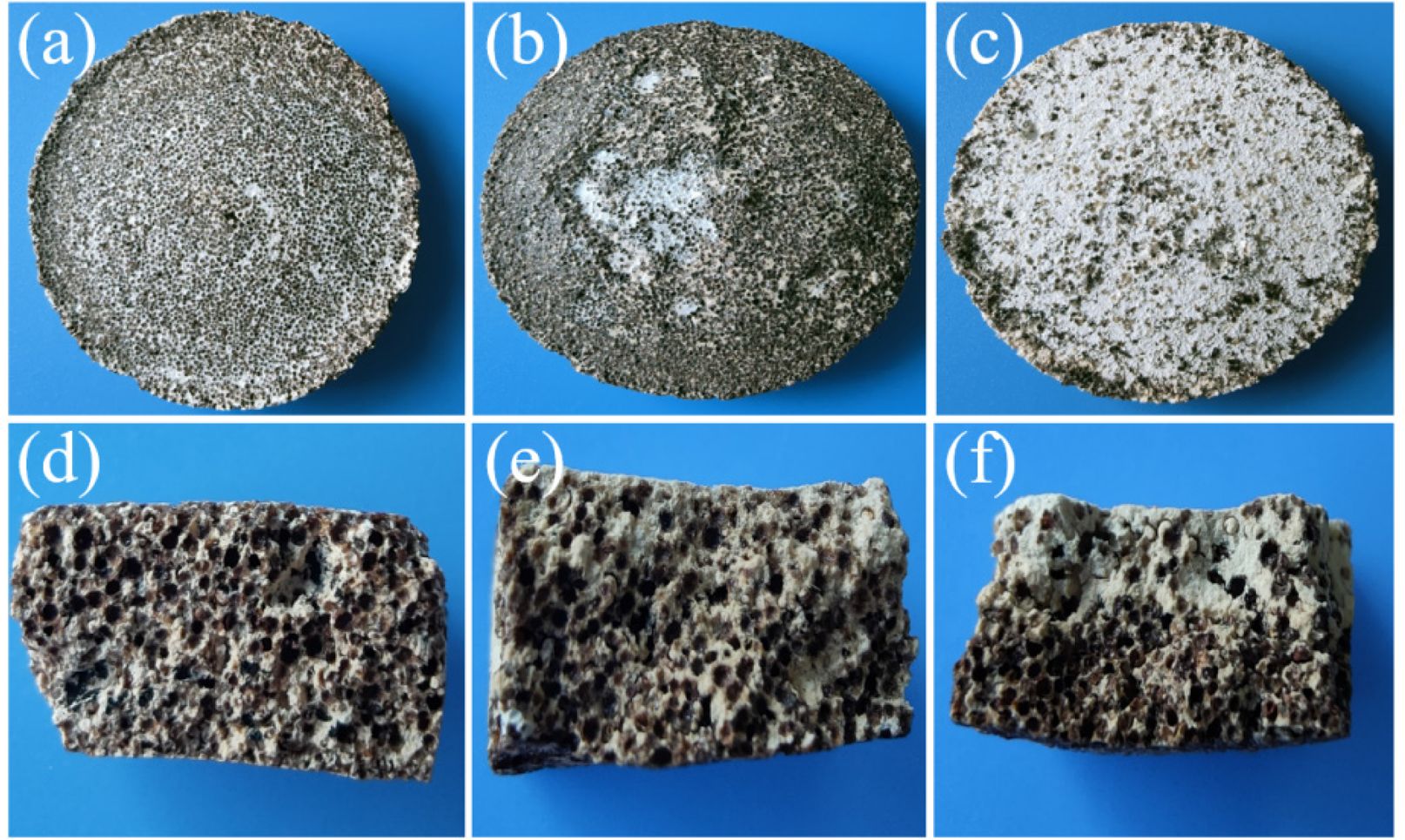
When CMC, sodium polyacrylate and polyethylene glycol are used as dispersants, the optical photos of the surface and cross section of porous ceramics prepared from P1 are shown in Fig. 1. In Fig. 1a and d, the color distribution on the surface and cross section of porous ceramics prepared with CMC as dispersant is uniform, and the upper and lower surfaces of samples are approximately straight. When polyethylene glycol is used as dispersant, the perlite and diatomite in the porous ceramics slightly float up and concentrate in the middle area of their upper surface (Fig. 1b), and the shape of porous ceramics is deformed (Fig. 1e), which is consistent with the reported results [37]. Overall, the porous ceramics exhibit an upward bending tendency, with a bending angle of approximately 7-12° relative to the horizontal plane. When sodium polyacrylate is used as a dispersant, the upper surface of the porous ceramic is white (Fig. 1c), and its cross-section also shows upward curvature with a bending angle of about 5-8°. Cross-sectional analysis reveals that the upper part is white while the lower part is relatively dark, indicating uneven dispersion of FAHSs within the slurry. The structural inhomogeneity of ceramic materials will affect its mechanical properties and easily cause bending deformation [38]. When the upper surface of the sample is enriched with lightweight expanded perlite and diatomite, the shrinkage of the upper surface during the sintering process exceeds that of the lower surface, ultimately resulting in upward bending deformation of the sample. Therefore, using CMC as dispersant is beneficial to prepare porous ceramics with uniform structure and good mechanical properties.
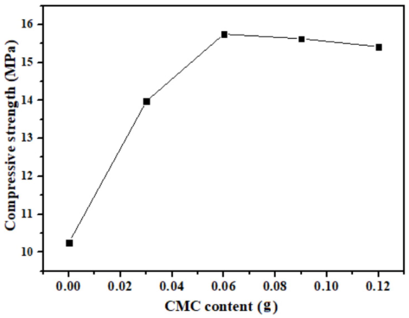
Fig. 2 shows the effect of varying CMC content on the compressive strength of porous ceramics prepared from P1. In the absence of CMC, the porous ceramic exhibits the lowest compressive strength of 10.25 MPa. As the CMC amount increases to 0.06 g, its compressive strength reaches a maximum value of 15.75 MPa. However, further increases in CMC to 0.09 g and 0.12 g result in a decline in strength. This reduction can be attributed to excessive dispersant introducing excessive free polymer chains into the slurry, which increases viscosity and may induce steric hindrance or bridging flocculation. These effects reduce interparticle contact and impede densification [39]. Given that the 0.06 g CMC addition yields the highest compressive strength, this content is selected as the optimal dispersant content for subsequent experiments.
Influence of FAHSs particle size on mechanical properties of porous ceramics
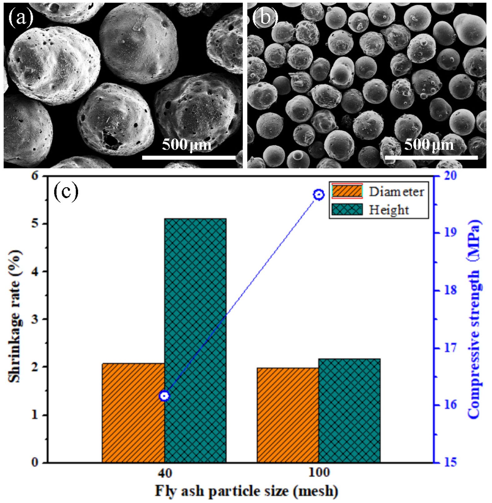
When the particle sizes of FAHSs are different, the compressive strength, diameter and height shrinkage rate of porous ceramics prepared from P1 and P2 are shown in Fig. 3. In Fig. 3a and b, the shapes of the 40 mesh and 100 mesh FAHSs are approximately spherical, with some particles exhibiting rough and porous surfaces. In Fig. 3c, when the particle size of FAHSs is 40 mesh, the diameter and height shrinkage rate shrinkage rate of the porous ceramics prepared from P1 are 2.08% and 5.11%, respectively. When the particle size of FAHSs is 100 mesh, the diameter and height shrinkage rate of porous ceramics prepared from P2 are 1.99% and 2.18%, which is much lower than that of porous ceramics obtained from other methods [40]. Obviously, the shrinkage of porous ceramics in diameter and height direction decreases with the decrease of FAHS particle size. It indicates that with a decrease in particle size, the pore size distribution becomes narrower and the pores are homogenous. Fine-grained particles can decrease the sizes of pores resulting from particle packing [41], this is conducive to the reduction of the sintering shrinkage of samples. In addition, the compressive strength of porous ceramics prepared from P2 is 3.51 MPa higher than that of porous ceramics prepared from P1. It can be seen that porous ceramics with high strength can be prepared using the fine-grained FAHSs, which proves that the reduction of raw material particle size can improve the mechanical properties of porous ceramics [40, 41].
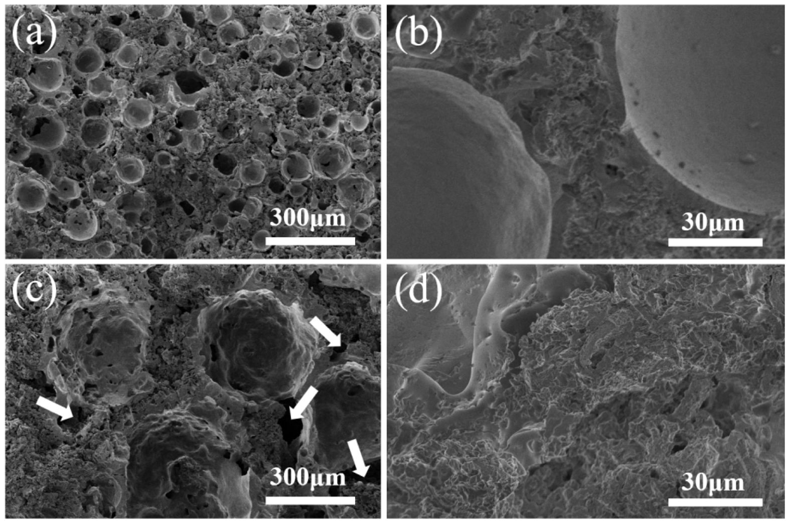
Fig. 4 shows the morphologies of porous ceramics prepared from P1 and P2. When the particle size of FAHSs is 100 mesh, the FAHSs in porous ceramics prepared from P2 are uniformly dispersed, and their hollow structures are intact (Fig. 4a). The pores between the FAHSs are completely filled with diatomite and perlite powder, and the resulting ceramic skeleton presents a porous structure (Fig. 4b), which can provide filtering channels and adsorption sites for porous ceramics in application [42]. Hence an obvious hierarchical pore structure is formed in the porous ceramic. When the particle size of FAHSs is 40 mesh, the dispersion of FAHSs in porous ceramics prepared from P1 is relatively uniform (Fig. 4c). The FAHSs are loosely filled with diatomite and perlite powder, and there are partially unfilled areas (indicated by white arrows). The micropores between the filled particles and on their surfaces are clearly seen (Fig. 4d). According to the results in Fig. 3 and Fig. 4, porous ceramics with uniform structure and high compressive strength can be prepared from P2 with 100 mesh FAHSs as the main raw material.
Influence of slurry composition on mechanical properties of porous ceramics
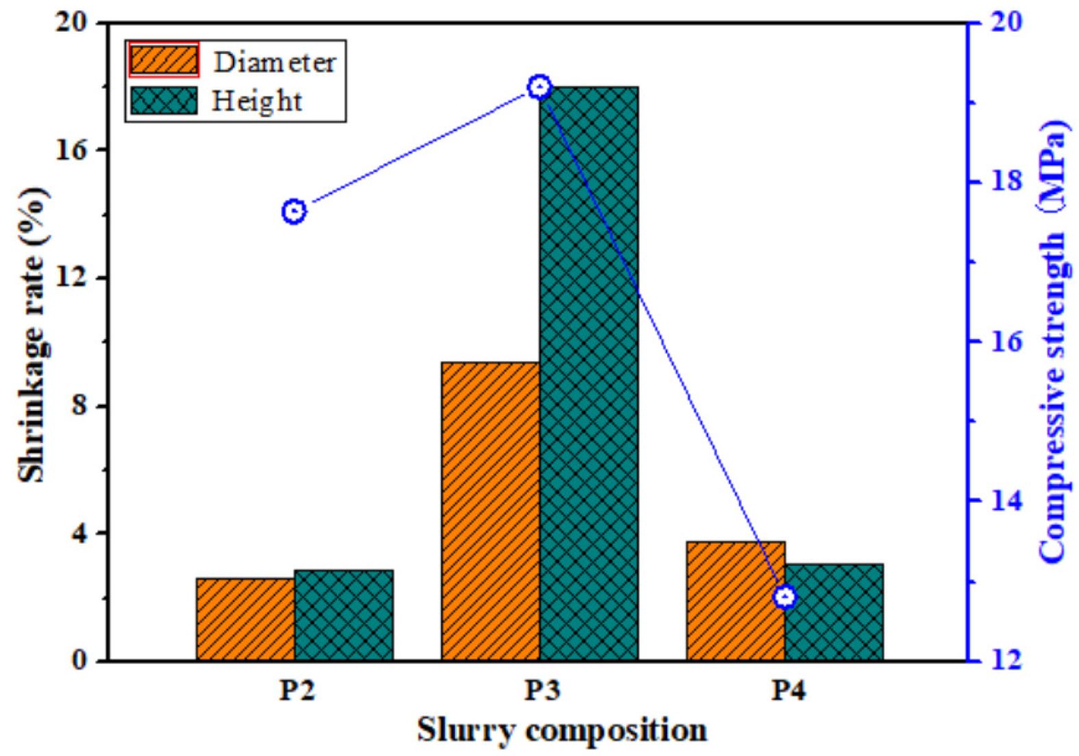
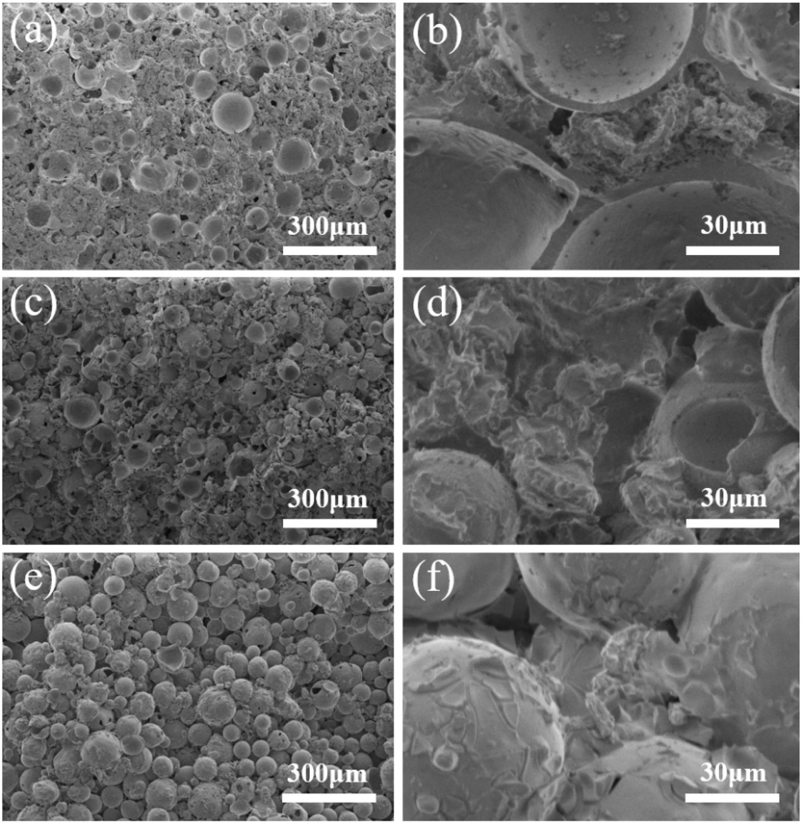
Fig. 5 shows the shrinkage rate and compressive strength of porous ceramics prepared with different slurry composition. When the slurry consists of FAHSs, diatomite and perlite powder, the compressive strength, diameter and height shrinkage rate of the porous ceramics prepared from P2 are 17.64 MPa, 2.62% and 2.86%, respectively. When the slurry composition is FAHSs and perlite powders, the diameter and height shrinkage rate of the porous ceramics prepared from P3 increase to 9.37% and 17.99%, respectively, and their compressive strength increases to 19.2 MPa, which is higher than that of porous ceramics prepared from P2. When the slurry composition is FAHSs and diatomite powder, the diameter and height shrinkage rate of porous ceramics prepared from P4 decrease to 3.74% and 3.02%, respectively, but their compressive strength decreases to 12.81 MPa. It can be seen that the shrinkage of porous ceramics prepared from P2 is smaller, while the compressive strength of porous ceramics prepared from P3 is higher.
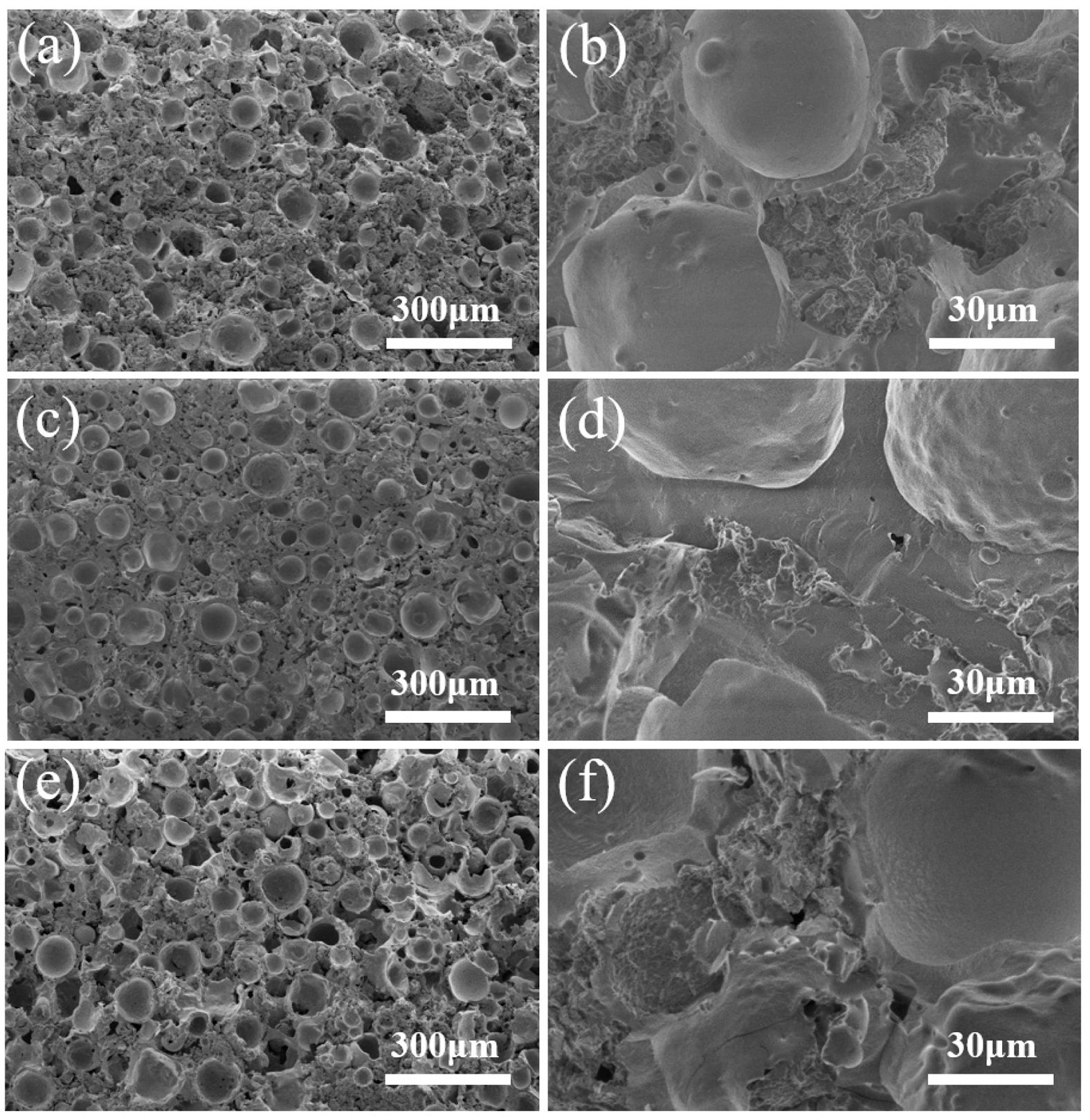
Fig. 6 shows the microstructures of porous ceramics prepared from P2, P3 and P4. The FAHSs in porous ceramics prepared from P2 is uniformly dispersed and their hollow structure is complete. The diatomite and perlite particles are uniformly filled between the FAHSs, the micropores on the particle surface and between the particles are clear and the liquid phase is moderate. Obvious hierarchical pore structure is formed in porous ceramics. In Fig. 6c and d, the FAHSs in porous ceramics prepared from P3 is relatively uniform, but the perlite powders filled between the FAHSs produces too much liquid phase, resulting in their micropores almost disappearing, which is due to the low melting point of expanded perlite (950-1050 ℃) [43, 44]. In the porous ceramics prepared from P4 (Fig. 6(g-h)), diatomite is filled between the uniformly dispersed FAHSs, but the liquid phase between ceramic particles is relatively less. Because the nanopores on the surface and internal hollow structure of diatomite have good adsorption [32, 45, 46], which is not conducive to excessive formation of liquid phase at proper sintering temperature. Therefore, the porous ceramics prepared from P2 have higher compressive strength, lower shrinkage rate and obvious hierarchical pore structure.
Influence of sol addition on mechanical properties of porous ceramics
Fig. 7 shows the microstructures of porous ceramics prepared using different kinds of sols as binders. In the porous ceramics prepared with silica sol as binder (Fig. 7(a-b)), the FAHSs are tightly bonded, and the fracture surface of the FAHSs in porous ceramics is in their middle position. The fracture mechanism changes from fracturing along FAHSs to fracturing across FAHSs with the increase of mechanical strength of FAHS ceramic foams [40]. This further shows that the porous ceramics prepared by silica sol as binder have higher compressive strength. In Fig. 7(c-d), some complete FAHSs in the cross section of porous ceramics prepared with aluminum sol as binder are clearly seen, and the FAHSs are not tightly bonded with the ceramic powder in their gaps. In Fig. 7(e-f), the FAHSs in the section of porous ceramics prepared with aluminum-silica sol as binder are approximately complete spherical, and the pores between FAHSs are large, which indicates that the porous ceramics prepared with aluminum silica sol as binder have poor performance. Therefore, the use of silica sol as a binder is beneficial to the preparation of porous ceramics with high strength.
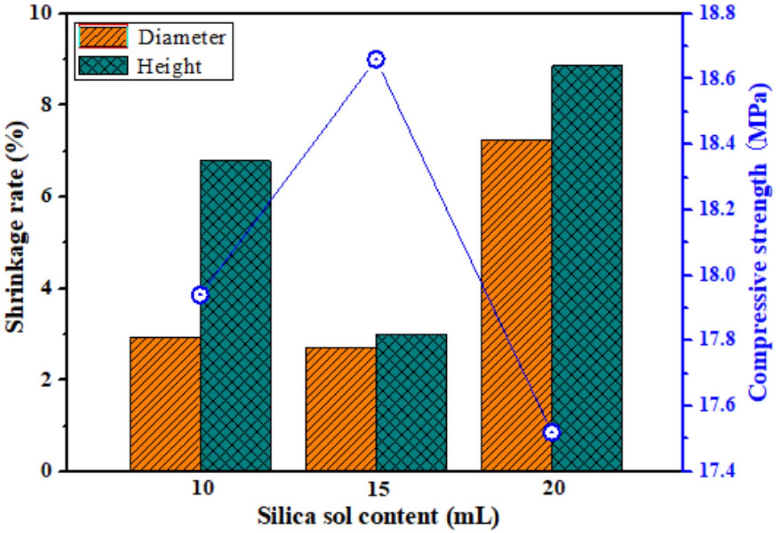
When the amount of silica sol is different, the shrinkage rate and compressive strength of the porous ceramic prepared from P2 are shown in Fig. 8. When the amount of silica sol is 10 mL, the diameter shrinkage rate of the porous ceramic is small (2.94%), but its compressive strength is low (17.94 MPa). Because silica glasses can be prepared from silica sol sintered at 900-950 ℃ [47-50], less amount of silica sol will result in less liquid phase formed by silica sol between ceramic particles, and weak adhesion between particles will result in relatively low compressive strength of porous ceramics. With the increase of silica sol content from 15 to 20 mL, the compressive strength of porous ceramics decreases from 18.66 to 17.52 MPa, and their diameter and height shrinkage rate increase by 4% and 5%, respectively. Therefore, when the amount of silica sol is 15 mL, the prepared porous ceramics have higher compressive strength and lower sintering shrinkage.
Effect of sintering temperature on mechanical properties of porous ceramics
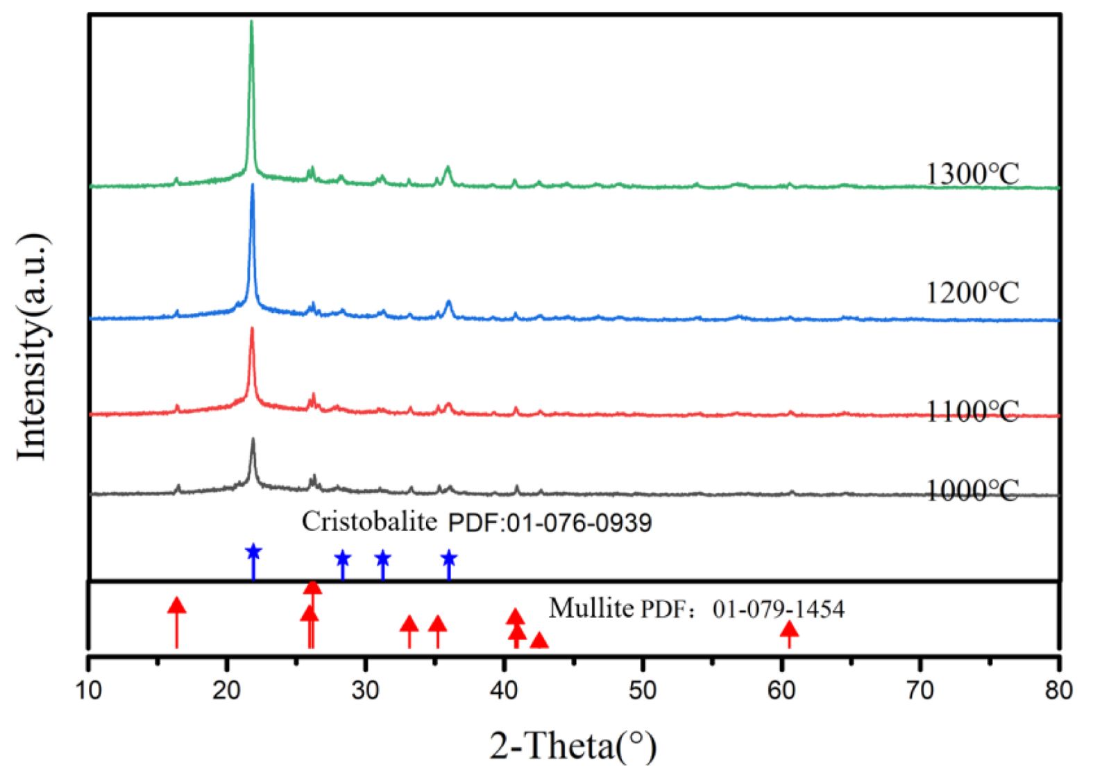
Fig. 9 shows XRD patterns of porous ceramics prepared from P2 at different sintering temperature. The crystalline phase in porous ceramics is mainly cristobalite and a small amount of mullite. The amount of cristobalite increases with the increase of sintering temperature, which suggests that porous silica ceramics can be prepared above 1000 °C.
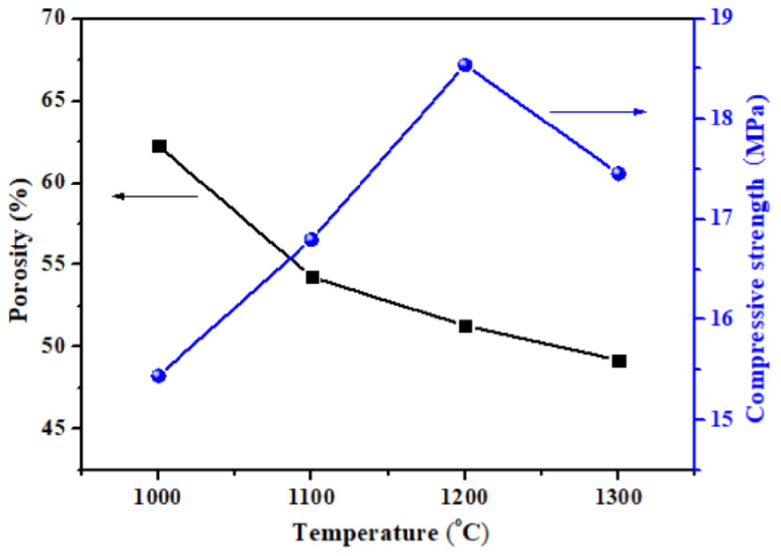
Fig. 10 shows the porosity and compressive strength of porous ceramics prepared from P2 at different sintering temperatures. With the increase of sintering temperature, the porosity of porous ceramics decreases, and their compressive strength first increases rapidly and then decreases. The increased strength was due to the generation of liquid phase and the stronger sintering necks formed in porous ceramics at a higher temperature [42]. When the sintering temperature is 1200 ℃, the compressive strength of the prepared porous ceramic is the highest. It can be seen that the porous ceramic prepared at 1200 °C has high compressive strength (18.54 MPa) and high porosity (51.3%).
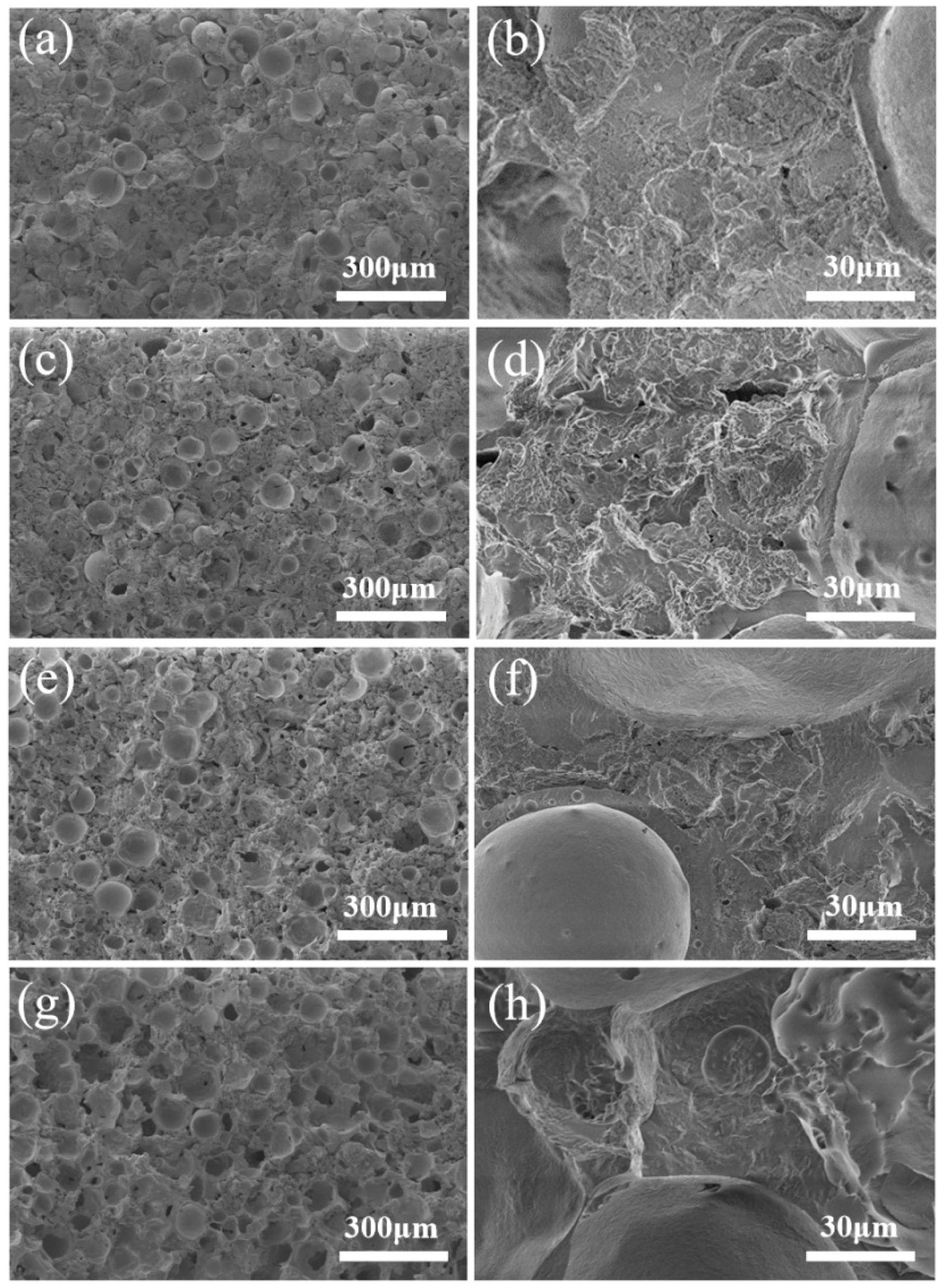
Fig. 11 shows the microstructures of porous ceramics prepared from P2 at different sintering temperature. When the sintering temperature is 1000 ℃, there are some complete FAHSs in the cross section of porous ceramics (Fig. 11a), indicating the formation of weak sintering necks between ceramic particles [36]. Almost no liquid phase is formed in the ceramic powders filled between the FAHSs, and their surface micropores are clearly seen (Fig. 11b). In Fig. 11c-h, when the sintering temperature increases from 1100 to 1300℃, almost no complete FAHSs can be seen in the section of porous ceramics, indicating that the FAHSs are firmly interconnected with the filled powders, which is consistent with the results in the literature [36, 40]. However, when the sintering temperature increases, the liquid phase in the ceramic powder filled between the FAHSs gradually increases. When the sintering temperature is 1300 ℃, too much liquid phase is formed in ceramic powders, which may be the reason for the decrease of compressive strength of porous ceramics.
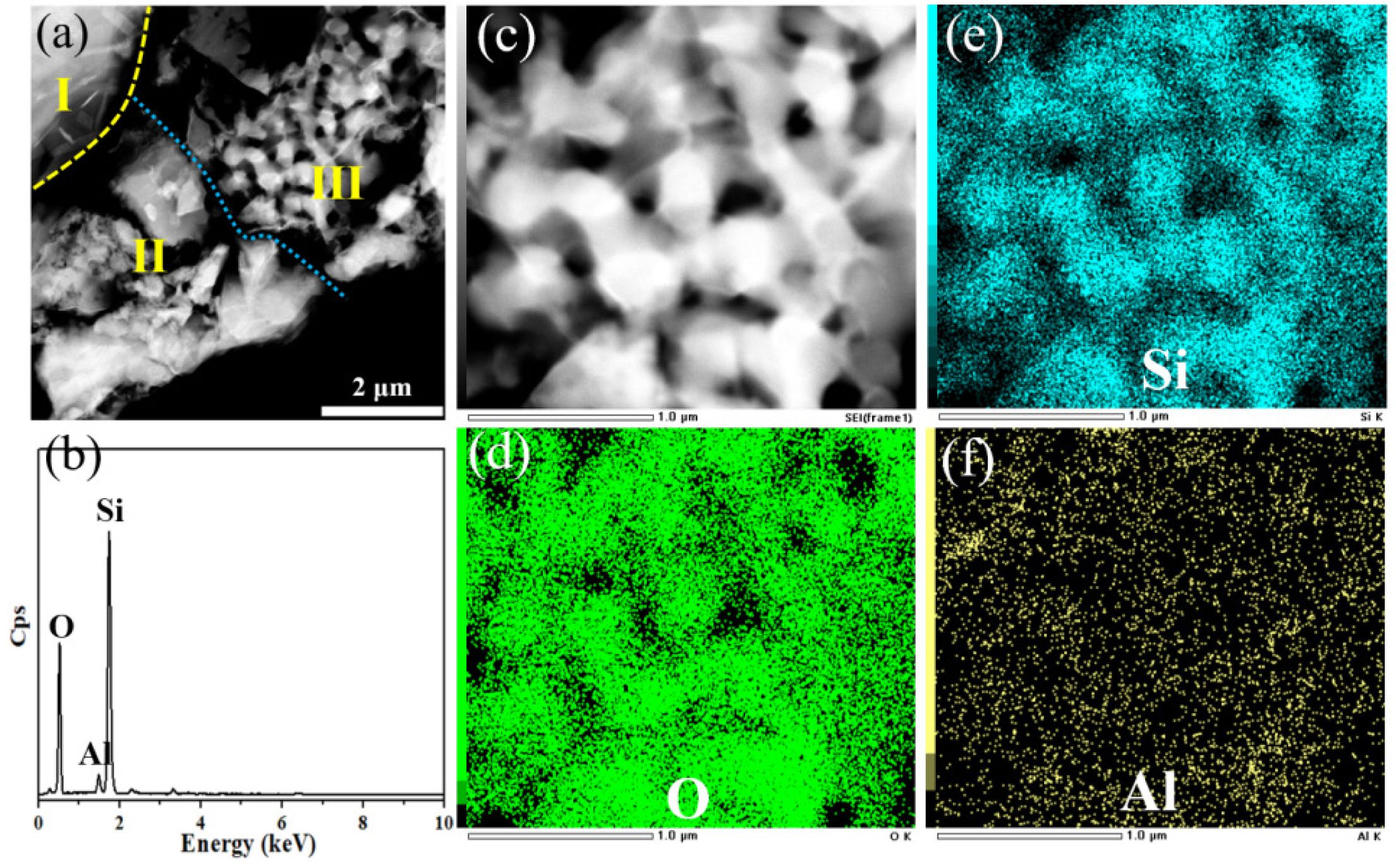
TEM image of the microstructure of porous ceramic prepared from P2 at 1200 °C is shown in Fig. 12a. Area Ⅰ exhibits the edge of a single FAHS, and the ceramic powders in area Ⅱ and area Ⅲ should be perlite and diatomite respectively according to the reported results [45, 51]. These two regions still have the hierarchical pore structure, and Si, Al and O as the main constituent elements are confirmed to exist in them (Fig. 12b). As shown in the partial morphology and corresponding EDX element mappings of area Ⅲ (Fig. 12c-f), the nanopores of diatomite mainly composed of Si and O elements still exist after sintering, indicating that the hierarchically porous silica ceramics are prepared at 1200 °C.
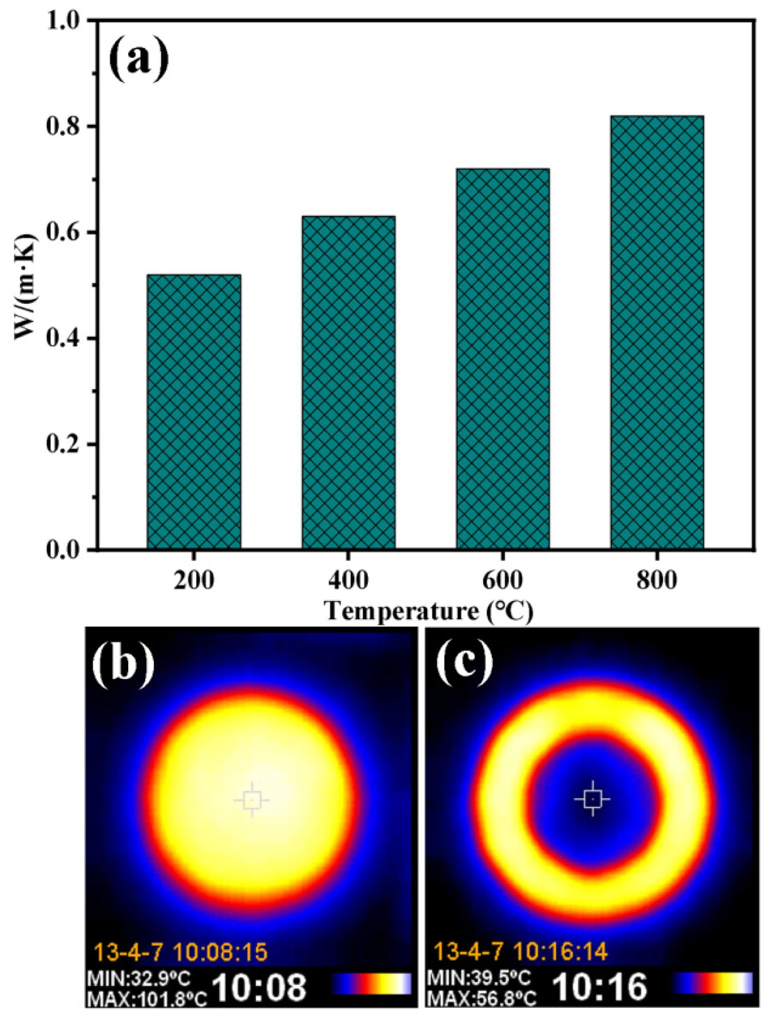
Fig. 13 shows the variation of thermal conductivity of porous ceramics prepared using P2 at 1200 °C as a function of temperature. When the test temperature increases from 200 to 800 °C, the thermal conductivity of the samples is 0.52-0.82W/m·K, and their thermal conductivity increase slowly with the increase of temperature. When the sample is heated on the test plate at 102 ℃ for 300 s, its upper surface temperature is only 44 ℃, which indicates that it has good thermal insulation performance.
|
Fig. 1 Optical photos of the surface and cross section of porous ceramics prepared from P1 with different dispersants: (a, b) CMC, (c, d) sodium polyacrylate and (e, f) polyethylene glycol. |
|
Fig. 2 Compressive strength of porous ceramics prepared from P1 with different CMC content. |
|
Fig. 3 SEM images of FAHSs with particle sizes of (a) 40 mesh and (b) 100 mesh; (c) compressive strength, diameter and height shrinkage rate of porous ceramics prepared from P1 and P2 with different particle sizes of FAHSs. |
|
Fig. 4 SEM images of porous ceramics prepared from (a, b) P1 and (c, d) P2. |
|
Fig. 5 Compressive strength and shrinkage rate of porous ceramics prepared with different slurry composition. |
|
Fig. 6 SEM images of porous ceramics prepared from (a, b) P2, (c, d) P3 and (e, f) P4. |
|
Fig. 7 SEM images of porous ceramics prepared using different kinds of sols as binders: (a, b) silica sol, (c, d) aluminum sol and (e, f) aluminum-silica sol. |
|
Fig. 8 Shrinkage rate and compressive strength of the porous ceramic prepared from P2 with different silica sol content. |
|
Fig. 9 XRD patterns of porous ceramics prepared at different sintering temperature. |
|
Fig. 10 Porosity and compressive strength of porous ceramics prepared from P2 at different sintering temperature. |
|
Fig. 11 SEM images of porous ceramics prepared from P2 at different sintering temperature: (a, b) 1000; (c, d) 1100; (e, f) 1200 and (g, h) 1300 °C. |
|
Fig. 12 (a) TEM image of microstructure of porous ceramic prepared from P2 at 1200 °C; (b) EDX spectrum of area Ⅱ and area Ⅲ and (c-f) element mapping of area Ⅲ in (a). |
|
Fig. 13 (a) Variation of thermal conductivity with temperature for porous ceramics prepared using P2 at 1200 °C; (b) Infrared images of the heated test plate and a sample after insulating against it. |
Hierarchically porous SiO2 ceramics were prepared by gel casting using FAHSs, diatomite and perlite as main raw materials. The dispersion of the slurry with CMC as dispersant is better than that of sodium polyacrylate and polyethylene glycol. The porous ceramics prepared using fine-grained (100 mesh) FAHSs as the main raw material have lower sintering shrinkage and higher compressive strength. When silica sol is used as binder, the microstructure uniformity of porous ceramics is better than that of aluminum sol and aluminum-silica sol. When the amount of silica sol is 15 mL, the addition of CMC is 0.06 g and the sintering temperature is 1200 ℃, the porous ceramics prepared from P2 have the uniform dispersion of FAHSs, strong bonding between ceramic particles and obvious hierarchical pore structure. The compressive strength of the prepared porous ceramics is 18.54 MPa, and their diameter shrinkage and height shrinkage are 2.62% and 2.86%, respectively. This paper provides a feasible method for simply preparing porous ceramics with hierarchical pore structures and solving the pollution of FAHSs. In summary, this gel casting method not only offers an innovative pathway for waste valorization, but also produces porous silica ceramics with excellent comprehensive properties, presenting significant potential for industrial applications in thermal insulation, filtration, catalyst supports, and lightweight structural materials.
The authors are thankful for the financial support provided by the Science and Technology Project of Pingxiang, China (No. 2024C0106, No. 2024C0103), and the Technology Development Project of PipeChina Institute of Science and Technology (Grant No. ZYZL-DTXNY-202204).
- 1. T. Ohji and M. Fukushima, Int. Mater. Rev. 57 (2012) 115-131.
-

- 2. Y.W. Kim, S.H. Kim, I.H. Song, H.D. Kim, and C.B. Park, J. Am. Ceram. Soc. 88 (2005) 2949-2951.
-
- 3. D. Suastiyanti, M. Wijaya, and B.G. Pandita, J. Ceram. Process. Res. 25[2] (2024) 261-267.
-
- 4. B. Román-Manso, J. Muth, L.J. Gibson, W. Ruettinger, and J.A. Lewis, ACS Appl. Mater. Inter. 13 (2021) 8976-8984.
-
- 5. C.B. Huo, X.Y. Tian, Y. Nan, and D.C. Li, J. Eur. Ceram. Soc. 40 (2020) 4253-4264.
-
- 6. T.J. Kuo, L.M. Rueschhoff, M.B. Dickerson, T.A. Patel, and K.T. Faber, Scripta. Mater. 191 (2021) 204-209.
-
- 7. R.B. Zhang, C.S. Ye, and Y.Y. Zhang, Appl. Surf. Sci. 360 (2016) 1036-1040.
-
- 8. H.B. Wu, Y.S. Li, S. Yun, X.J. Liu, Z.R. Huang, and D.L. Jiang, J. Alloy. Compd. 732 (2018) 547-554.
-
- 9. H. Zhang, P.D.A. Nunes, M. Wilhelm, and K. Rezwan, J. Eur. Ceram. Soc. 36 (2016) 51-58.
-
- 10. W.L. Huo, X.Y. Zhang, S.Y. Hou, Y.G. Chen, Y.L. Wang, and J.L. Yang, J. Am. Ceram. Soc. 102 (2019) 3753-3762.
-
- 11. V. Naglieri and P. Colombo, J. Eur. Ceram. Soc. 37 (2017) 2559-2568.
-
- 12. W.L. Huo, X.Y. Zhang, K. Gan, H.Z. Li, S. Yan, Y.G. Chen, and J.L. Yang, Chem. Eng. J. 360 (2019) 1459-1467.
-
- 13. K. Mohanta, A. Kumar, O. Parkash, and D. Kumar, J. Am. Ceram. Soc. 97 (2014) 1708-1719.
-
- 14. H. Liu, L.Y. Li, J.T. Li, A.R. Guo, X.X. Hu, and H.Y. Du, Ceram. Int. 47 (2021) 8593-8600.
-
- 15. L. Andersson and L. Bergström, J. Eur. Ceram. Soc. 28[15] (2008) 2815-2821.
-
- 16. R.Y. Chen, W.B. Jia, D.Q. Hei, and Y.F. Wang, Ceram. Int. 44 (2018) 21478-21485.
-
- 17. X. Liang, Y.W. Li, S.B. Sang, Q.H. Wang, Z. He, and B.W. Li, Ceram. Int. 46 (2020) 11246-11254.
-
- 18. C.R. Bowen and T. Thomas, Ceram. Int. 41[9] (2015) 12178-12185.
-
- 19. F. Darus, R.M. Isa, N. Mamat, and M. Jaafar, Ceram. Int. 44[15] (2018) 18400-18407.
-
- 20. A. Fadli and I. Sopyan. J. Porous Mater. 18 (2011) 195-203.
-
- 21. J.J. Liu, B. Ren, Y.L. Wang, Y.J. Lu, L. Wang, Y.G. Chen, J.L. Yang, and Y. Huang, Chem. Eng. J. 362 (2019) 504-512.
-
- 22. A.R. Studart, U.T. Gonzenbach, E. Tervoort, and L. Gauckler, J. Am. Ceram. Soc. 89 (2006) 1771-1789.
-
- 23. E.C. Hammel, O.L.R. Ighodaro, and O.I. Okoli, Ceram. Int. 40 (2014) 15351-15370.
-
- 24. T.T. Dele-Afolabi, M.A.A. Hanim, M. Norkhairunnisa, S. Sobri, and R. Calin, Ceram. Int. 43 (2017) 1633-1649.
-
- 25. S.S. Liu, M. Li, J.M. Wu, A.N. Chen, Y.S. Shi, and C.H. Li, Ceram. Int. 46 (2020) 4240-4247.
-
- 26. J.M. Wu, X.Y. Zhang, and J.L. Yang, J. Eur. Ceram. Soc. 34 (2014) 1089-1096.
-
- 27. F. Qi, X.X. Xu, J. Xu, Y.L. Wang, and J.L. Yang, J. Am. Ceram. Soc. 97 (2014) 3341-3347.
-
- 28. Y.J. Xue, R.M. Liu, S.T. Xie, R.L. Liu, W. Jing, J.C. Liu, and A.R. Guo, Ceram. Int. 45 (2019) 2612-2620.
-
- 29. W.L. Huo, X.Y. Zhang, Z.L. Hu, Y.G. Chen, Y.L. Wang, and J.L. Yang, J. Am. Ceram. Soc. 102 (2019) 955-961.
-
- 30. D. Das, K. Nijhuma, A.M. Gabriel, G.P.F. Daniel, and D.d.M.I. Murilo, J. Eur. Ceram. Soc. 40 (2020) 2163-2172.
-
- 31. T.F. Choo, M.A. Mohd Salleh, K.Y. Kok, and K.A. Matori, Ceram. Int. 45 (2019) 21827-21834.
-
- 32. K.L. Lin and J.C. Chang, Environ. Prog. Sustain. 32 (2013) 25-34.
-
- 33. Y.B. Zong, Q.L. Wan, and D.Q. Cang, Ceram. Int. 45 (2019) 22445-22451.
-
- 34. S. Chen, W.H. Cai, J.M. Wu, Y.X. Ma, C.H. Li, Y.S. Shi, C.Z. Yan, Y.J. Wang, and H.X. Zhang, Ceram. Int. 46 (2020) 17508-17513.
-
- 35. Y. Luo, S.L. Zheng, S.H. Ma, C.L. Liu, and X.H. Wang, Constr. Build. Mater. 163 (2018) 529-538.
-
- 36. A.N. Chen, M. Li, J. Xu, C.H. Lou, J.M. Wu, L.J. Cheng, Y.S. Shi, and C.H. Li, J. Eur. Ceram. Soc. 38 (2018) 4553-4559.
-
- 37. J.J. Ding, F. Ye, Q. Liu, C.P. Yang, and Y. Gao, Ceram. Int. 45 (2019) 10126-10132.
-
- 38. W. Wan, J. Yang, J.Z. Zeng, L.C. Yao, and T. Qiu, Ceram. Int. 40 (2014) 1735-1740.
-
- 39. L.Y. Wang, L.Q. An, J. Zhao, S.Z. Shimai, X.J. Mao, J. Zhang, J. Liu, and S.W. Wang, J. Adv. Ceram. 10 (2021) 852-859.
-
- 40. W.L. Huo, X.Y. Zhang, Y.G. Chen, Y.J. Lu, J.J. Liu, S. Yan, J.M. Wu, and J.L. Yang, J. Eur. Ceram. Soc. 38 (2018) 2035-2042.
-
- 41. W. Yan, N. Li, Y.Y. Li, G.P. Liu, B.Q. Han, and J.L. Xu, B. Mater. Sci. 34 (2011) 1109-1112.
-
- 42. F. Jiang, L.L. Zhang, Z. Jiang, C. Li, D.Q. Cang, X.L. Liu, Y.M. Xuan, and Y.L. Ding, Ceram. Int. 45 (2019) 6085-6092.
-
- 43. W. Pichór, A. Janiec, Ceram. Int. 35 (2009) 527-530.
-
- 44. O.A. Al-Harbi, C. Özgür, and M.M. Khan, J. Ceram. Process. Res. 17 (2016) 275-280.
-
- 45. L.P. Hao, W.Y. Gao, S. Yan, M.H. Niu, G.S. Liu, and H.S. Hao, Mater. Chem. Phys. 235 (2019) 121741.
-
- 46. Y.N. Lee , S.H. Ahn, H. Nam, and K.W. Nam, J. Ceram. Process. Res. 19 (2018) 467-471.
-
- 47. Y.H. Chen, X. Hu, T. Lin, Y. Li, and Z.Y. Ling, Ceram. Int. 47 (2021) 19340-19345.
-
- 48. M.S. Kwon, S.G. Lee, and K.M. Kim, J. Ceram. Process. Res. 19 (2018) 321-326.
-
- 49. Y. Cao, Y.M. Li, K. Li, C.M. Zou, J.L. Hu, and J. Wen, J. Ceram. Process. Res. 26 (2025) 807-814.
-
- 50. X.L. Shi, H. Li, Y.Z. Huang, and P. Colombo, J. Ceram. Process. Res. 26 (2025) 1111-1121.
-
- 51. W. Wheelwright, R.P. Cooney, S. Ray, Z. Zujovic, and K.D. Silva, Ceram. Int. 43 (2017) 11495-11504.
-
 This Article
-
2026; 27(1): 71-78
Published on Feb 28, 2026
- 10.36410/jcpr.2026.27.1.71
- Received on Aug 24, 2025
- Revised on Nov 30, 2025
- Accepted on Dec 23, 2025
Services
- Abstract
introduction
experimental
results and discussion
conclusions
- Acknowledgements
- References
- Full Text PDF
Shared
Correspondence to
- Xinshuang Guo and Haifeng Guo
-
Engineering & Technology Research Center for Environmental Protection Materials and Equipment of Jiangxi Province, College of Materials and Chemical Engineering, Pingxiang University, Pingxiang 337055, PR China
Tel : +86 799 6682008 Fax: +86 799 6682008 - E-mail: xsguo12b@alum.imr.ac.cn (Xinshuang Guo), guohaifen
Clean-Energy Research Institute(CRI), Hanyang University, 222, Wangsimni-ro, Seongdong-gu, Seoul, 04763, Korea
E-mail: jcpr@hanyang.ac.kr