


- Study on inner cylindrical surface quality of zirconia ceramic sleeves ground by Narrow-Grit-Face-Grinding-Wheels
Yong Shaa,b,*, Hao Zhanga,b,*, Xiaogang Zhanga and Di Cuia
aSchool of Mechanical Engineering, Gansu Vocational University of Industry Technology, Tianshui 741000, China
bGansu Provincial 3D Printing Industry Technology Center, Tianshui 741000, ChinaThis article is an open access article distributed under the terms of the Creative Commons Attribution Non-Commercial License (http://creativecommons.org/licenses/by-nc/4.0) which permits unrestricted non-commercial use, distribution, and reproduction in any medium, provided the original work is properly cited.
Due to the brittle and hard nature of engineering ceramics, achieving efficient, precise, and low-cost machining of ceramic rings has long been a challenging issue. Taking zirconia ceramic rings as an example, this paper explores the material removal mechanism of engineering ceramics, aiming to achieve efficient and precise internal grinding of wide-gap rings using conventional narrow-grit-face-grinding-wheels. Subsequently, a 3D morphology model for material removal simulation and a kinematic model of the contact points between the grinding wheel and the workpiece were established, and the surface roughness was calculated. The results show that the final surface quality is closely related to the surface quality of a single grinding pass, and the simulation results generally agree with the trend of the experimental results. Increasing the workpiece rotation speed, reducing the abrasive size, and decreasing the grinding wheel feed rate are beneficial for improving the surface quality of zirconia ceramic rings after machining. The research findings provide a theoretical basis for the application of narrow-grit-face-grinding-wheels in the internal grinding of wide-gap ring parts and offer theoretical guidance for subsequent process optimization.
Keywords: Engineering ceramics, Removal model, Kinematic model, Surface quality.
Engineering ceramics are widely used in various industries due to their superior properties, such as high hardness, high temperature resistance, corrosion resistance, excellent wear resistance, and low thermal expansion coefficient. However, their inherent high hardness and brittleness make them extremely difficult to machine. Grinding has thus become a critical processing method in the field of engineering ceramics.
Although the processing efficiency of engineering ceramics has been improved to a certain extent by optimizing processing parameters and enhancing machine tool precision [1], ensuring surface quality while achieving high-efficiency machining remains a key focus of research [2-4]. In the manufacturing of ceramic bearings, centerless grinding has been widely applied in the external cylindrical processing of bearing rings, enabling mass production [5-7]. Nevertheless, achieving the efficient and precise internal cylindrical machining of ring workpieces remains a significant challenge.
In the field of machining brittle and hard materials, researchers have contributed to improving the machined surface quality by studying material removal mechanisms and predicting surface roughness [8, 9]. These methods describe the material removal mechanisms and lay a foundation for subsequent research. Although the ring is a circular component in terms of its macrostructure, the material removal at the microscale can still be equivalent to that of a flat surface.
Reference [10] investigates the influence of machining parameters on the surface quality of steel bearing rings. For steel bearing rings, turning is the machining method, with some studies also involving internal cylindrical grinding of steel bearing rings. However, research on the internal machining of ceramic rings is extremely limited. Although [11] and [12] report on about the internal cylindrical grinding of silicon nitride ceramic rings, elaborating on the impact of grinding parameters on internal surface quality, their research remains at the experimental stage and does not provide a detailed description of the formation mechanism of surface morphology during the machining process.
To date, no research has explored the influence of narrow-grit-face-grinding-wheels on surface quality when grinding ceramic rings of different widths during the internal cylindrical grinding process. Taking zirconia ceramic rings as the research object, this paper establishes a 3D surface model to observe the removal mechanism based on the grinding mechanism of brittle and hard materials, and constructs a kinematic model of narrow-grit-face-grinding-wheels in ring processing. This enables the screening of optimal parameter combinations, which is of great significance for the wide application of ordinary grinding wheels in the internal cylindrical grinding of rings and can significantly reduce the processing costs caused by customized grinding wheels.
For the inner circle machining of zirconia sleeves using narrow-grit-face-grinding-wheels, the research mainly focuses on two aspects: the influence of machining parameters on the surface quality of the sleeve inner circle and the impact of grinding wheel motion parameters on machining uniformity. Therefore, in the modeling process, the key tasks are the modeling of the machined surface topography and the modeling of the machining trajectory on the inner circle surface of the sleeve.
Modeling of material removal
The machining process of engineering ceramics is mainly characterized by the diamond abrasives distributed on the surface of the grinding wheel, which scratch the workpiece surface during machining and remove the material from the workpiece surface. Therefore, the distribution of abrasives on the grinding wheel surface also needs to be considered.
In the spatial surface distribution, assuming the density of abrasives is ρ, the total number of abrasives involved in the surface can be expressed as:

Where Lx is the length of the workpiece surface, Ly is the surface width, and d is the grain diameter.
According to the research by Zhou et al. [13], the abrasive protrusion height on the grinding wheel surface follows a normal distribution. Therefore, it is assumed that the abrasive protrusion height conforms to a normal distribution, and its distribution function can be expressed as:
where μ0 is the mean of the normal distribution, and σ0 is the standard deviation of the normal distribution. Statistical analysis was conducted on the abrasive grains on the grinding wheel surface, and the average protrusion height of these abrasive grains is approximately 1/4 of their diameter, σ0 = dm-dp/3, For abrasives with a grit size of Q, the maximum abrasive diameter dm, average abrasive diameter dp, and the expression for the average spacing between all adjacent contacting abrasives Δ on the grinding wheel surface can be described by the following expressions, respectively:
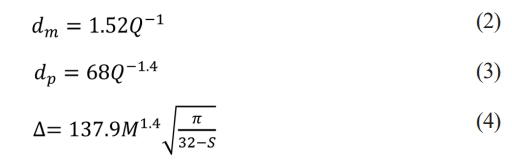
where: S is the grinding wheel structure parameter, which can be expressed as: S = 32 - (Vg/2) ; and Vg is the abrasive concentration of the grinding wheel.
The removal mechanism for describing brittle and hard materials mainly includes the indentation fracture mechanics model and the abrasive cutting model, as shown in Fig. 1.
Since the tip of the abrasive can be regarded as a sphere, according to Hertzian contact theory, the contact radius with the material can be expressed as:
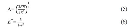
Where F is the normal load of a single abrasive grain, R is the spherical radius of the abrasive contact area, E is the elastic modulus, and ν is Poisson's ratio.
The peak value of the contact pressure can be expressed as:
When the peak value of the contact pressure is equal to the yield strength of the workpiece material, plastic deformation occurs during the machining process, that is:

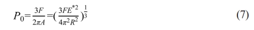
By combining expressions (7) and (8), the expression for the critical depth of cut for plasticity can be obtained as:
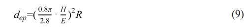
where H is the material hardness;
However, during the machining process, brittle fracture always accompanies plastic material removal, and this characteristic has been confirmed by various studies [14][15]. Based on Griffith's classic theory describing the fracture behavior of brittle materials, crack propagation occurs when the strain energy release rate exceeds twice the surface energy. Therefore, the critical depth for brittle fracture can be expressed as:
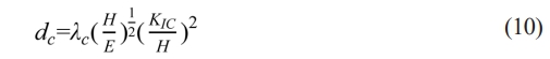
where λc=8.7.
In the above modeling process, discussions have been conducted on both the critical depth of cut for plasticity and brittleness generated when abrasives machine the workpiece. However, due to the irregular distribution of abrasives on the grinding wheel surface—including variations in abrasive protrusion height on the grinding wheel—such morphological characteristics will cause the cutting depth of abrasives to change with the protrusion height of the abrasives during the grinding wheel's machining of the workpiece surface.
In response to the above situation, one scenario is that the material removal process by the abrasive is dominated by the spherical tip of the abrasive, corresponding to a shallow contact area; the other is dominated by the conical part of the abrasive, corresponding to a deep contact area.
For the shallow contact area:
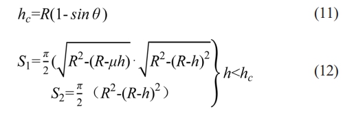
Where S1 is the elastic contact area, S2 is the plastic contact area, h is the actual cutting depth of the abrasive, m is the elastic recovery rate, hc is the critical depth defining the shallow and deep contact areas, and θ is the half-cone angle of the abrasive tip.
For the deep contact area:

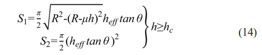
Where heff is the effective contact height.
The relationship between grinding depth and abrasive cutting depth can be expressed as:

where 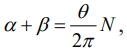 α and β are coefficients for abrasives in shallow and deep contact, θ is the rotation angle of the grinding wheel when the grinding depth is reached, which is positively correlated with the rotational speed of the grinding wheel.
The normal forces generated in different contact areas can be expressed by the following formulas, and the average contact pressure is expressed as:
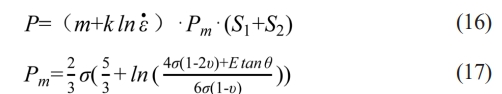
Where m, k is a dimensionless constant and is the strain rate. Studies by C. Gauthier and Pelletier [16, 17] have shown that m and k depend on the local friction coefficient.
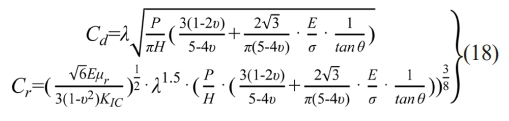
During the material removal process, different abrasives may exhibit different material removal modes at the same time, which can be categorized into material removal caused by the propagation of lateral cracks and longitudinal cracks. For brittle and hard materials, models and expressions describing lateral and longitudinal cracks have been studied [18]:
Modeling of machining trajectories
Due to the diversity of application scenarios, workpieces need to be adapted to their specific application environments, resulting in varying dimensions. Taking bearings as an example, different types of bearings have different ring sizes. However, matching a grinding wheel of the same size to each workpiece size is not a straightforward task and would lead to excessively high processing costs. Therefore, For the inner circle machining of zirconia sleeves using narrow-grit-face-grinding-wheels, are used for workpieces of various sizes to reduce processing costs.
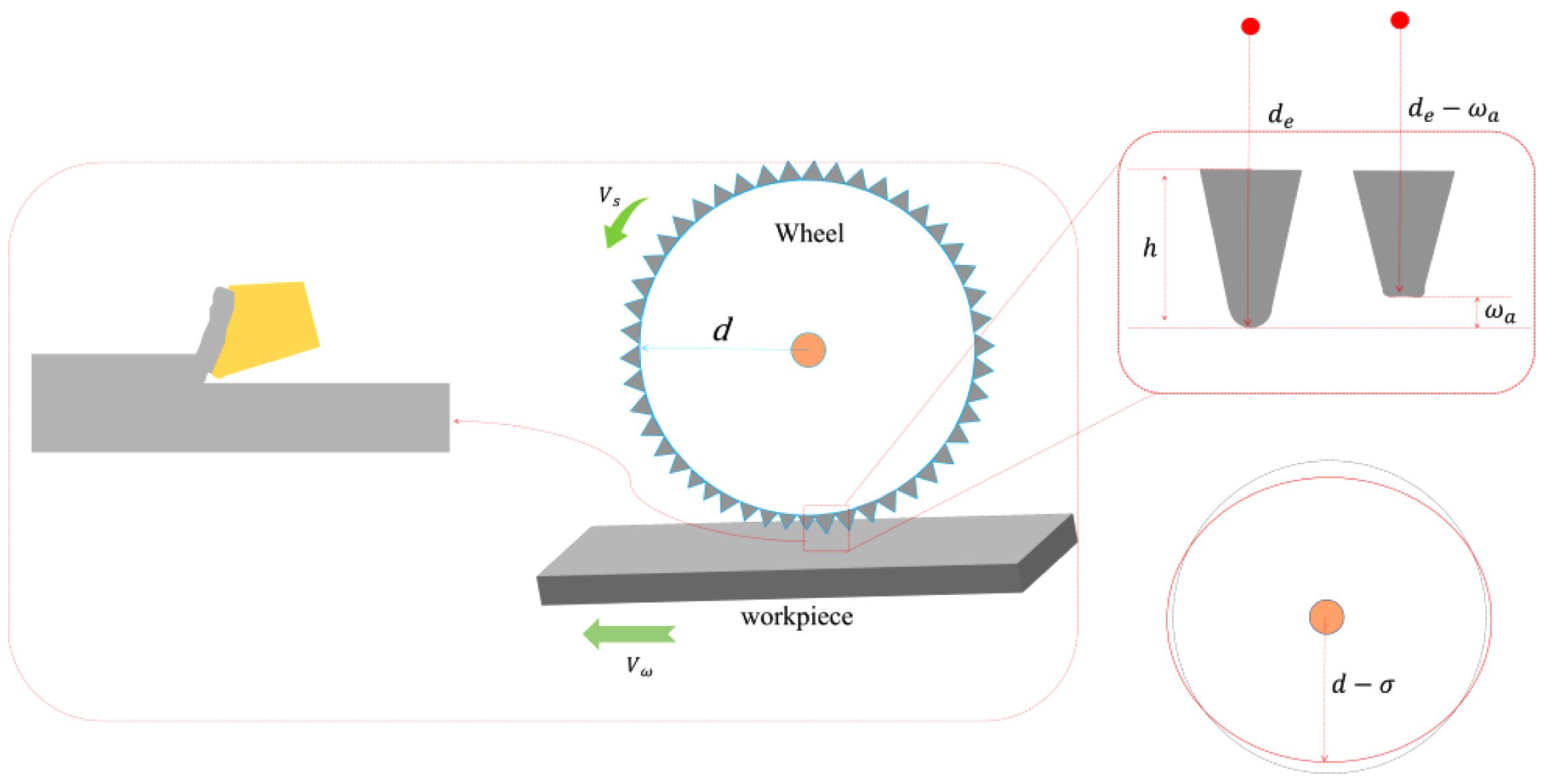
The oscillation of For the inner circle machining of zirconia sleeves using narrow-grit-face-grinding-wheels, is crucial for enabling the machining process to cover the inner circular surface of the workpiece. As can be seen from Fig. 2, there are only two factors affecting the motion trajectory of the grinding wheel on the inner circular surface of the workpiece:
1. Workpiece rotation speed;
2. Grinding wheel oscillation speed.
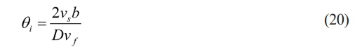
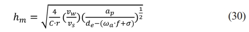
It is necessary to study the machining trajectory of the inner circular surface of the workpiece machined with a narrow-grit-face-grinding-wheel, to determine whether the machining process can completely cover the inner circular surface and achieve the purpose of material removal. Therefore, it is essential to establish the dynamic equation of the machining process. The feed motion is simplified: the grinding wheel feeds once after completing 1/2 oscillation. The single grinding depth can be calculated by the following formula:
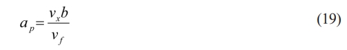
Then the angle rotated by the workpiece when the grinding wheel completes 1/2 oscillation can be expressed as:
As shown in Fig. 2, a coordinate system is established with the center of the workpiece's end face circle as the origin. The contact arc surface between the grinding wheel and the workpiece is simplified to a contact point, and the coordinates of the contact point at different times can be expressed as:
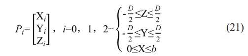
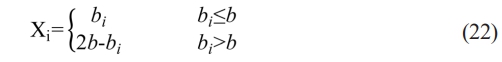
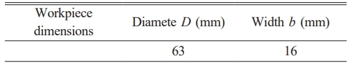
Where i is the corresponding sampling point, D is the workpiece diameter, and b is the workpiece width. The contact point between the grinding wheel and the workpiece must cover the inner surface of the workpiece throughout the machining process. Therefore, in addition to its own rotation, the movement of the grinding wheel should involve a reciprocating periodic motion along the workpiece width direction (the z-axis direction). In other words, when the grinding wheel oscillates once, the stroke length is 2b, which can be expressed as:
The workpiece performs a rotational motion around its center, which is described as rotating around the X-axis. After the contact point P rotates by an angle around the X-axis:
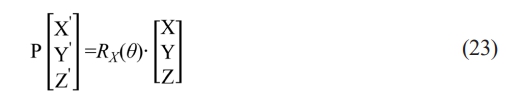
Where: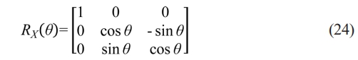
The motion is discretized and sampled, and the three-dimensional coordinates of each sampling point are given by the equation: The sampling time is 0.01s.
Evaluation of Machining Trajectory Uniformity
According to the research by Yang et al. [19], the quantitative evaluation method for the uniformity of machining trajectories on cylindrical surfaces is specified as follows:
(1) The machined cylindrical surface is unfolded and divided into several tiny unit rectangles.
(2) The ratio of the trajectory in the i-th unit to the total trajectory length of the entire cylindrical surface is defined as ri. For ease of reading, it is scaled up, and its expression is given by:
where: li is the trajectory length of the i-th unit, and l is the total length of the machining trajectory on the entire cylindrical surface.
|
Fig. 1 Schematic diagram of material removal dimensions caused by crack propagation. |
|
Fig. 2 Schematic diagram of the motion of the grinding wheel oscillation contact. |
Setup of cutting simulation model and parameters
Machining is a complex coupled process. The distribution and protrusion height of abrasive grains affect the material removal process and also influence the surface quality of the machined workpiece. Using Python, generate N values following a normal distribution with mean 0 and standard deviation 1, denoted as Ci(1, 2, ..., N). Then, the protrusion height of a random abrasive grain is hi = σ0Ci + kμ0, where k is the percentage coefficient of the abrasive grain relative to the surface height of the grinding wheel. The radius of the circle for the i-th protruding abrasive grain is expressed as: ri = R + hi. Abrasives follow a uniform distribution in the width direction of the grinding wheel surface [20], which can be expressed as:
The elastic recovery rate of the material can lead to a significant increase in the contact force between abrasive grains and the workpiece, thereby causing a significant increase in the size of cracks and chipping edges resulting from brittle removal [21, 22]. Therefore, on the basis of considering the random distribution of abrasive grains, strain rate, elastic recovery, and brittle-plastic transition are additionally incorporated. the model is divided into M×N×Z grids, with model dimensions of Lx=1000 μm, Ly=1000 μm and Lz=20 μm respectively, and the grid size is 0.01 μm [18].
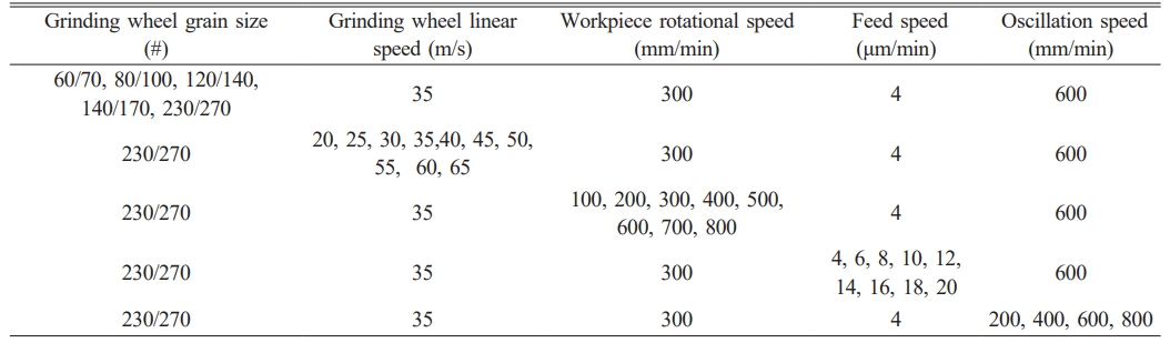
To simplify the calculation process, machining heat and grinding wheel deformation are not considered. The simulation parameters are set as shown in Table 1.
Discussion on Differences between Simulation and Experiment
Due to the randomness of abrasive machining on the grinding wheel surface during the grinding process, it is impossible to fully interpret the grinding process, which further leads to difficulties in modeling and enormous computational demands.Moreover, Thus, assumptions are generally made in the process of modeling and simulation [18, 23]:
1. assuming no change in abrasive shape (abrasives are rigid bodies with no wear);
2. neglecting grinding wheel deformation, among other factors.
3. Do not consider machining heat.
However, under low material removal rates in grinding, the grinding fluid can carry away most of the heat [24]. Studies by Stefan et al. [25] have shown that water-based emulsion grinding fluid can reduce the machined surface temperature by 40%. In the actual machining process, the grinding fluid provides an effective cooling effect, so the grinding thermal effect will not have a critical impact on the machined surface. Therefore, the effects of abrasive flattening and grinding wheel elastic deformation during the grinding process on the surface roughness in practical machining are discussed.The grinding process is shown in Fig. 3.
During the grinding process, the expression relating the wear amount of the abrasive grains per revolution of the grinding wheel to the grinding parameters is [26]:
The Biffano model [27] is used to define the critical chip thickness. Established based on indentation fracture mechanics, this model has the following expression:
The maximum undeformed chip thickness in macro cutting is usually compared with the estimated cutting thickness from the Bifano model to determine the macro ductile grinding of brittle materials [29].
Thus, the formula can be written as:
where: f is the total number of revolutions of the grinding wheel during the cutting process, and s is the deformation of the grinding wheel. Based on the properties of zirconia materials, the critical cutting depth is estimated, with the critical chip thickness being approximately 0.46–0.635 μm. The maximum undeformed chip thickness calculated from the experimental parameters is about 0.012–0.1 μm, while that calculated considering the maximum wear amount is roughly 0.0081–0.083 μm. It can be observed that both abrasive wear and grinding wheel deformation reduce the maximum undeformed chip thickness, exerting a certain impact on the surface quality of the machined workpiece. Yet, the variation trend of surface quality with machining parameters remains consistent.
Analysis of Cutting Simulation Results
The surface roughness of the grinding area was sampled with the sampling direction perpendicular to the workpiece feed direction. Sampling was performed every 5 grids, and the surface roughness value of the simulation area at each sampling point was calculated, followed by the computation of the average value. Ultimately, surface roughness was used as an evaluation index to assess the surface quality of workpieces processed under different parameter combinations.
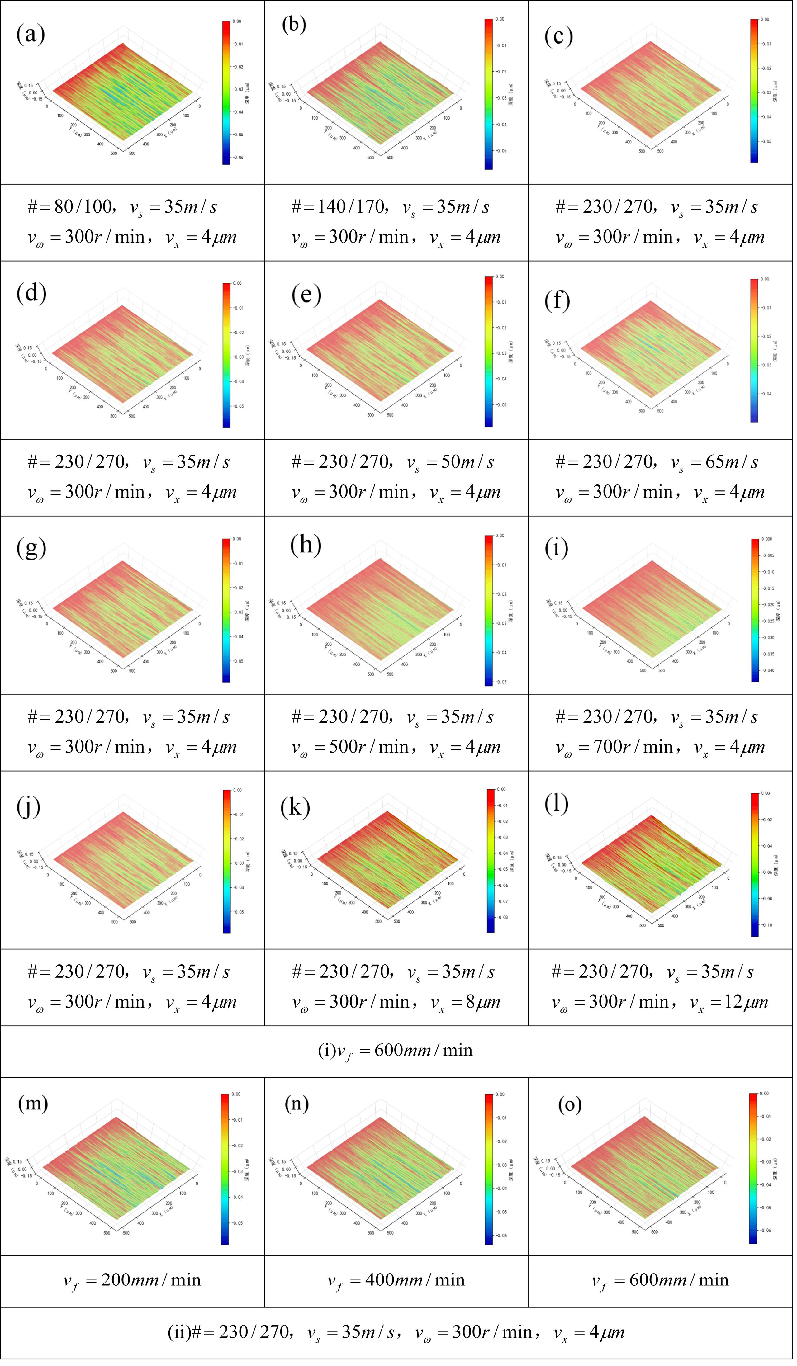
To visually observe the machining effect, three representative parameter combinations were selected from each group of experimental parameters, and the surface morphologies of the ground workpieces were extracted and analyzed. This further verifies the influence of different parameters on the surface microstructure.
The simulation results are shown in Fig. 4. It can be observed from Fig. (a), (b), and (c) that the 80/100 mesh diamond grinding wheel, due to its larger abrasive grain size and higher abrasive protrusion height, produces a deeper machining depth on the workpiece surface, resulting in more material removal. As the abrasive mesh size decreases, the single-pass material removal depth on the workpiece surface reduces. The use of a larger-grain-size grinding wheel can thus improve material removal efficiency. In Fig. (d), (e), and (f), where the grinding wheel linear speed is increased, the material removal depth on the workpiece surface gradually increased with increasing wheel speed. This indicates that a higher wheel speed leads to a greater number of abrasives participating in machining on the same surface area per unit time. In Fig. (g), (h), and (i), with the increase in workpiece rotational speed, the maximum material removal depth on the workpiece surface decreases. This suggests that a higher workpiece rotational speed results in a smaller cutting depth per abrasive during each rotation of the workpiece, reducing the number of abrasives acting on the same surface area per unit time. In Fig. (k), (l), and (m), where the grinding wheel feed rate is increased, it can be seen that the cutting depth per workpiece rotation increased with the feed rate, leading to significant changes in surface material removal. In Fig. (m), (n), and (o), as the grinding wheel oscillation speed increased, the material removal depth per abrasive slightly decreased, which is beneficial for improving surface quality.
Analysis of Grinding Wheel Machining Uniformity Sc
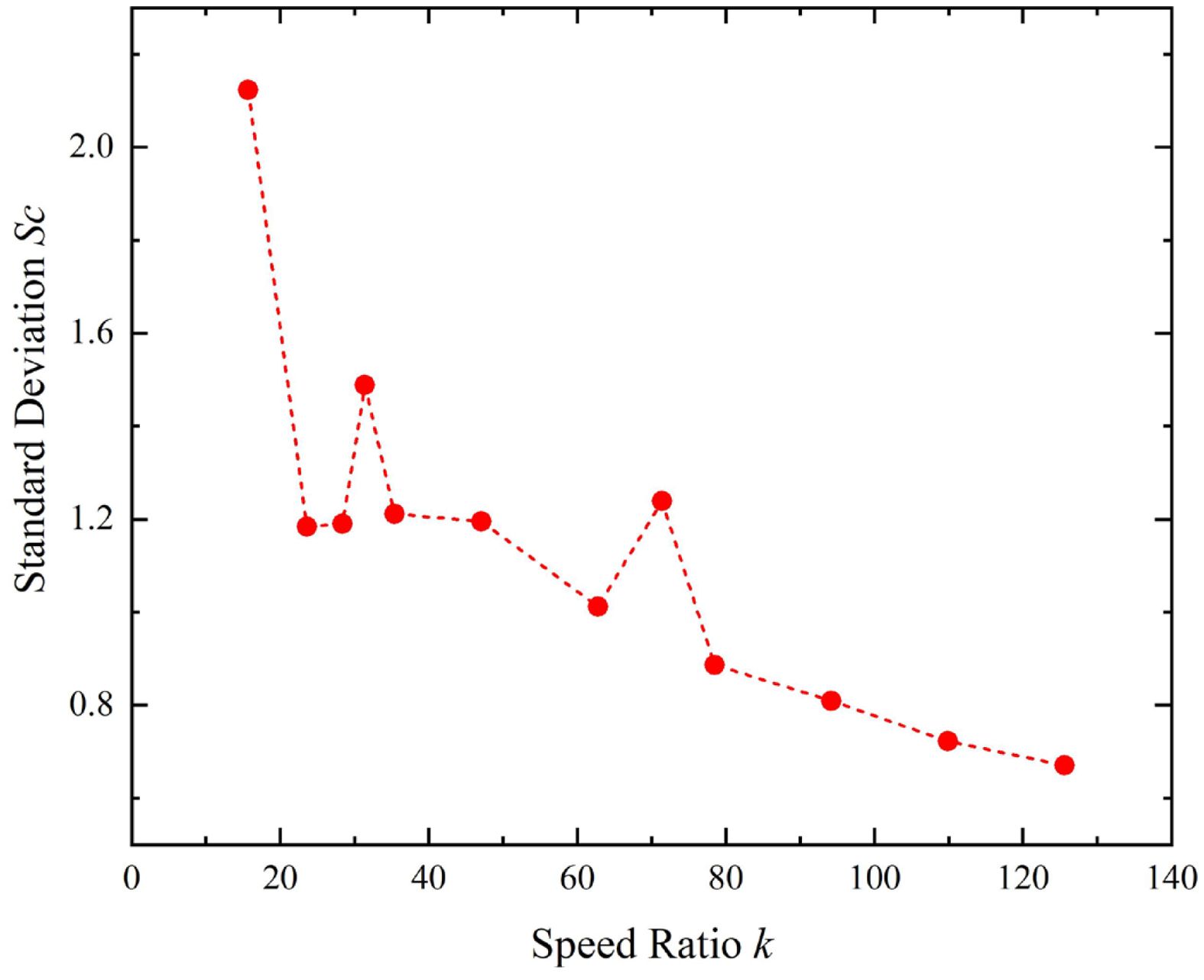
Since the machining trajectory is affected by the workpiece rotational speed and the grinding wheel oscillation speed, the ratio of these two (speeds) is thus taken as the independent variable for calculation.
The variation of standard deviation Sc with the speed ratio k is shown in the Fig. 5. As the speed ratio increases, Sc exhibits a downward trend, which indicates that the uniformity gradually improves with the increase of the speed ratio k. When k ∈ [80, 130], the downward trend of Sc slows down gradually, meaning that the impact of increasing k on the uniformity of the machining trajectory is weakening. However, excessively large k values may cause a certain parameter of the equipment to exceed the stable operation range of the system, leading to large vibrations and other adverse effects.
Analysis of motion simulation results for grinding wheel machining on workpiece surface
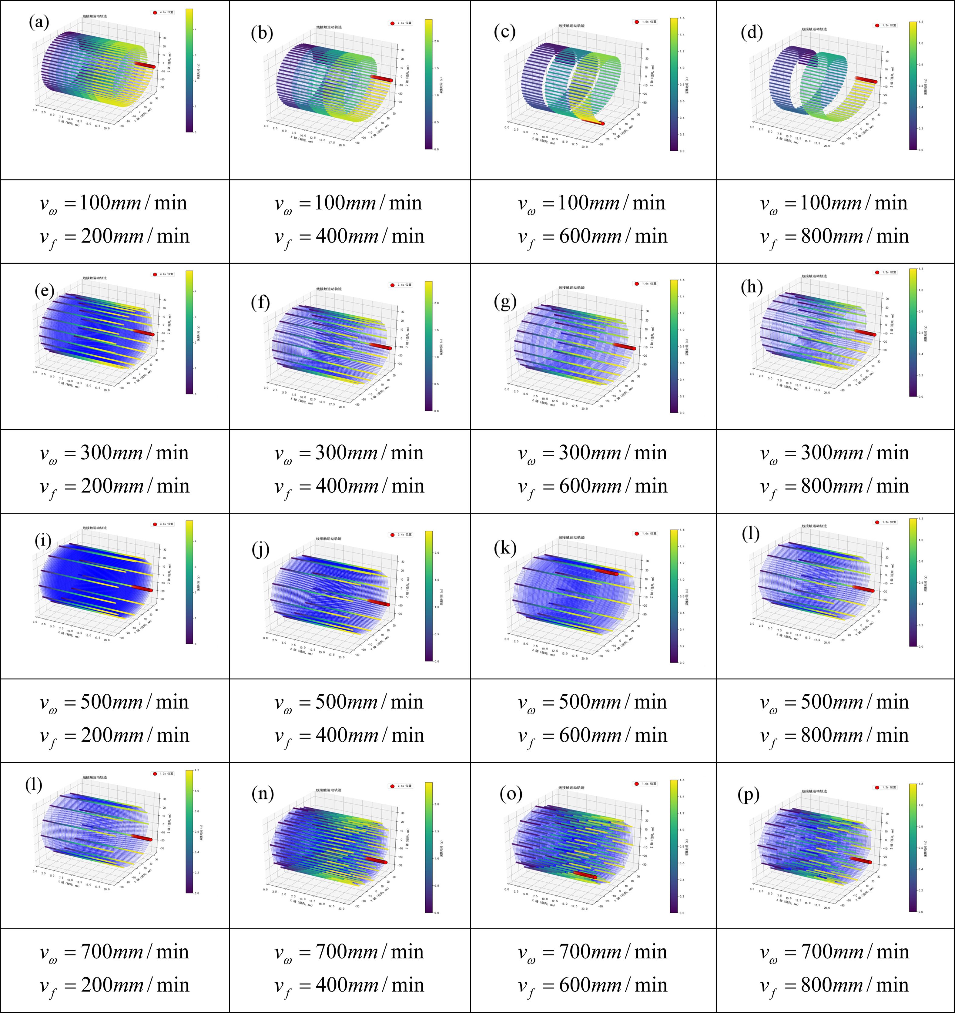
Kinematics simulation was performed on the machining contact points between the grinding wheel and the workpiece. With the grinding wheel width set to 5 mm, the contact zone was discretized into discrete points to observe their motion trajectories. Fig. 6 shows the trajectory simulation results. As indicated in Fig. (a), (b), (c), and (d), when the workpiece rotational speed is 100 r/min, incomplete coverage of the surface trajectory occurs as the grinding wheel oscillation speed increases from 200 mm/min to 800 mm/min. At this point, the speed ratio k gradually decreases. This implies that a low workpiece rotational speed cannot be paired with a high grinding wheel oscillation speed, which is detrimental to surface machining. In Fig. (e), (f), (g), and (h), with the workpiece rotational speed at 300 r/min, as the grinding wheel oscillation speed increases from 200 mm/min to 800 mm/min, At this point, the speed ratio k gradually decreases, the grinding wheel trajectory coverage is complete. However, the density of the trajectory decreases with the increase in the grinding wheel oscillation speed, suggesting that a lower oscillation speed can achieve a certain degree of spark-out effect. When the workpiece rotational speed reaches 500 r/min and 700 r/min, At this point, the speed ratio k increases. the density of the machining trajectory significantly increases. This indicates that selecting a high workpiece rotational speed is beneficial for improving surface quality. Additionally, according to Equation (19), increasing the grinding wheel oscillation speed can be regarded as reducing the single deep cutting depth of abrasive grains, which is conducive to enhancing the machined surface quality. Therefore, increasing the workpiece rotational speed while appropriately increasing the grinding wheel oscillation speed is conducive to improving the surface quality of machining. It can be seen that the trend of machining uniformity presented by the simulation results is consistent with the variation trend of standard deviation Sc with the speed ratio k.
|
Fig. 3 Schematic Diagram of the Grinding Process. |
|
Fig. 4 Surface morphology diagrams of single-pass machining simulation, where # is the abrasive grain size, vs is the grinding wheel linear speed, vw is the workpiece rotational speed, vx is the grinding wheel feed rate, and vf is the grinding wheel oscillation speed. |
|
Fig. 5 Schematic Diagram of Uniformity Variation with the K Value. |
|
Fig. 6 Simulation diagrams of contact trajectories between grinding wheel and workpiece. |
Experimental process
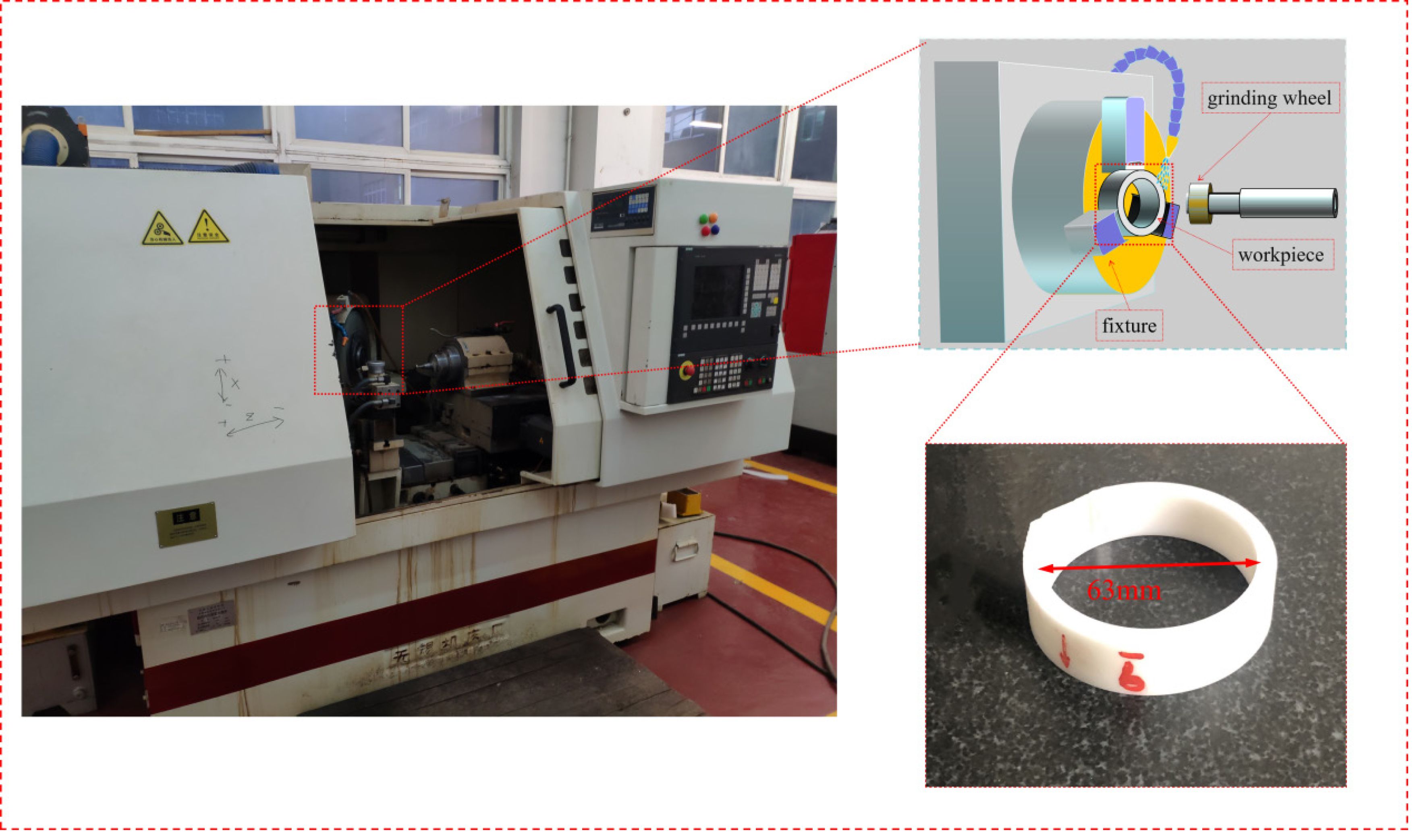
The experiments were conducted using an MK2710 internal and external cylindrical grinder manufactured by Wuxi Machine Tool Co., Ltd., with a maximum spindle speed of 36,000 r/min. Fig. 7 shows the machining schematic. A resin-bonded diamond grinding wheel with 100% concentration was selected, and the width of the grinding wheel was 5 mm.
Single-factor experiments and the response surface methodology were adopted in this experiment, and the experimental parameters were consistent with the simulation parameters. Based on the simulation results of the experimental trajectories, the oscillation speed of the grinding wheel was set to 500 mm/min. The machining was stopped when the total feed reached 50 μm. Before each machining operation, the grinding wheel was dressed using an alumina ceramic. All experiments were performed under cooling conditions with a 5% concentration water-based cutting fluid, at a flow rate of 100 L/min. After machining, the surface roughness of the machined surface was measured using a Taylor Hobson Surtronic roughness tester, and the surface morphology was observed using a Hitachi S4800 cold-field emission scanning electron microscope (SEM).
Results and discussion
Comparative analysis between simulation and experiment
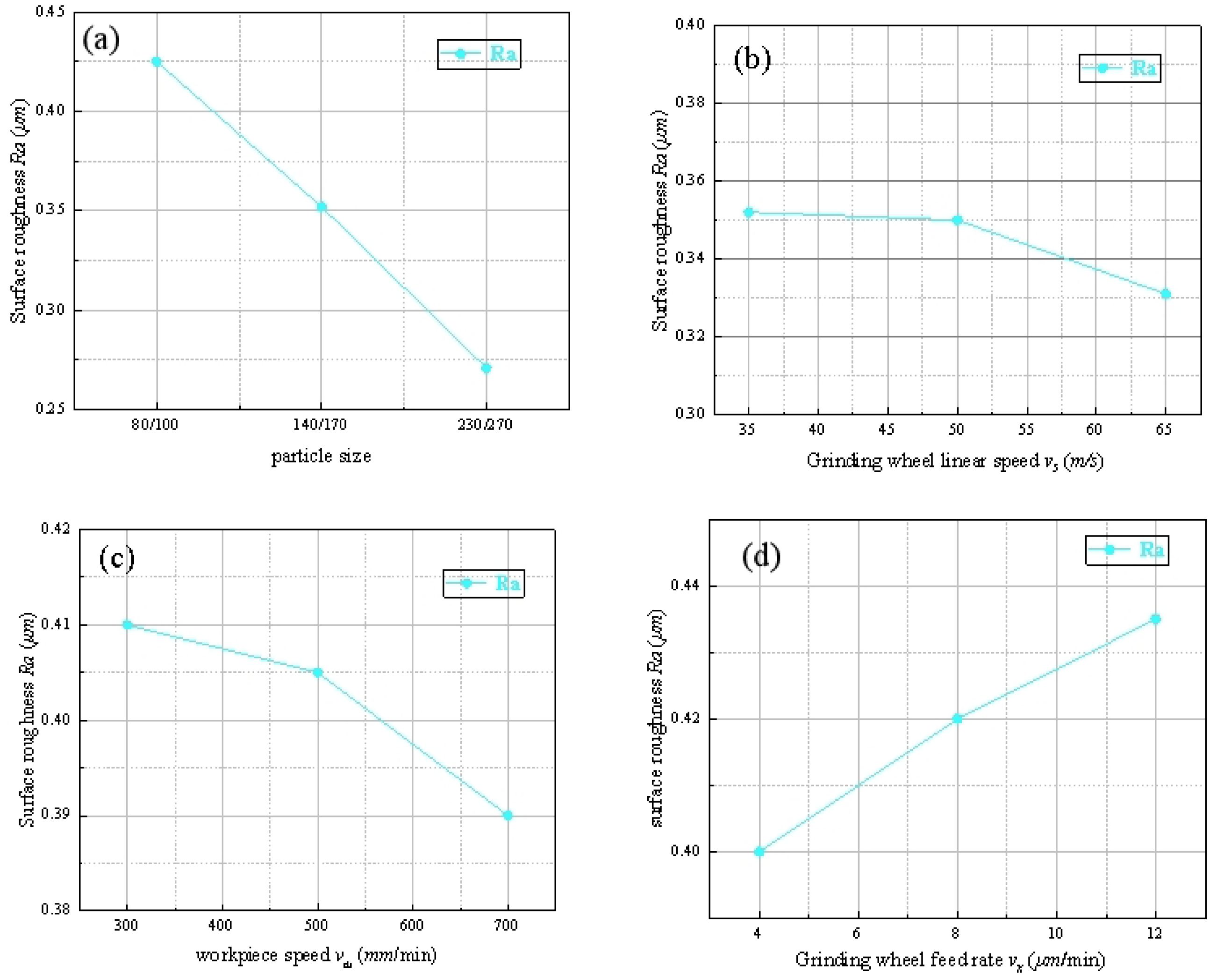
Each set of parameters was subjected to 8 simulations, and the roughness results of each simulation were recorded. The simulation results are presented in Fig. 8. Observing Fig (a), as the grinding wheel grit size decreases, the roughness gradually decreases. In Fig (b), as the grinding wheel linear speed increases, the overall change in roughness is slight, but the overall fitting trend shows a slight decrease. Similar discrepancies were also found in the studies of [11] and [12], which further supports this view. Fig. (c) indicates that increasing the workpiece rotational speed has a relatively significant effect on reducing the surface roughness; however, attention should also be paid to the reasonable configuration of the grinding wheel oscillation speed and the workpiece rotational speed mentioned in Section 3.2 to achieve better machining results. In Fig. (d), the grinding wheel feed rate has a relatively significant impact on the workpiece surface roughness.
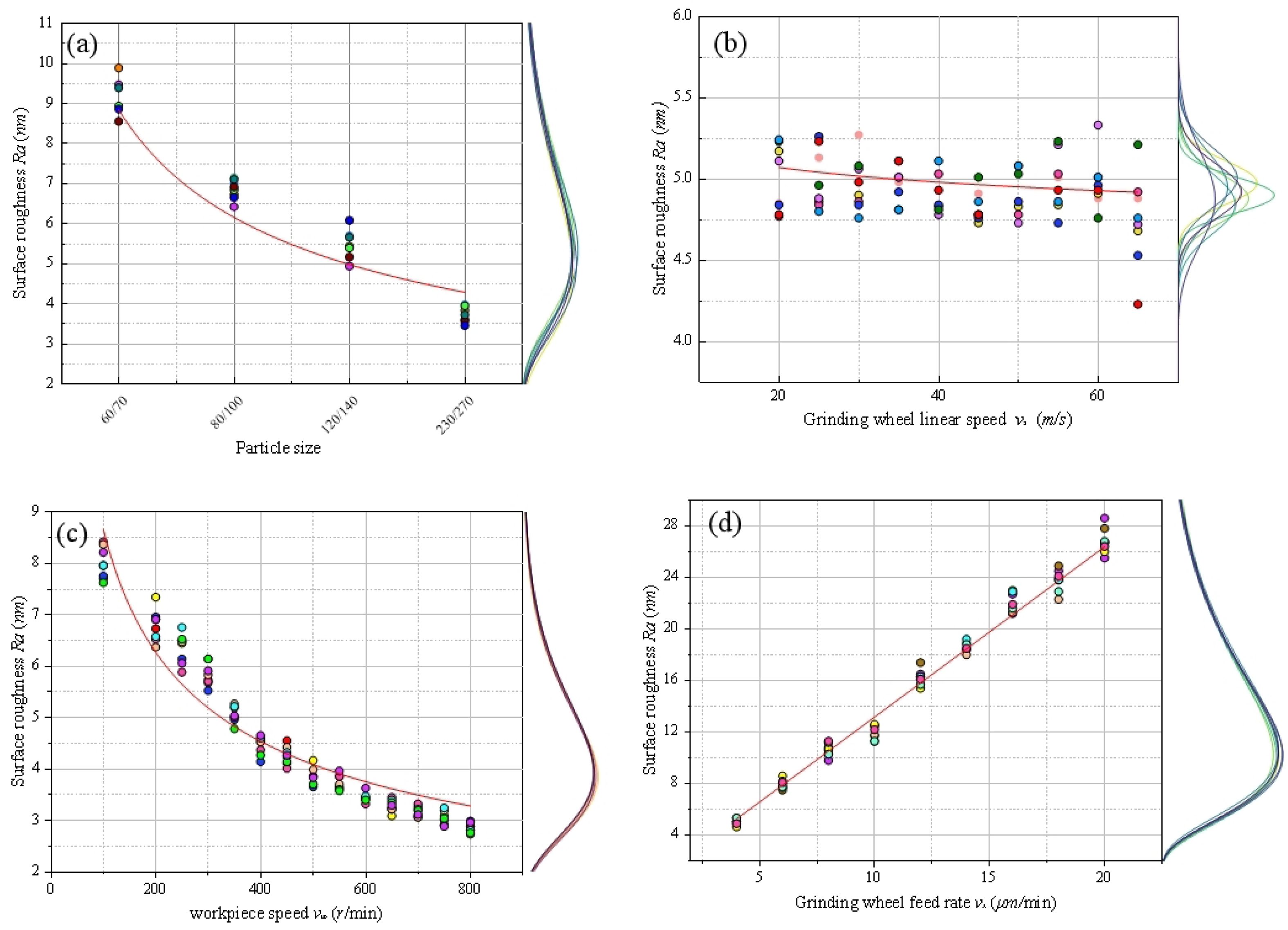
Three sets of parameters from the simulation parameters were selected for experiments, and the experimental results are shown in Fig. 9. Under the conditions of changing abrasive grain size, grinding wheel linear speed, workpiece rotational speed, and workpiece feed rate, the variation trend of roughness presented by the experimental results is basically consistent with that of the simulation results. However, the influence of the grinding wheel linear speed on roughness is not significant; therefore, the response surface methodology is adopted to conduct significance analysis of the experimental parameters.
Analysis of Results of Response Surface Methodology
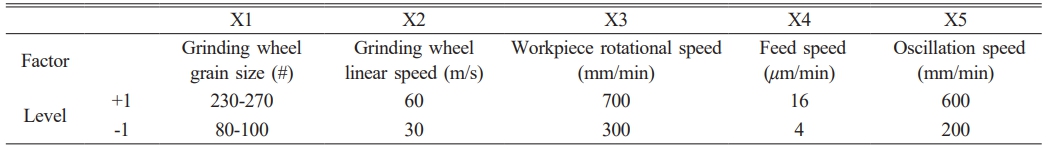
The factors and levels are coded. The factors are identified as five machining parameters, and two representative levels of them are selected, as shown in the Table 3:
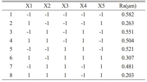
A 2⁵⁻² fractional factorial design is adopted, and the experimental scheme is generated via statistical software (Table 4). Each group of experiments is repeated three times, with the average value taken:
Calculate the total sum of squares:

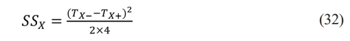
Calculate the sum of squares for each factor:
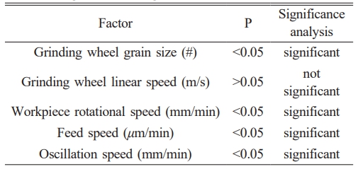
Using the P-value to judge the significance of the results, the results are shown in the Table 5:
Analysis using the response surface methodology shows that the influence of the grinding wheel linear speed is not significant. In Fig. 8(b) and 9(b), it can be seen that as the grinding wheel linear speed increases from 35 m/s to 65 m/s, the variation in roughness is very small. Combining the results of the response surface methodology with the experimental results, it can be concluded that the increase in grinding wheel linear speed is not the main factor affecting the machined surface roughness. Therefore, in actual machining, an appropriate grinding wheel linear speed can be selected as the machining parameter according to the equipment conditions.
Analysis of workpiece surface morphology
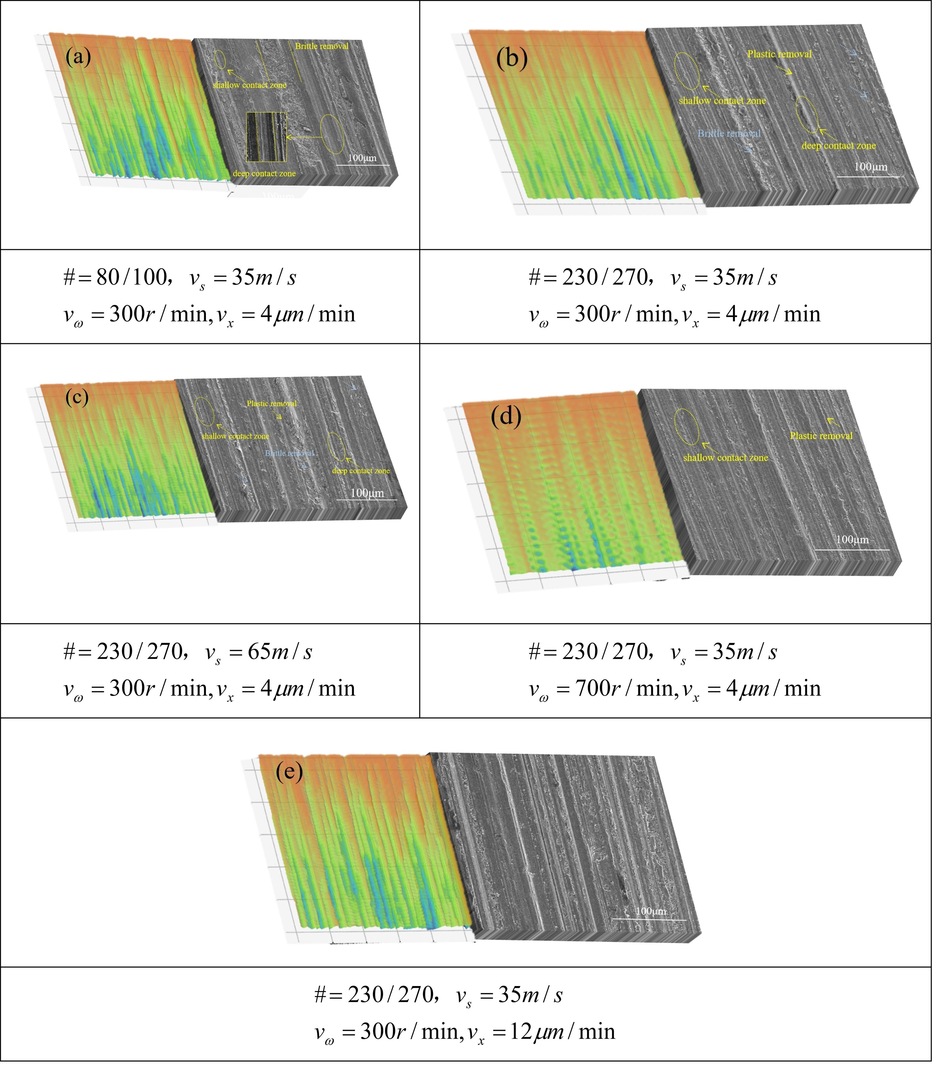
Five sets of experimental results were selected for observation using the SEM. Fig. 10 shows the material removal morphologies of the simulated surface and the experimental surface under the same parameters, where the simulated morphology is the surface morphology after a single machining pass, and the SEM morphology is the surface morphology after the completion of machining. All brittle materials exhibit damage evolution behaviors during material removal: crack-free plastic deformation, surface crack initiation, subsurface crack propagation to the surface, and brittle removal [28-30]. For inner circle machining, changing different machining will lead to changes in the number of abrasive grains involved in removal per unit area, as well as changes in the cutting length of the abrasive grains.
Observing the simulation results in Fig. 10(a), it can be seen that larger abrasive grains produce wider scratch widths than smaller ones, which also means that larger abrasive grains cause more surface brittle fractures. With the same abrasive grain size, increasing the grinding wheel rotational speed (Fig. 10(b) and Fig. 10(c)) leads to an increase in the number of abrasive grains acting on the same surface, resulting in the situation where the same position is cut by multiple abrasive grains. However, when increasing the workpiece rotational speed (Fig. 10(d)), this situation can be effectively improved: the cutting time of a single abrasive grain on the surface becomes longer, and more complete plastic removal traces appear on the surface.
Increasing the grinding wheel feed rate, which can be regarded as increasing the machining depth per revolution, leads to an increase in the cutting depth of the abrasive grains (Fig. 10(e)). This is manifested as more abrasive grains removing material in a state of deep contact, resulting in deeper grooves, and the surface quality also changes accordingly. The changes in surface material morphology under different parameters are consistent with the variation trends of surface roughness in Fig. 8 and Fig. 9.
|
Fig. 7 Schematic diagram of inner circle machining of zirconia sleeve. |
|
Fig. 8 Simulation trend diagram of Ra. |
|
Fig. 9 Trend diagram of experimental roughness. |
|
Fig. 10 Comparison of surface morphologies between single-pass machining simulation and SEM observation of workpiece surface. |
1. A simulation model for grinding zirconia sleeves with a narrow-grit-face-grinding-wheel was established. The surface quality of the inner circle grinding of the sleeve is mainly affected by the surface quality of a single grinding pass and the compactness of the grinding trajectory.
2. When machining the inner circle of workpieces with a narrow abrasive surface grinding wheel, the main influencing factors for the density of the machining trajectory are the grinding wheel oscillation speed and the workpiece rotational speed. Selecting an appropriate speed ratio k is conducive to improving the surface quality.
3. The final surface quality of the inner circle machining of the workpiece is related to the surface quality of single-circle machining. While pursuing machining efficiency, the final surface quality can be improved by adjusting machining parameters to modify the machining depth per circle. For example, with a grinding wheel linear speed of 35 m/s and a grinding wheel feed rate of 12 μm/min, increasing the workpiece rotational speed can reduce the machining depth per circle and optimize the surface quality.
4. During the inner circle machining process, the process parameters can be optimized according to the method proposed in this paper to improve the applicability of ordinary grinding wheels, reduce the customized production of grinding wheels required for sleeves of different sizes, and save machining costs.
This research was supported by the Gansu Provincial Natural Science Foundation [grant number 23JRRE0736]; and the Science and Technology Plan of Qinzhou District, Tianshui City [grant number 2025-SHFZG-4765].
- 1. J. H. Biswas, Jagadish, and A. Ray, Int. J. Mach. Mach. Mater. 21[2] (2019) 115-137.
-

- 2. S. Qu, Y. Gong, Y. Yang, M. Cai, and Y. Sun, Ceram. Int. 44[12] (2018) 14742-14753 .
-
- 3. S. Agarwal, Ceram. Int. 42[5] (2016) 6244-6262.
-
- 4. W. Liu, Z. Deng, Y. Shang, and L. Wan, Ceram. Int. 43[1] (2017) 1571-1577.
-
- 5. S. Dzebo, J.B. Morehouse, and S.N. Melkote1, Mach. Sci. Technol. 16[3] (2012) 355-379.
-
- 6. C. Wei, S. Li, Y. Wang, K. Wang, J. Zhao, and S. Liu, J. Ceram. Process. Res. 26[5] (2025) 754-766.
-
- 7. J. Sun, J. Huang, Z. Tian, Z. Xia, L.Wang, and Y. Zhang, J. Ceram. Process. Res. 25[6] (2024) 975-984.
-
- 8. A. Choudhary and S. Paul, Ceram. Int. 47[21] (2021) 30546-30562.
-
- 9. H. Yang, H. Zheng, and T. Zhang, Tribol. Int. 199[35] (2024) 109935.
-
- 10. J. Guo, P. Long, and Y. Zhao, Micromachines-basel 15[5] (2024) 614.
-
- 11. H. Yan, Y. Wu, and H. Wang, IOP Conf. Ser.: Mater. Sci. Eng. 399 (2018) 1-15.
-
- 12. S. Li, C. Wei, and X. Li, Mater. Res. Express 10[2] (2023) 1-16.
-
- 13. X. Zhou and F. Xi, Int. J. Mach. Tool. Manuf. 42[8] (2002) 969-977.
-
- 14. C. Li, X. Li, Y. Wu, F. Zhang, and H. Huang, Int. J. Mach. Tool. Manuf. 143[5] (2019) 23-37.
-
- 15. Z. Ge, S. Li, Y. Wu, Y. Sha, J. Sun, and J. Tian, J. Ceram. Process. Res. 23[5] (2022) 685-693.
-
- 16. H. Pelletier, C. Gauthier, and R. Schirrer, Mater. Lett. 63[20] (2009) 1671-1673.
-
- 17. C. Gauthier, S. Lafaye, and R. Schirrer, Tribol. Int. 34[7] (2001) 469-479.
-
- 18. C. Li, K. Wang, Y. Piao, H. Cui, O. Zakharov, Z. Duan, F. Zhang, Y. Yan, and Y. Geng, Int. J. Mach. Tool. Manuf. 201 (2024) 104-197.
-
- 19. J. Yang, J. Zhang, Y. Zhou, Q. Deng, H Chen, C. Chen, T.H. Beri, and B. Lyu, Int. J. Adv. Manuf. Tech. 131[5-6] (2024) 1845-1858.
-
- 20. S. Agarwala and P.V. Raob, Int. J. Mach. Tool Manuf. 50[12] (2010) 1065-1076.
- 21. Q. Gu, Z. Deng, L. Lv, T. Liu, H. Teng, D. Wang, and J. Yuan, Int. J. Adv. Manuf. Tech. 113[11-12] (2021) 821-836.
-
- 22. D. Axinte, P. Butler-Smith, C. Akgun, and K. Kolluru, Int. J. Mach. Tool. Manuf. 74 (2013) 12-18.
-
- 23. S. Chakrabarti and S. Paul, Int. J. Adv. Manuf. Tech. 39[2] (2008) 29-38.
-
- 24. T. Jin, D.J. Stephenson, G.Z. Xie, and X.M. Sheng, CIRP. Ann 60[1] (2011) 343-346.
-
- 25. S. Mihić, R. Dražumerič, and F. Pušavec, P.I. Mech. End. B-J. End. 11 (2016) 1-9.
-
- 26. Z. Feng, H. Yi, A. Shu, and L. Tang, Int. J. Adv. Manuf. Tech. 130 (2024) 475-490.
-
- 27. T.G. Bifano, T. Dow, and R.O. Scattergood, J. Eng. Ind. 113[2] (1991) 184-189.
-
- 28. H. Huang, X. Li, D. Mu, and B. R, Int. J. Mach. Tool. Manuf. 161 (2021) 1-15.
-
- 29. P. Dhaladhuli, R. Amirtham, and J.N. Reddy, Mech. Adv. Mater. Struct. 22[29] (2022) 3187-3208.
-
- 30. C. Li, F. Zhang, B. Meng, X. Rao, and Y. Zhou, Mater. Design 125 (2017) 180-188.
-
 This Article
-
2026; 27(1): 24-36
Published on Feb 28, 2026
- 10.36410/jcpr.2026.27.1.24
- Received on Aug 1, 2025
- Revised on Nov 6, 2025
- Accepted on Nov 14, 2025
Services
- Abstract
introduction
modeling of zirconia internal cylindrical machining
simulation results and analysis
zirconia sleeve inner circle grinding test
conclusions
- Acknowledgements
- References
- Full Text PDF
Shared
Correspondence to
- Yong Sha, Hao Zhang
-
aSchool of Mechanical Engineering, Gansu Vocational University of Industry Technology, Tianshui 741000, China
bGansu Provincial 3D Printing Industry Technology Center, Tianshui 741000, China
Tel : 0938-8369207 Fax: 833-401-2695 - E-mail: 3ddyzx@gsjdxy.edu.cn
Clean-Energy Research Institute(CRI), Hanyang University, 222, Wangsimni-ro, Seongdong-gu, Seoul, 04763, Korea
E-mail: jcpr@hanyang.ac.kr