


- Rare earth substituted M-type lead hexaferrite: synthesis, electrical and magnetic properties
Burcu Ertuğa,*
aBilgi University, Faculty of Engineering and Natural Sciences, 34060 Istanbul, Turkey
This article is an open access article distributed under the terms of the Creative Commons Attribution Non-Commercial License (http://creativecommons.org/licenses/by-nc/4.0) which permits unrestricted non-commercial use, distribution, and reproduction in any medium, provided the original work is properly cited.
In this article, the synthesis and the electrical and magnetic characterization of the M-type lead hexaferrite were presented. Rare-earth substituted lead hexaferrite was synthesized by the traditional ceramic process. The final product was obtained by sintering the lead hexaferrite compact at 950ºC for 2 h. According to the XRD analysis, secondary phases did not appear in the patterns. The electrical polarization curve of the sample did not confirm the ferroelectric response. The dielectric constant vs. frequency indicated a reduction trend. As observed from the polarization curve, the polarization value changed between 0.8 and -0.8 µC/cm2 under the voltage of 5.76 kV. The high symmetry of the crystal in this sample is proposed to be the origin of the absence of ferroelectric response. Vibrating sample magnetometer (VSM) measurements confirmed the ferrimagnetic behaviour for both RT and low temperature. The saturation magnetizations (Ms) were found to be 7.54-8.08 emu/g in the temperature range of 7-22 K and the highest coercivity value was found to be 1.2 kOe and this result depicts the magnetically soft nature and multi-domain structure. The results showed that the obtained lead hexaferrite sample has acceptable magnetic properties.
Keywords: Hexaferrite, Polarization, Dielectric, Saturation magnetization, Permanent magnet.
Ferrite materials cover three groups of magnetic materials, namely: ferrite spinels, ferrite garnets and hexagonal ferrites. The last group which are polycrystalline hexagonal ferrites exhibit very high uniaxial magnetic anisotropy. That is why they have become ideal permanent magnets. M-type hexaferrites having the general formula of MFe12O19 (where M is Ba, Sr or Pb) can be used in many applications such as the permanent magnets, high density magneto-optics, magnetic recording media and so on. The requirements for these applications are high saturation magnetization and coercivity, large magneto-crystalline anisotropy, together with excellent chemical stability [1-7].Furthermore, for specific applications they are able to compete with the metal-based permanent magnets [8]. Among the M-type hexaferrites, the Ba-hexaferrite was the first one of which characterization was made. Because their coercivity is tunable, their saturation magnetization, their permittivity and their permeability are high, they are chemically stable, these materials have become one of the popular research field. Among their uses, there are biological applications, the automotive industry and telecommunications sector [9]. Apart from the permanent magnets described above, these uses might contain catalysis, humidity sensors, MRI, data storage devices, satellite communication and so on [10]. In order to tailor the magnetic properties of the common hexaferrites, the replacement of Ba2+ or Sr2+ cations and also, of Fe3+ cation is carried out [9]. Since their discovery in 1950, some specific electrical and magnetic behaviours of the hexaferrites have drawn interest to these materials due to the functionality of especially Sr and Ba hexaferrites. These magnetic behaviours are related to the particle size, the particle shape and the synthesis methods [11]. Similar to the structures of other hexaferrites, the magnetoplumbite lead hexaferrite can be considered as a combined structure of the spinel and hexagonal blocks. In this structure, the lead cations and oxygen anions build up a dense packing along the c axis in the sequence of ten layers of ABABACBCBC where Pb2+ cations are found in the third and eighth layers [12].
In the dielectric materials, there are tightly bound electrons to the nucleus, which are not mobile. However, under the electric field, a slight displacement of the cloud of electrons is observed from the positive nucleus, which results in the electronic polarization. Polar molecules show orientational polarization. In these molecules, the electrons are not shared symmetrically. Thus, there is a separation between the net positive and negative charges. Under the electric field, a torque is exerted on the molecules and this torque has a tendency to align them with the field. The ionic polarizability emerges when the ions of molecules are slightly displaced [13-16]. Dielectric materials can be defined as the insulator materials which do not exhibit electrical conductivity. Between the valence and conduction bands of these materials, there is a large energy gap. Despite the fact that conductivity of the electric current is not observed, under the applied electric field a polarization takes place in these materials. An electric dipole is built up in these materials through the shift of charge balance under applied electrical field. The electrical insulators or capacitors are the examples of the applications of dielectric materials. The ability to store charge with respect to vacuum is said to be dielectric permittivity and it is commonly referred as dielectric constant. Under applied electric field, E (V/m) the polarization, P (C/m2) can be induced in the insulators (dielectric materials) [17-21]. When the frequency rises, the net polarization in the material decreases since each of the polarization mechanisms ceases to make a contribution causing the dielectric constant drop. At the higher frequencies, approximately above 1015 Hz, there is not any polarization mechanism which can rapidly switch to be able to remain in step with the applied electrical field. Thus, the polarization ability of the material is lost leading to the drop of the dielectric constant to one (the value of the vacuum) [22-25]. As a result of the experimental measurements, it is possible to obtain various types of polarization versus electrical field (P-E) loops. Apart from the typical ferroelectric hysteresis curves. elliptical P-E curves might also be observed. It might be difficult to estimate if the study material exhibits ferroelectricity or not. In some cases, it is possible to misinterpret a non-intrinsic type of polarization under applied electrical field as an evidence for the presence of ferroelectric behaviour [26-29, 12].
Several investigators studied the partial substitution of rare earth elements for the cations of Sr [30] or Ba [31] in order to improve the magnetic properties of the hexaferrites. Several researches studied Pr substitution on the magnetic and electrical properties of Sr-hexaferrite [32], the effect of La-Pr-Co co- substitution on the mag prop CaSr-hexaferrite [33], the effects of Pr-Co content on the magnetic properties of Sr-hexaferrite [34], the influence of La-Mn substitution on the magnetic properties of Sr-hexaferrite [35]. Some other researchers conducted magnetic studies on the Cr substituted CaSrLa-hexaferrite magnets [36], electrical and magnetic characterization of rare earth substituted Sr-hexaferrite [37] and the magnetic studies of Bi and La substituted Sr-Ba hexaferrite powders [38].
The substitution of La for Sr increased both the saturation magnetization and coercivity. However, substituting Pr in the Sr site by increased the coercivity. Also, while substituting various rare earth elements for Sr, the coercivity increased whereas the saturation magnetization dropped [39]. It is possible to improve the magnetic properties of the lead hexaferrite through partially substituting the non-magnetic cations such as La3+, Ho3+, Al3+, Bi3+ in the sites of Pb2+ or Fe3+ [40].
The formation of Ba or Sr-hexaferrites takes place above 1250 °C and the formation of La-hexaferrite occurs at 1360 °C. On the other hand, in the lead hexaferrite the formation of the magnetic phase takes place at a low temperature. That is why there is a specific research interest on the PbFe12O19 material [27]. With respect to Ba and Sr hexaferrites, PbFe12O19 ferrimagnets have been less examined owing to the environmental concerns. These environmental effects are related to the chemical stability of lead hexaferrite such as the decomposition to PbO that takes place at 950 °C. Another drawback is the relatively lower saturation magnetization and the anisotropy field of Pb hexaferrite in comparison to other M-type ferrite compounds. The modification of the magnetic properties is maintained by the substitution of the metal-cations. The long-range interaction within the material is changed because of the cation substitution, which in turn results in the modification of magnetic properties [41]. Mahdiani and co-workers (2017) reported the magnetic properties of PbFe12O19 nanostructures which were produced by the sol-gel auto-combustion method at 900 °C for two hours. They produced a nanostructure that exhibited a high coercivity value of approximately 5.1 kOe [42]. In a very recent study, Pb1-xCrxFe12O19 with a grain size of 53-63 nm. was prepared. Cr3+ substitution initially increased the saturation magnetization reaching a maximum value of 64 emu/g for 30% Cr3+ and with further increase, the Ms value dropped. Also, for this composition, a minimum coercivity value of 6.54 kOe was obtained [43]. Ansari and co-workers (2014), prepared the nanoplates and nanoparticles based on the PbFe12O19 by the sol-gel auto-combustion method, the obtained products exhibited high coercivities of 5.6 kOe [44]. In a study of Tan and Wang (2011), PbFe12O19 powders were synthesized using the sol-gel method to produce a hexagonal structure. Following the sintering at 1000 °C for one hour, a strong ferromagnetism was observed at room temperature for the obtained PbFe12O19 ceramics [2].
In the current paper, the electrical polarization and the magnetic behaviour of the lead hexaferrite prepared through the traditional ceramic method were investigated. Our objective is to examine the effect of the rare earth elements (La, Y) on the electrical and the magnetic response.
Synthesis of Lead Hexaferrite
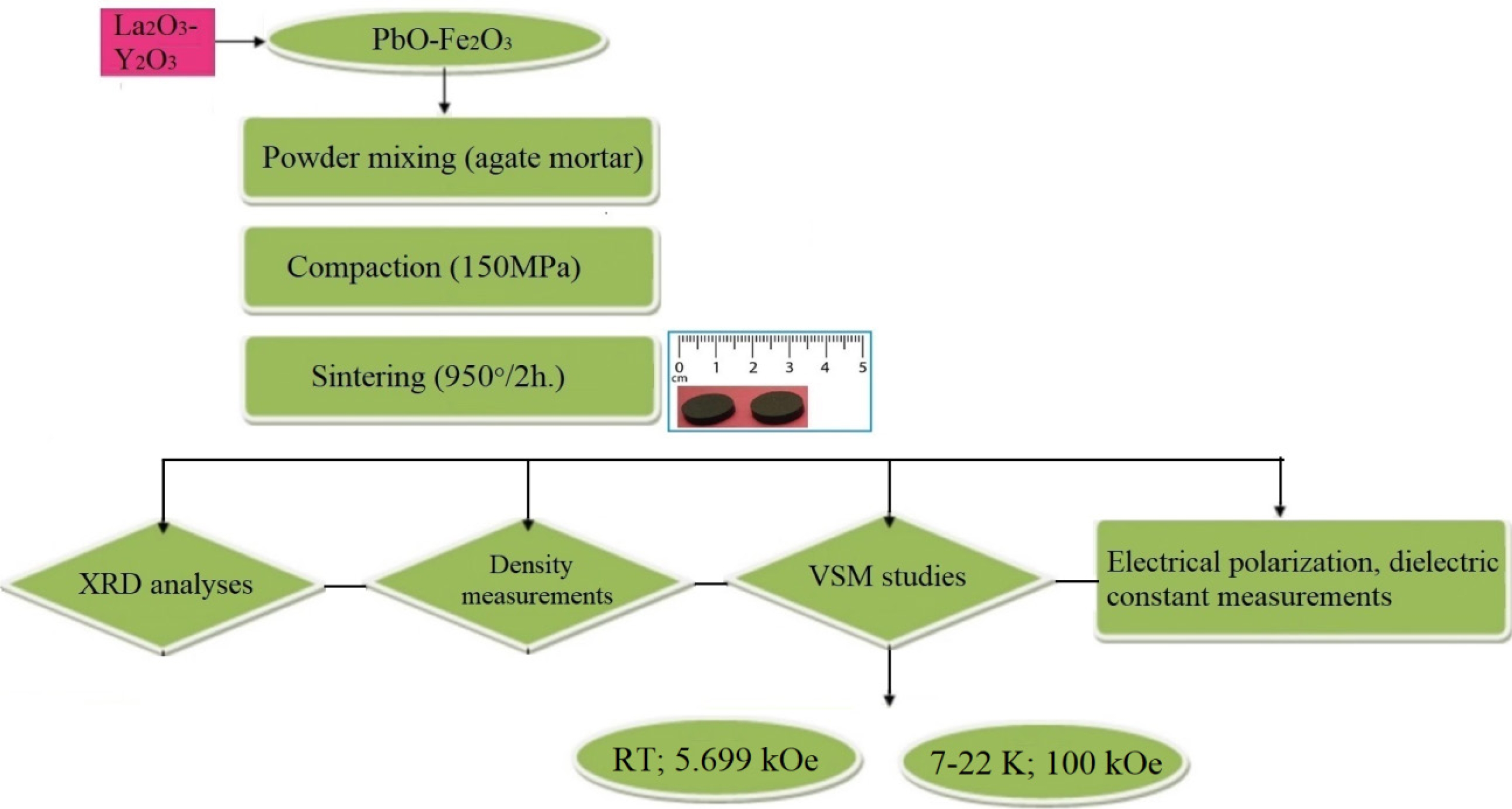
M-type lead hexaferrites with the compositions of PbRExFe12-xO19 (x = 0.2) were produced by the solid-state reaction. 3 g of the precursor powders were weighted and PbCO3 was used as the source of Pb and Fe2O3 as the source of Fe. The mass of the precursor powders; 98% hematite (Fe2O3) (ZAG Kimya), 99% PbCO3 (Refsan), 99.5% La2O3 (Merck) and 99% Y2O3 (Merck) were taken based on the chemical formula. The preparation of the Pb-hexaferrite samples covered three steps: the mixing of the starting powders, compaction and the sintering of the powders. The process diagram showing a summary of the experimental work is shown in Fig. 1. The precursors used in this study were hematite, Fe2O3 and PbO. Appropriate amounts of the Fe2O3, PbCO3 and other powders of La2O3 and Y2O3 were were subjected to milling in the agate mortar for a sufficient duration. The powder mixture had a Pb/Fe ratio of 1:12. The stearic acid was used to enhance the effectiveness of the milling. Following the mixing, the powder mixture was pressed into a compact sample using a hyraulic press (Sahinler) with stainless steel die under a pressure of 150 MPa for 60 seconds. The samples were 10 mm. in diameter and 3 mm. in thickness. Afterwards, the samples were sintered under the atmospheric condition using (Nabertherm) at 950 °C for 2 h. at the heating rate of 5 ºC/min. in order to synthesize the compound of PbFe12O19.
Characterization Studies
X-ray Analysis of Lead Hexaferrite
The density of the sintered sample was calculated by using the measured diameter and the thickness and precisely taking the mass of the sample. The average density was presented as the mean value of the two densities obtained from different pellets.
The identification of the present crystalline phases was done through X-ray diffraction (XRD) measurements with the help of a X-ray diffractometer (Rigaku DMax2200). The XRD pattern collection was made in the Bragg angle range of 20-60 º. The XRD data was collected at room temperature using Cu Kα radiation (λ= 1.5406A°) in the 2Θ range of 30-40 ° at the slow scan speed and then the crystalline phases present in the sample were identified. The crystallite size was calculated by the Debye-Scherrer equation (1) :
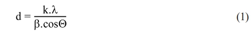
d shows the crystallite size; k value refers to Scherrer constant; λ indicates wavelength of X-rays and the β value stands for Full Width At Half Maximum (FWHM). The reader can refer to the study to obtain the details of the calculation[43]. The lattice parameters a and c were calculated by Equation (2):
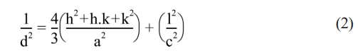
In Equation (2), d refers to interplanar spacing; hkl refers to Miller indices and a and c are the lattice parameters. The cell volume, Vcell was calculated by Equation (3):

Electrical Characterizations
The electrical characterizations of the study were carried out in two steps. The electrical polarization measurements and the dielectric measurements. The electrical polarization measurements were performed by Keysight E4980AL LCR meter under the applied voltages of various values. Polarization (μC/cm2) curves as a function of the electric field (kV/cm) were plotted. Secondly, the dielectric constant of the lead hexaferrite sample was measured as a function of frequeny in the range of 0.1-100 kHz.
Magnetic Characterization of Lead Hexaferrite
The study of the magnetization parameters was conducted with the help of Dexing Magnet VSM 550 vibrating sample magnetometer (VSM) and the magnetization loops were obtained at room temperature from the sample having crystalline grains of random orientation under applied magnetic field of 5.699 Oe. In addition, the magnetic parameters of the samples were measured in the range of 7-22 K under an applied magnetic field of ± 100 kOe.
|
Fig. 1 Process diagram of the experimental work. |
The average density of the lead hexaferrite sample having 0.2% of La and Y was calculated to be 3.65 g/cm3 (porosity of 8.75%) by the dimensions and the mass of the sample whereas the estimated X-ray density was calculated to be 2.70 g cm3. Similarly, in a previous study, the effect of copper-substitution in the lead hexaferrites prepared by co-precipitation method was examined [45]. According to the study of Parmar and co-workers (2020), the density of the un-substituted lead hexaferrite was 3.98 g/cm3 [45].
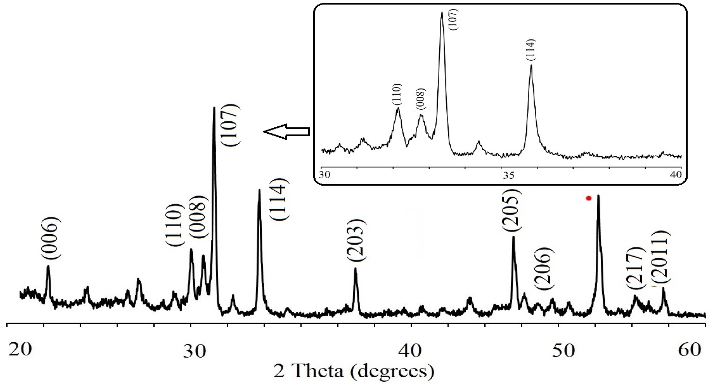
XRD diagram of the PbLa0.1Y0.1Fe11.8O19 recorded at room temperature were presented in Fig. 2. The sample demonstrated a single hexaferrite phase structure of PbFe12O19, consistent with the standard pattern that belongs to P63/mmc group with JCPDS file no (43-0002). This indicated that PbCO3 and Fe2O3 precursors were converted fully into the hexagonal phase of PbFe12O19 and La3+-Y3+ ions were successfully replaced the Fe3+ cations in the hexaferrite lattice after sintering at 950 °C. The principle reflections had the d-spacings (dhkl) corresponding to the peaks of (107) and (114). These Miller indices were used to estimate the values of the lattice constants and the lattice parameters of a and c were calculated as 5.59A and 26.96A°, respectively and based on the parameters; c/a ratio was estimated to be 4.82 and unit cell volume Vcell was calculated as 729.56 A°3. It was obvious that there was a change in the values of the structural parameters. This result might be due to the fact that the average ionic radii of 0.9 Å for Y3+ and 1.061 Å for La3+ are larger to that of Fe3+ (0.63 Å) [46]. The improvement in the unit cell volume by the increase of the ionic radii is because of the cationic filling on the site of the magnetic cation [47].
Average crystallite size, DXRD was calculated to be 70.83 nm. by the Scherrer method where k constant is 0.89 for the hexagonal crystal systems as shown in Table 1. For the electrical characterization studies, initially the occurrence of ferroelectric behaviour in the substituted lead hexaferrite was discussed.
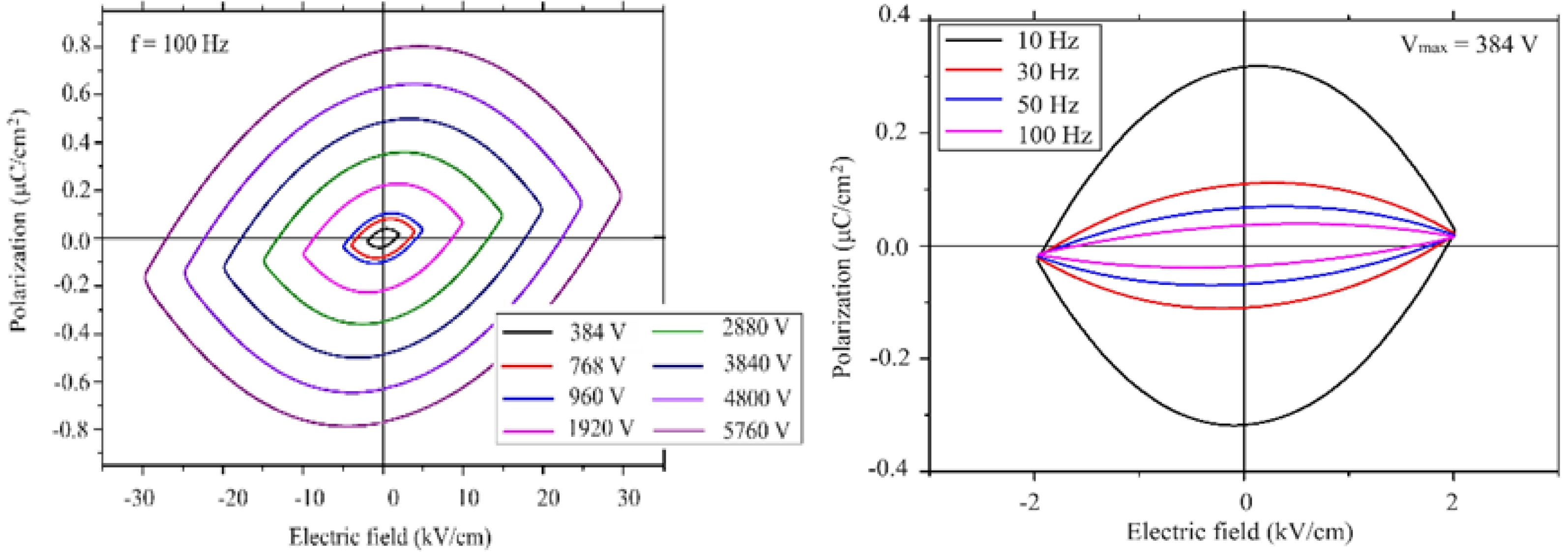
In order to find out whether the sample had ferroelectric property, the pellet sample was characterized using the electrical polarization curve at various frequencies and under different applied voltages. The polarization data was collected at room temperature. As an example, a polarization curve of elliptical shape might be mistaken for a ferroelectric response. The leakage current in the studied material might result in an observed elliptical shape in the polarization curve [48]. The space group of our sample is P63/mmc, which is not a polar space group. Because of the high symmetry of the crystal in this sample, it seems unlikely to observe a ferroelectric behaviour. However, since our sample is a magnetoelectric material (coupling between polarization and magnetization) [49]. The electrical polarization might be induced by the magnetic field.
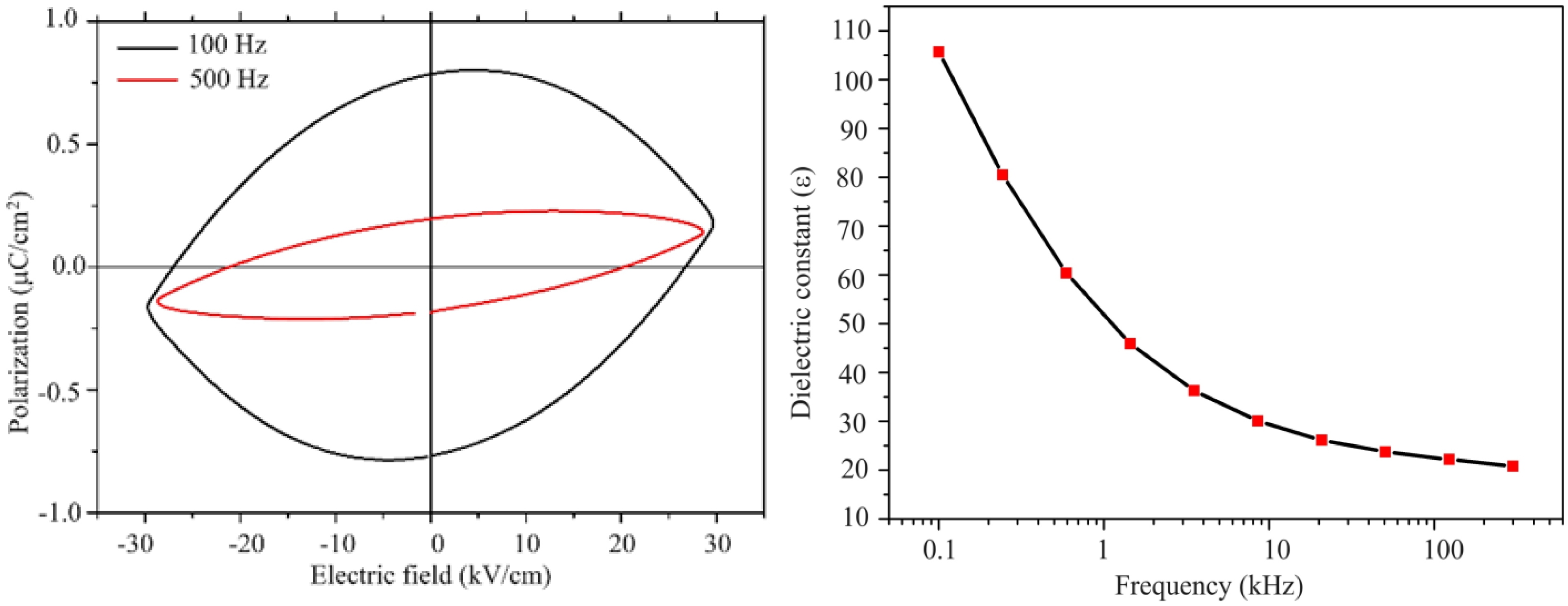
The measured polarization behaviour of the sample was similar to that of linear resistor in a previous study [50], which implies that this material exhibited a poor insulation behaviour. Since the high frequencies might restrict the contribution of the dipoles by the space charges, the measurements were carried out at 100 Hz under the maximum voltage and still under the maximum voltage at 500 Hz. Large reduction of the polarization was observed as a a function of frequency. This was related to the conductivity of the sample, which resulted in the space charges. As the voltage increased, the polarization linearly increased. A non-linear increase would indicate the domain motion, which is related to ferroelectric behaviour. A symmetric curve is observed for the linear resistor with respect to the horizontal and vertical axis [50]. This was the case observed for our sample. There was not any evidence of ferroelectric response in the lead hexaferrite sample as can be seen from Fig. 3, 4. At room temperature the dielectric measurements of PbLaxYxFe12-2xO19 (x = 0.2) was carried out as a function of frequency. The dielectric constant shows the capacity of a material to store electrical energy under applied electrical field [18]. Fig. 4 displays the dielectric constant (ε) for the sample of La-Y substituted lead hexaferrite from the frequency value of 0.1 kHz to the exceeding value of 100 kHz. According to the electrical polarization curve, the symmetrical values of the sample at 5.76 kV were determined to be 0.8 and -0.8 µC/cm2, which was 1.5 times higher than the reported value of 0.6 µC/cm2 from Al-substituted Ba-hexaferrite, measured under an electrical field of 110 kV/m at RT [51].According to the result of an earlier study, pure Ba- and Sr-hexaferrites produced by a modified ceramic method exhibited a ferroelectric property. The spontaneous polarization was detected upon application of an electrical field value of 100-300 kV/m [51].Also, a spontaneous polarization was determined in the Ba-hexaferrite at RT, which revealed a ferroelectric hysteresis behaviour. The ferroelectric polarization in the Ba-hexaferrite is suggested to be originated from the existence of FeO6 octahedron in the perovskite-like hexagonal structure and also, from the Fe3+ shifting from the center of this octahedron [52]. Similar studies were conducted for Sc substituted Ba-hexaferrite [53]and for the single crystal of Sc substituted Sr- and Ba- hexaferrite[51].In addition, the electrical polarization measurements at different frequencies demonstrated that the reduction of polarization occurred with increasing frequency.
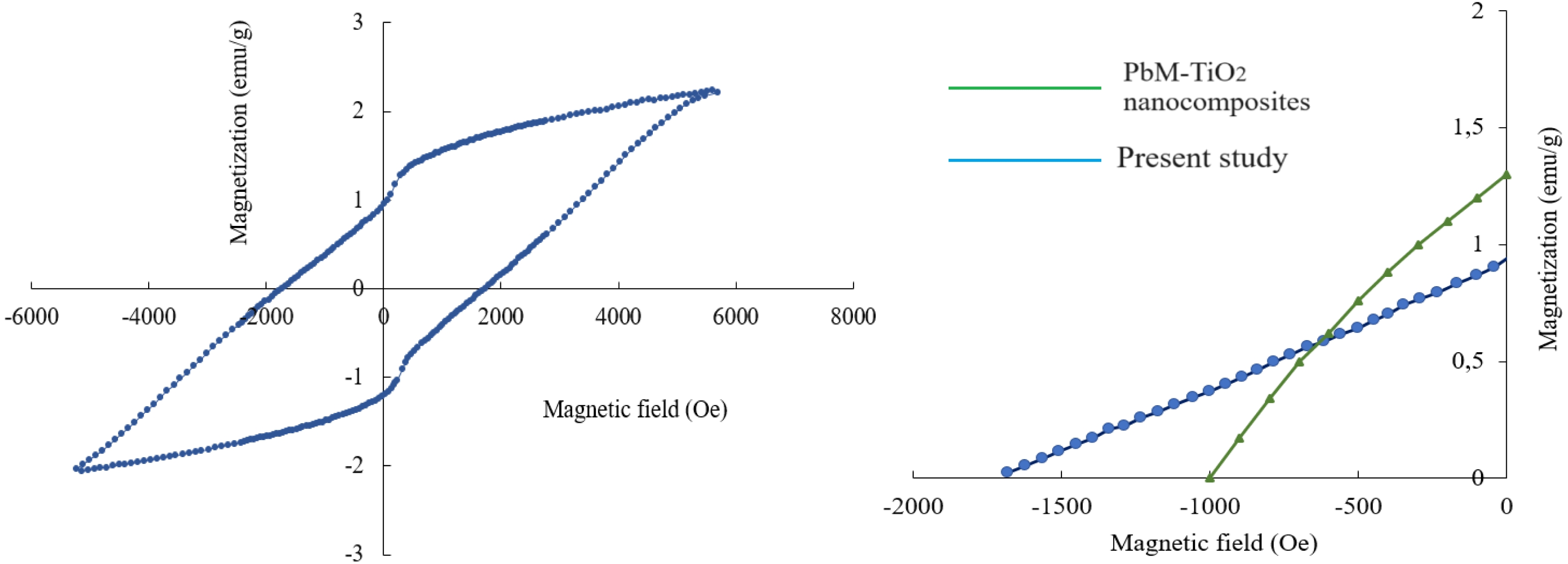
Fig. 5a displays M-H loop for the sample with substitution concentration of x = 0.2 and it was recorded at 26.3 ºC under magnetic field of 5699 Oe. Ms, Mr, Hc and Mr/Ms ratio of the substituted sample were calculated using the magnetic hysteresis curve. According to the obtained M-H curve, the saturation magnetization, Ms of the lead hexaferrite was 2.23 emu/g (Am2/kg) and the remnant magnetization, Mr was 0.94 emu/g (Am2/kg). It can be seen from Fig. 5a. that the magnetic properties (Ms and Mr) decreased in comparison to that of the pure lead hexaferrite sample (Ms = 38.3 emu/g and Mr = 20 emu/g) [54] after the substitution of La-Y. The reduced value of Ms can be explained based on the occupancy of La and Y cations at the different sites of the lattice [55-57]. The obtained hysteresis curve of the Pb-ferrite at RT displayed the hardferrimagneticbehaviour (higher than Hc value of 0.125 kOe). The coercivity (Hc) value that was obtained from the isothermal magnetization curve of the sample was 1.732 kOe (137.9 kA/m). The squareness ratio (Mr/Ms) is a characteristic that is related to the magnetic hardness (high Mr/Ms of 0.48-1.0299) and Mr/Ms values of the multi-domain materials are smaller than 0.5 [45]. In the present study, Mr/Ms value was calculated to be 0.421 as shown in Fig. 5a. This value indicates that the obtained sample possesses the multi-domain structure.
The room-temperature magnetic values in the literature were provided and compared to the present study in Table 2. When the magnetic parameters compared, it was seen that one of the studies indicated a multi-domain structure with a SQR value smaller than 0.5 [8] and the other one had a SQR value equal to the critical value of 0.5 [41]. Fig. 5b. represents the second quadrant of our sample with that of the reference sample, which is PbM-TiO2 nanocomposite [8]. With the help of the second quadrant of the magnetic loop, the maximum energy product (BH)max of our sample was calculated to be 0.031 MGOe (0.25 kJ/m3).
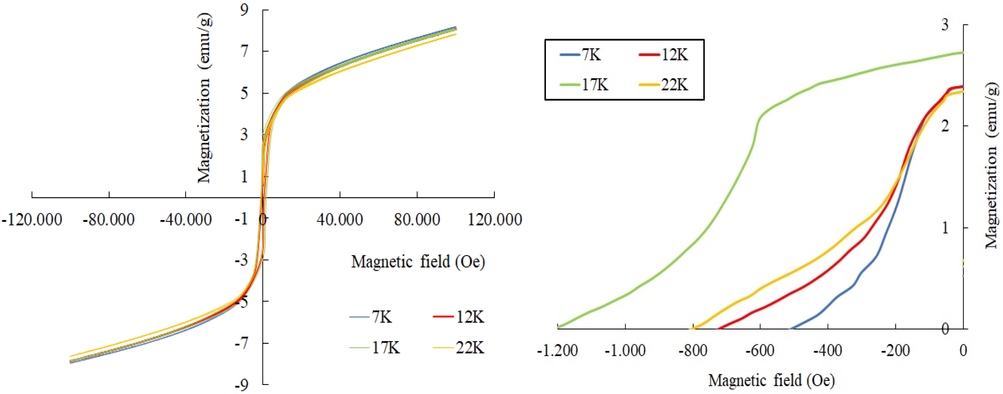
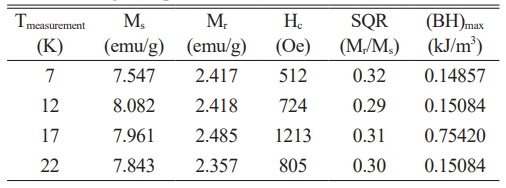
For the samples of PbLa0.1Y0.1Fe11.8O19, the M(H) relationships were also measured at 7 K, 12 K, 17 K and 22 K under the external magnetic field of ± 100 kOe. These curves were presented in Fig. 6. The magnetic parameters of the samples in the range of 7-22 K were deduced from the M(H) curves and were tabulated in Table 3 [55-57].
It was seen that the coercivity, Hc varied between around 0.5 kOe and 1.2 kOe. The remnant magnetization,Mr was in the range of approximately 2.35-2.48 emu/g and Ms varied from 7.5 to 8.08 emu/g in the temperature range of 7-22 K. The obtained results in the range of 7-22 K revealed that the hexaferrites showed a soft magnetic behaviour [58-60].Compared to the room temperature results at 300 K, the magnetization exhibited a noticeable rise in the range of 7-22 K. This rise in the magnetization can be attributed to the reduction in the thermal fluctuations of the magnetic moments [61-64].As the measurement temperature decreased from RT down to 7-22 K, the coercivity, Hc values were reduced. The coercivity reduction with the lower temperature is correlated with the alteration of the Ms values [65, 66]. As the Ms values were improved in the range of 7-22 K -compared to that of RT, Hc values were also diminished [62, 67, 68]. It was also observed that Fe sites which were substituted by La3+ and Y3+ cations affected the magnetic parameters of the hexaferrite samples. The Ms value depended on the replacement of the magnetic Fe3+ cations by the non-magnetic La-Y ions and also, on the preferential site occupancy of them [69-71].If the spin-up sites of 2a, 2b and 12k are occupied by the non-magnetic cations such as La-Y, the net magnetic moment and thus the magnetization value decreases [70, 72];this was the reason why Ms value of the co-substituted sample was reduced compared to the pure lead hexaferrite. In addition, the maximum energy product, (BH)max values over the low temperature range of 7-22 K varied between 0.0185-0.094 MGOe.
|
Fig. 2 XRD pattern of lead hexaferrite sample and slow scan rate pattern. |
|
Fig. 3 a) Plot of polarization (P) vs electric field (E) a) for different voltages at 100Hz; b) for the frequencies of 10, 30, 50 and 100 Hz. |
|
Fig. 4 a) Plot of polarization (P) vs electric field (E) for the frequencies of 100 and 500 Hz; b) Variation of dielectric constant with the frequency. |
|
Fig. 5 a) M-H loop of PbLa0.1Y0.1Fe11.8O19 sample; b) second quadrant with the reference sample. |
|
Fig. 6 M(H) curves for La-Y substituted hexaferrites at 7-22 K. |
|
Table 1 The values obtained from the X-ray diffraction analysis. |
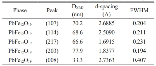
Vcell is unit cell volume; DXRD is average crystallite size |
|
Table 2 RT magnetic parameters of lead hexaferrite samples. |
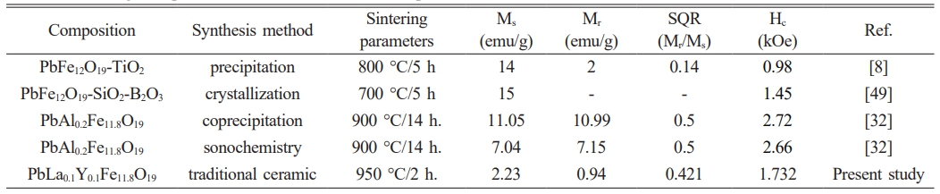
Ms; Saturation magnetization, Mr; Remnant magnetization, Mr/Ms; Squareness ratio, Hc; Coercivity, Ref.; References |
As a result of the experimental work that was carried out, M-type lead hexaferrite with the chemical formula of PbLa0.1Y0.1Fe11.8O19 was successfully produced by the traditional ceramic process where there are relatively lesser number of literature studies among the other M-type hexaferrite materials. From the XRD analysis, it was observed that the primary phase of the sample was identified to be a single M-hexaferrite phase after co-substitution for Fe3+ cations at x = 0.2.
Since the typical hysteresis behaviour was not observed for the polarization curve, our sample did not exhibit the ferroelectric response. According to the elliptical polarization curve, the symmetrical values changed between 0.8 and -0.8 µC/cm2 at the frequency of 5.76 kV. The source of the absence of ferroelectric response is believed to be the crystal structure of PbFe12O19 with space group of P63/mmc with a high symmetry. When the magnetic parameters were evaluated through the M-H measurement, it was found that a clear ferrimagnetic response result was obtained.
A hard magnetic property was obtained at RT with a reduction of Ms value when compared to the unsubstituted lead hexaferrite. The maximum energy product (BHmax) value at RT was calculated as 0.031 MGOe through the second quadrant of the magnetic curve. The maximum saturation magnetization at the low temperature range was found to be 8.08 emu/g, which was measured at 12 K and the coercivity was 1.213 kOe and it was measured at 17K. All of the ferrites characterized at low temperatures were magneticallysoft with the remnant magnetizations smaller than 6.5 emu/g. Based on the findings obtained from this work, it can be concluded that the present data could be useful in the production of Pb-hexaferrite samples for the development of ferrimagnetic properties of ferrite magnets.
The author is grateful to the technical support of the Afyon Kocatepe University. The characterization studies were conducted with the help of Dokuz Eylül University Center for Fabrication and Application of Electronic Materials laboratories, Izmir Institute of Technology Department of Materials Science and Engineering and Ankara UniversityCenter of Excellence for Superconductivity Research.
- 1. Y. Marouani, J. Massoudi, M. Noumi, A. Benali, E. Dhahri, P. Sanguino, M.P.F. Graça, M.A. Valente, and B.F.O. Costa, RSC Adv. 11[3] (2021) 1531-1542.
-

- 2. G.-L. Tan and M. Wang, J. Electroceram. 26[1-4] (2011) 170-174.
-
- 3. R.H. Althomali and S.U. Asif, Inorg. Chem. Commun. 168 (2024) 112956.
-
- 4. J. Mahapatro, S.S. Meena, and S. Agrawal, J. Rare Earths 43[1] (2025) 115-123.
-
- 5. H. M. Umair, I. Bibi, F. Majid, A. Dahshan, S. Kamal, K. Jilani, S. Nouren, Z. Nazer, M. Iqbal, and N. Alwadai, J. Alloy. Compd. 999 (2024) 174893.
-
- 6. J.-Y. You, K.-H. Lee, Y.-M. Kang, and S.-I. Yoo, Appl. Sci. 12[23] (2022) 12295.
-
- 7. R. Liu, L. Wang, Z. Xu, C. Qin, Z. Li, X. Yu, D. Liu, H. Gong, T. Zhao, J. Sun, F. Hu, and B. Shen, Mater. Today Commun. 32 (2022) 103996.
-
- 8. B. Lahijani, K. Hedayati, and M. Goodarzi, Main Group Met. Chem. 41[3-4] (2018) 53-62.
-
- 9. Ch. Rambabu, B. Aruna, P.S.V. Shanmukhi, M.G. Kiran, N. Murali, T.W. Mammo, D. Parajuli, P. Choppara, P. Himakari, and P.V.L. Narayana, Inorg. Chem. Commun. 159 (2024) 111753.
-
- 10. S.K. Godara, Himanshi, R. Jasrotia, V. Kaur, P.S. Malhi, J. Ahmed, A. Kandwal, S. Verma, M. Singh, P. Kaur, R.K. Dhaka, K. Chuchra, A. ul H.S. Rana, A.K. Sood, K. Sharma, S. Dhaka, and A. Verma, J. Magn. Magn. Mater. 573 (2023) 170643.
-
- 11. M. Jamshaid, M.I. Khan, H.M. Khan, A. Rauf, O.P. Kumar, M.N. Akhtar, S. Iqbal, A. Shanableh, and A. ur Rehman, Desalin. Water Treat. 226 (2021) 431-440.
-
- 12. I.V. Lisnevskaya and I.A. Aleksandrova, Nanomater. 10[9] (2020) 1630.
-
- 13. Polarization and Conduction, Resource: MIT Open Course Ware (2001-2024). Accessible through: http://ocw.mit.edu/terms
- 14. M. Thakur, C. Singh, V. Solanki, R.B. Jotania, H. Mahajan, and A.K. Srivastava, Physica B 673 (2024) 415515.
-
- 15. S. Zhou, Y. Yang, R.-Y. Lei, J.-P. Zhou, and X.-M. Chen, J. Magn. Magn. Mater. 539 (2021) 168333.
-
- 16. A.Y. Mironovich, V.G. Kostishin, R.I. Shakirzyanov, A.A. Mukabenov, S.A. Melnikov, A.I. Ril, and H.I. Al-Khafaji, J. Solid State Chem. 316 (2022) 123625.
-
- 17. B. Kaplan, Preparation of PLZT Thin Films By Chemical Solution Deposition and Their Characterization, METU, MSc. thesis, Metallurgical and Materials Engineering, November (2005).
- 18. M. Hashim, S.J. Salih, M.M. Ismail, A. Ahmed, S.S. Meena, A.A. Gaikwad, R.B. Jotania, S. Kumari, D. Ravinderj, R. Kumar, A. Imran, K.M. Batoo, and S.E. Shirsath, Physica B 681 (2024) 415840.
-
- 19. V. Dongquoc, S.-Y. Park, J.-R. Jeong, B.D. Tu, D.T. H. Giang, N.T. Dang, and T.L. Phan, J. Magn. Magn. Mater. 588[Part B] (2023) 171486.
-
- 20. S. Aman, M.N. Ashiq, V.G. Kostishyn, S.V. Trukhanov, and A.V. Trukhanov, J. Magn. Magn. Mater. 564[Part 2] (2022) 170207.
-
- 21. V. Turchenko, A.S. Bondyakov, S. Trukhanov, I. Fina, V.V. Korovushkin, M. Balasoiu, S. Polosan, B. Bozzo, N. Lupu, and A. Trukhanov, J. Alloys Compd. 931 (2023) 167433.
-
- 22. Dielectric Materials, Dissemination of IT for the Promotion of Materials Science (2004-2024). University of Cambridge. Accessible through: https://www.doitpoms.ac.uk/tlplib/dielectrics/variation.php
- 23. M. Arora, S. Kaur, S. Kumar, K. M. Batoo, S. Hussain, A. Sharma, V. Arora, I. Sharma, M. Singh, and A. Singh, Ceram. Int. 50[7] (2024) 10117-10130.
- 24. P. Kaur, V. Kaur, S. Kaur, R. Kaur, M. Sandhu, H. Sarangal, N. Aggarwal, and S.B. Narang, Mater. Today Proc. (2024) In Press, Corrected Proof.
-
- 25. S.T.A. Naqvi, C. Singh, S.K. Godara, R.B. Jotania, P.K. Maji, and C.R. Vaja, Ceram. Int. 50[5] (2024) 7323-7335.
-
- 26. W. Zheng, X. Wang, X. Zhang, B. Chen, H. Suo, Z. Xing, Y. Wang, H.-L. Wei, J. Chen, Y. Guo, and F. Wang, Adv. Mater. 35[21] (2023) 2205410.
-
- 27. M.K. Manglam, L.K. Pradhan, J. Mallick, A. Shukla, S. Kumari, M.K. Yadav, S.N. Rout, and M. Kar, Mater.Today Proc. 66[Part 4] (2022) 1862-1864.
-
- 28. F. Guerrero, E. Govea-Alcaide, P. Marino-Castellanos, Y. Romaguera-Barcelay, J. Anglada, Y. Leyet, A. Almeida, R. Vilarinho, and J. Agostinho-Moreira, Ceram. Int. 46[15] (2020) 23941-23946.
-
- 29. K. Jyotsna and S. Phanjoubam, Mater. Chem. Phys. 317 (2024) 129186.
-
- 30. Y. Yang, X. Liu, S. Feng, X. Kan, Q. Lv, F. Hu, J. Ni, C. Liu, and W. Wang, J. Ceram. Process. Res. 21[4] (2020) 416-424.
-
- 31. J.G. Fisher, P.G. Le, M. Meng, S.H. Heo, T.J. Bak, B.L. Moon, I.S. Park, D.K. Lee, and W.H. Lee, J. Ceram. Process. Res. 19[5] (2018) 434-438.
-
- 32. Y. Yang, X. Liu, S. Feng, Q. Lv, Q. Lv, X. Kan, and R. Zhu, J. Ceram. Process. Res. 21[3] (2020) 378-385.
-
- 33. Y. Yang, M. Wu, F. Wang, J. Shao, and Q. Cao, J. Ceram. Process. Res. 18[7] (2017) 543-549.
-
- 34. Y. Yang, J. Shao, F. Wang, and D. Huang, J. Ceram. Process. Res. 18[6] (2017) 445-450.
-
- 35. Y. Yang, F. Wang, J. Shao, M. Li, and D. Huang, J. Ceram. Process. Res. 18[2] (2017) 151-155.
-
- 36. Y. Yang, J. Shao, and F. Wang, J. Ceram. Process. Res. 18[3] (2017) 242-246.
-
- 37. A. Singh, S.B. Narang, K. Singh, O.P. Pandey, R. and K. Kotnala, J. Ceram. Process. Res. 11[2] (2010) 241-249.
-
- 38. Y. Yang, F. Wang, X. Liu, and J. Shao, J. Ceram. Process. Res. 17[12] (2016) 1249-1253.
-
- 39. G.A. Al-Garalleh, S. H. Mahmood, I. Bsoul and R. Loloe, Mater. Res. Express 7[2] (2020) 026103
-
- 40. S. Prathap, W. Madhuri, and S. S. Meena, Mater. Chem. Phys. 220 (2018) 137-148.
-
- 41. A.D. Suwandi, R. Amalia, E.A. Setiadi, A.P. Tetuko, P. Sebayang, and B. Purnama, J. Phys. Conf. Ser. 1825 (2021) 012043.
-
- 42. M. Mahdiani, A. Sobhani, F. Ansari, and M. Salavati-Niasari, J. Mater. Sci. Mater. Electron. 28 (2017) 17627-17634.
-
- 43. M. Zahid, H.M. Khan, M.A. Assiri, M. Imran, S.A. Buzdar, Mater. Sci. Eng., B 280 (2022) 115707.
-
- 44. F. Ansari, A. Sobhani, and M. Salavati-Niasari, RSC Adv. 4 (2014) 63946-63950.
-
- 45. D. Parmar, P. Dhruv, S. Meena, S. Kavita, C. Singh, M. Ellouze, and R. Jotania, J. Electron. Mater. 49 (2020) 6024-6039.
-
- 46. K.L. Barbalace, Environmental Chemistry (1995-2024). Accessible through: https://environmentalchemistry.com/yogi/periodic/ionicradius.html
- 47. V.E. Zhivulin, E.A. Trofimov, O.V. Zaitseva, D.P. Sherstyuk, N.A. Cherkasova, S.V. Taskaev, D.A. Vinnik, Y.A. Alekhina, N.S. Perov, K.C.B. Naidu, H.I. Elsaeedy, M.U. Khandaker, D.I. Tishkevich, T.I. Zubar, A.V. Trukhanov, and S.V. Trukhanov, iScience 26[7] (2023) 107077.
-
- 48. W. Zheng, X. Wang, X. Zhang, B. Chen, H. Suo, Z. Xing, Y. Wang, H.-L. Wei, J. Chen, Y. Guo, and F. Wang, Adv. Mater. 35[21] (2023) 2205410.
-
- 49. X. Liang, H. Chen, and N.X. Sun, APL Materials 9 (2021) 041114.
-
- 50. L. Jin, F. Li, and S. Zhang, J. Am. Ceram. Soc. 97[1] (2014) 1-27.
-
- 51. S.V. Trukhanov, A.V. Trukhanov, V.A. Turchenko, V.G. Kostishyn, L.V. Panina, I.S. Kazakevich, and A.M. Balagurov, J. Alloy. Compd. 689 (2016) 383-393.
-
- 52. Y. Tokunaga, Y. Kaneko, D. Okuyama, S. Ishiwata, T. Arima, S. Wakimoto, K. Kakurai, Y. Taguchi, and Y. Tokura, Phys. Rev. Lett. 105 (2010) 257201.
-
- 53. G. Tan, X. Chen, J. Magn. Magn. Mater. 327 (2013) 87-90.
-
- 54. A.L. Guerrero-Serrano, M. Mirabal-Garcia, S.A. Palomares-Sanchez, and J.R. Martinez-Mendoza, Rev. Latin Am. Metal. Mat. 34[1] (2014) 136-141.
-
- 55. J. Lee, E.J. Lee, T.-Y. Hwang, J. Kim, and Y.-H. Choa, Sci. Rep. 10 (2020) 15929.
-
- 56. P. Da Silva-Soares, L. da Costa-Catique, F. Guerrero, P. Marinno-Castellanos, E. Govea-Alcaide, Y. Romaguera-Barcelay, A.R. Rodrigues, E. Padron-Hernandez, and R. Pena-Garcia, J. Magn. Magn. Mater. 547 (2022) 168958.
-
- 57. Y.D. Choudhari and K.G. Rewatkar, J. Magn. Magn. Mater. 551 (2022) 169162.
-
- 58. M. Tavoosi, J. Non-Cryst. Solids 615 (2023) 122402.
-
- 59. G.A. Alnawashi, A.M. Alsmadi, I. Bsoul, B. Salameh, G.M. Alzoubi, M. Shatnawi, S.M. Hamasha, and S.H. Mahmood, Results in Phys. 28 (2021) 104574.
-
- 60. Md. Amir, H. Sozeri, A.D. Korkmaz, and A. Baykal, Ceram. Int. 44 (2018) 988-992.
-
- 61. M.A. Almessiere, Y. Slimani, H.S. El Sayed, A. Baykal, and I. Ercan, J. Magn. Magn. Mater. 471 (2019) 124-132.
-
- 62. M.A. Almessiere, Y. Slimani, H. Gungunes, A. Manikandane, and A. Baykal, Results in Phys. 13 (2019) 102166.
-
- 63. M.A. Almessiere, Y. Slimani, and A. Baykal, Ceram. Int. 44 (2018) 9000-9008.
-
- 64. H.C. Fang, C.K. Ong, X.Y. Zhang, Y. Li, X.Z. Wang, and Z. Yang, J. Magn. Magn. Mater. 191 (1999) 277-281.
-
- 65. G. Qiang, Y. Jin, X. Lu, X. Cui, D. Deng, B. Kang, W. Yang, S. Cao, and J. Zhang, Appl. Phys. A 122 (2016) 681.
-
- 66. Y. Slimani, M.A. Almessiere, M. Nawaz, A. Baykal, S. Akhtar, and I. Ercan, Ceram. Int 45 (2019) 6021-6029
-
- 67. M.A. Almessiere, Y. Slimani, H.S. El Sayed, A. Baykal, S. Ali, and I. Ercan, J. Supercond. Nov. Magn. 32 (2018) 1437-1445.
-
- 68. M.H. Shams, A.S. Rozatian, M.H. Yousefi, J. Valicek, and V. Sepelak, J. Magn. Magn. Mater. 399 (2016) 10-18.
-
- 69. R. Topkaya, J. Alloys Compd. 725 (2017) 1230-1237.
-
- 70. R. Topkaya, I. Auwal, and A. Baykal, Ceram. Int. 42 (2016) 16296-16302.
-
- 71. Y.B. Han, J. Sha, L.N. Sun, Q. Tang, Q. Lu, H.X. Jin, D.F. Jin, H.L. Ge, and X.Q. Wang, Int. J. Mod. Phys. B 26 (2012) 1250141.
-
- 72. A. Gonzalez-Angeles, G. Mendoza-Suarez, A. Gruskova, M. Papanova, and J. Slama, Mater. Lett. 59 (2005) 26-31.
-
 This Article
-
2025; 26(6): 1122-1130
Published on Dec 31, 2025
- 10.36410/jcpr.2025.26.6.1122
- Received on Jan 13, 2025
- Revised on Nov 6, 2025
- Accepted on Nov 6, 2025
Services
- Abstract
introduction
material method
research findings and discussion
conclusion
- Acknowledgements
- References
- Full Text PDF
Shared
Correspondence to
- Burcu Ertuğ
-
aBilgi University, Faculty of Engineering and Natural Sciences, 34060 Istanbul, Turkey
Tel : +90-212-3115000 - E-mail: burcuertug@gmail.com
Clean-Energy Research Institute(CRI), Hanyang University, 222, Wangsimni-ro, Seongdong-gu, Seoul, 04763, Korea
E-mail: jcpr@hanyang.ac.kr