


- Preparation and performance of cordierite-mullite saggars with excellent corrosion resistance
Jianjian Duana, Hongfang Shena,b,c,*, Xiao Zhanga,b,c, Zhiqing Wana and Youjun Lua,b,c,*
aSchool of Materials Science & Engineering, North Minzu University, Yinchuan 750021, China
bNational and Local Joint Engineering Research Center for Carbon-based Advanced Ceramic Preparation Technologies, Yinchuan 750021, China
cKey Laboratory for Power Materials and Special Ceramics, Yinchuan 750021, ChinaThis article is an open access article distributed under the terms of the Creative Commons Attribution Non-Commercial License (http://creativecommons.org/licenses/by-nc/4.0) which permits unrestricted non-commercial use, distribution, and reproduction in any medium, provided the original work is properly cited.
The study aims to enhance the corrosion resistance of saggars used as sintering containers for lithium battery cathode materials. Under the typical sintering conditions, saggars undergo severe degradation due to lithium-ion corrosion, manifesting as surface spalling, slag formation, and structural fractures that ultimately lead to saggar failure. To mitigate these issues, we developed mullite-cordierite composite crucibles using an optimized formulation: coarse mullite particles (size from 1.18 to 0.6 mm) as the primary aggregate, combined with a matrix consisting of fine mullite (approximately 0.074 mm), cordierite (approximately 0.074 mm), calcined alumina (approximately 0.044 mm), Foshan yellow clay (approximately 0.044 mm), and coal gangue (approximately 0.044 mm). The effects of sintering temperature on phase evolution and microstructural development of saggar samples were systematically investigated, with parallel evaluation of their physical, mechanical, and corrosion-resistant properties. The optimal performance was achieved at a sintering temperature of 1380 °C for 3 hours, yielding saggars with a bulk density of 2.13 g·cm-3 and a room temperature flexural strength of 10.26 MPa. These samples exhibited exceptional thermal shock resistance, maintaining 50% of their original strength after three thermal cycling tests. Additionally, increasing the content of coarse mullite particles (sizes from 1.18 to 0.6 mm) significantly improved the corrosion resistance of the saggars, as evidenced by the limited reaction layer thickness of merely 520 µm following 34 corrosion cycles.
Keywords: Mullite-cordierite, Refractoriness, Volumetric stability, Thermal shock resistance, Corrosion resistance.
Among lithium battery cathode materials, Li(NixCoyMnz)O2 (LNCM) has undergone significant advancements in recent years. Currently, commercial materials for producing LNCM include lithium cobalt oxide (LiCoO₂), lithium manganate (LiMn₂O₄), lithium iron phosphate (LiFePO₄), and lithium nickel cobalt manganate (LiNiₓCoᵧMn₂O₂) [1]. Compared to LiFePO₄, LiCoO₂, and LiMn₂O₄, nickel-cobalt-manganese (NCM) ternary cathode materials exhibit higher energy density, extended cycle life, enhanced safety, and lower costs [2, 3], making them widely adopted in electric vehicles, communications, and military applications. Saggars primarily serve as crucial containers for lithium battery cathode materials in the high-temperature sintering process, protecting them from contamination [4]. However, during recycling, lithium the penetration and corrosion within the cathode materials can degrade the saggar’s structural integrity, leading to surface spalling, cracking and even failure [5-7].
Recent research has focused on understanding saggar composition and corrosion mechanisms to mitigate contamination during high-temperature cathode synthesis and improve saggar durability [8]. Duan et al. [9] explored the corrosion behavior of cordierite (Mg₂Al₄Si₅O₁₈)-mullite (3Al₂O₃·2SiO₂) and SiC refractories exposed to lithium-ion ternary cathode materials at 1450 °C for 20 hours. Their findings indicated that cordierite-mullite refractories reacted with Li2O, NiO, CoO, and MnO components, generating various products including (Mg, Ni, Co, Mn)Al2O4 compounds and Al2O3-SiO2-based compounds that compromised structural integrity of the material. In the case of SiC refractories, the oxidation reaction of SiC produced SiO2 which subsequently reacted with Li2O to create a lithium silicate compound; while bulk degradation occurred through Li₂O infiltration from the battery cathode material. Gan et al. [10] prepared hibonite-cordierite saggars by incorporating cordierite, zircon, and α-Al2O3 with hibonite (CaAl₁₂O₁₉) known for its alkali resistance. The optimal saggar formulation sintered at 1380 °C exhibited balanced physical properties, microstructure, and mechanical performance. Corrosion testing revealed the formation of calcium feldspars at hibonite grain boundaries, which enhanced corrosion resistance through their stable alkali-resistant properties. Xiang et al. [11] investigated how sintering temperature, cathode material Li(NixCoyMn1-x-y)O2 content, and thermal cycling affect mullite saggar degradation. Their findings revealed that the depth of saggar corrosion increased with higher cathode material loading, elevated sintering temperatures, and increased thermal cycles. The interaction between Li2O generated during the cathode material sintering, and mullite saggars produced LiAlO2 and LiAlSiO4 phases, whose coefficients of thermal expansion differ from that of the saggar, thereby generating microcracks. These cracks expanded rapidly under thermal cycles, ultimately leading to surface spalling and structural failure of the saggar.
Cordierite (Mg₂Al₄Si₅O₁₈) demonstrates multiple advantageous properties including excellent thermal stability, low coefficient of thermal expansion, high electrical resistivity, and cost-efficiency [12-14]. However, its applications are hindered by inherent limitations in mechanical strength and chemical resistance [15-17]. In contrast, mullite (3Al₂O₃·2SiO₂) exhibits favorable chemical resistance, high creep resistance, excellent high-temperature stability, enhanced mechanical strength [18-20] and high thermal shock resistance. To capitalize on these complementary characteristics, mullite-cordierite composite materials have been engineered through strategic phase combination. These composites integrate the low thermal expansion of cordierite with the mechanical robustness and chemical stability of mullite by boasting high thermal conductivity, robust mechanical strength, and superior thermal shock resistance, making them particularly suitable for demanding refractory applications such as kiln furniture and high-temperature containment systems [21-25].
To overcome the challenges of inadequate corrosion resistance and limited-service life associated with the saggars used for sintering LiNixCoyMnzO2 cathode materials, we have developed an optimized mullite-cordierite saggar. The material design employs coarse-grained mullite (1.18-0.6 mm particle size) as the primary aggregate, combined with a fine-grained matrix of cordierite, calcined alumina (α-Al₂O₃), Foshan yellow clay, and coal gangue. This formulation was processed at reduced calcination temperatures to enhance phase stability while maintaining mechanical integrity. The saggar’s corrosion behavior was evaluated under realistic cathode synthesis conditions (850 °C for 10 hours) during solid-state preparation of Li₂Ni₀.₅Co₀.₂Mn₀.₃Oₓ cathode material [26, 27], using an embedded corrosion method. A multi-technique characterization approach was implemented to assess the degradation mechanisms: phase analysis, mechanical testing, and microstructural characterization.
Raw Materials and Saggar Preparation
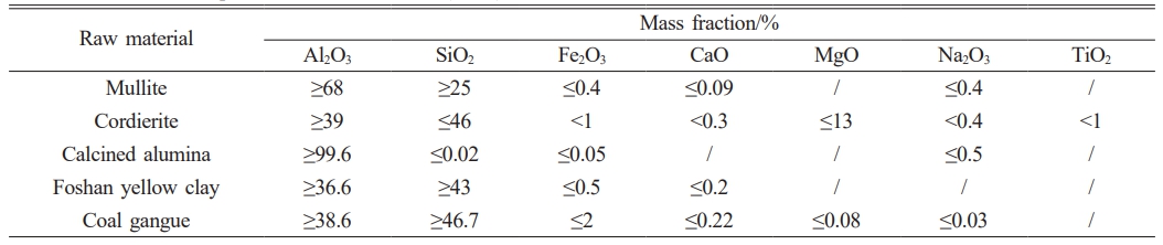
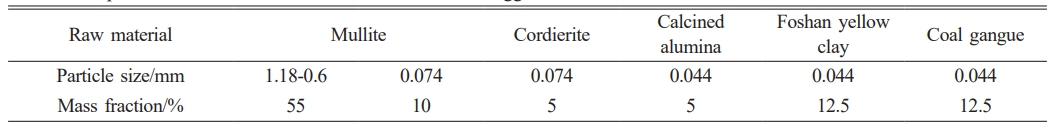
The raw materials used in this study consisted of: mullite particles in two size fractions (coarse: 1.18-0.6 mm; fine: ~0.074 mm), cordierite (~0.074 mm), calcined alumina (~0.044 mm), Foshan yellow clay (~0.044 mm) and coal gangue (~0.044 mm). All ceramic raw materials were sourced from Ningxia Jingyuanda New Material Technology Co., Ltd. (China). Industrial dextrin and deionized water were employed as processing aids. The chemical composition of the raw materials and the detailed experimental formulation of the mullite-cordierite composite are presented in Tables 1 and 2, respectively.
The mullite-cordierite saggars were prepared through a multi-step processing route. First, mullite aggregates (3 wt.%) were homogenized with deionized water. Subsequently, a matrix formulation comprising mullite, cordierite, calcined alumina, Foshan yellow clay, coal gangue, and industrial dextrin was similarly mixed with deionized water. The aggregate and matrix were then blended, sealed, and aged at 25 °C for 24 hours. For saggar samples used for mechanical evaluation, the aged mixture was pressed into rectangular blocks (25 mm × 25 mm × 125 mm) under120 MPa pressure. These green bodies were dried at 110 °C for 24 hours, followed by sintering in a high-temperature resistance furnace at varying temperatures (1320 °C, 1350 °C, 1380 °C, and 1410 °C) for 3 hours, then naturally cooled to room temperature (25 °C). For corrosion testing, the same aged mixture was also pressed into smaller blocks (20 mm × 20 mm × 8 mm), dried under identical conditions (110°C, 24 hours), and sintered at 1380 °C for 3 hours to produce saggar samples specifically for corrosion test.
Material Characterization and Mechanical Property Evaluation
The phase composition of the saggar samples was examined utilizing an XRD-6000 X-ray diffractometer (Shimadzu Co., Japan) with Cu Kα radiation (λ = 1.5406 Å). Scans were performed from 5° to 85° at a rate of 2°·min⁻¹. The subsequent XRD analysis was conducted using MDI Jade 6. Microstructural characterization of the saggar samples was performed using a TM4000Plusll scanning electron microscope (Hitachi Co., Japan) for morphological analysis, and an energy-dispersive X-ray spectrometer (SIGMA 500, Zeiss Co., Germany) for elemental microanalysis.
Dimensional changes during sintering were quantified by measuring sample dimensions before and after firing. Bulk density and apparent porosity were determined using an XF-120S electronic densitometer (Shanghai Li-Chen Bangxi Instrument Technology Co., Ltd., China). Flexural strength was measured via the three-point bending (100 mm span) on a UTM5000 universal testing machine (Shenzhen Sansi Instrument Manufacturing Co., Ltd., China).
Thermal shock behavior was evaluated using an SX2-10-13 muffle furnace (Shenyang Energy Saving Electric Furnace Factory, China) with the following protocol: heating samples to 900 °C (30 min dwell); quenching them in flowing water (16-20 °C, 10 min); surface drying and wiping the samples with a clean cloth; air cooling (5 min); and completing three thermal shock cycles. Residual strength measurements after cycling indicated the thermal shock resistance, expressed as percentage strength retention.
Corrosion Resistance Test
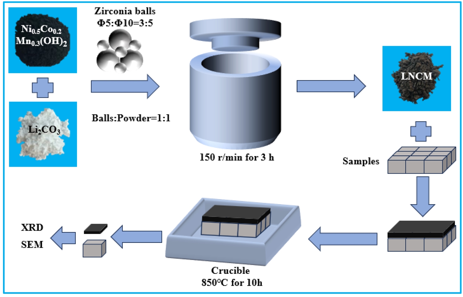
The LNCM precursor used for the corrosion resistance test was prepared by mixing commercially available Li2CO3 (≥99.9 % purity) and Ni0.5Co0.2Mn0.3(OH)2 (≥99.6 % purity) powders in a 30:70 mass ratio. The mixture was homogenized in a rotary mill using zirconia grinding balls (Φ5 mm and Φ10 mm) for 180 minutes. The ball-to-powder mass ratio was maintained at 1:1, with a specific ratio of 3:5 between Φ5 mm and Φ10 mm zirconia balls. Fig. 1 illustrates the corrosion testing procedure for sintered samples. Small saggar blocks were first positioned within a crucible, followed by the uniform application of a 5 mm thick layer of LNCM precursor powder on top of each block. The crucible assembly was then heated in a high-temperature furnace at 850 °C for 10 hours to simulate corrosion conditions. After completing three corrosion cycles, the saggar blocks were extracted from the crucible, and residual LNCM precursor material was carefully removed from their surfaces to facilitate phase composition analysis. For microstructural characterization, the corroded saggar blocks were vacuum-impregnated with low-viscosity epoxy resin and allowed to cure completely. The resulting blocks were subsequently assessed using scanning electron microscopy (SEM) and energy-dispersive spectroscopy (EDS) to determine the corrosion layer thickness and analyze the morphological changes induced by the LNCM interaction.
|
Fig. 1 Corrosion test procedure for sintered saggar blocks. |
XRD Analysis
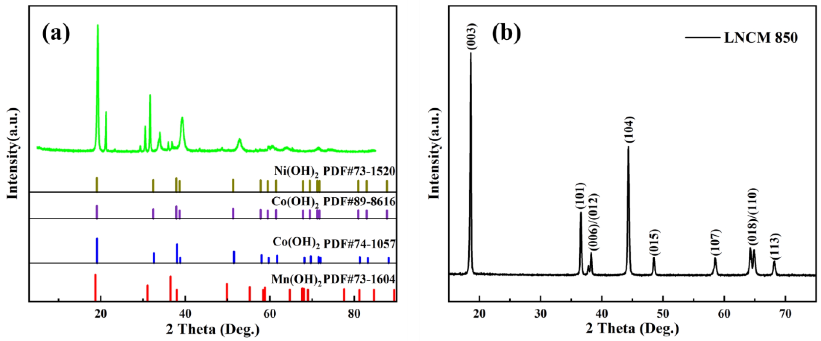
Fig. 2 shows the XRD patterns of LNCM precursors before (a) and after (b) heating. The diffraction analysis confirms the successful synthesis of LNCM lithium-ion cathode material via solid-state reaction at 850 °C for 10 hours, as evidenced by the complete transformation of precursor phases into the characteristic LNCM crystal structure [26, 27].
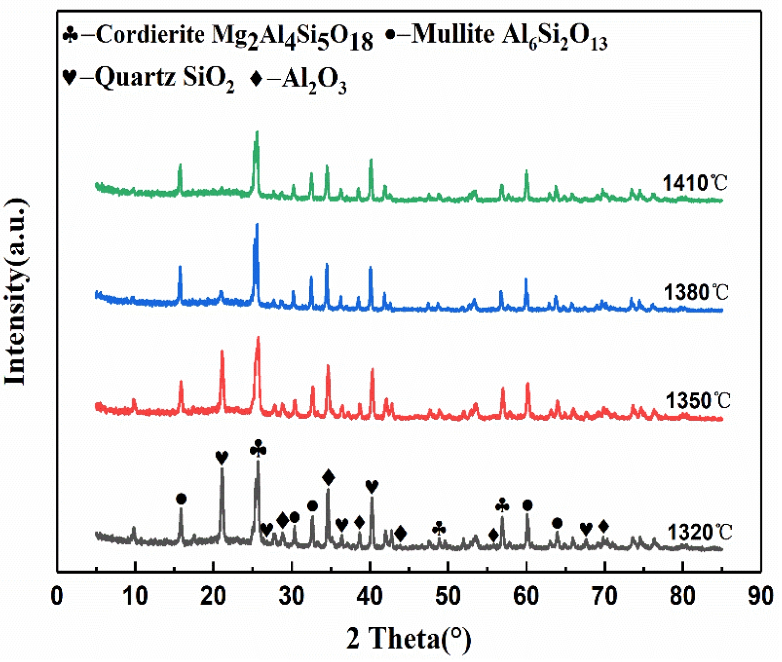
Fig. 3 presents the XRD patterns of the saggar blocks sintered at various temperatures. In the temperature range of 1320 to 1380 °C, the primary crystalline phases consist of cordierite (Mg2Al4Si5O18), mullite (Al6Si2O13), corundum (Al2O3), and silica (SiO2). The absence of diffraction peaks corresponding to Foshan yellow clay and coal gangue confirms the complete decomposition of the kaolinite in the clay [28]. The diffraction patterns reveal systematic phase transformations with increasing temperature: the peak intensities of SiO2 and Al2O3 gradually decrease while those of cordierite and mullite increase. This is attributed to the liquid-phase reaction of SiO2 and Al2O3, forming mullite and cordierite (Equations 1 and 2) [28]. At 1410 °C, the diffraction peaks of SiO2 disappear completely, accompanied by reduced intensity in the diffraction peaks for mullite, cordierite, and corundum. This phenomenon occurs because trace oxides (CaO, Fe₂O₃, TiO₂) lower the system’s eutectic point, promoting liquid phase formation that diminishes the crystallinity of the primary phases [29].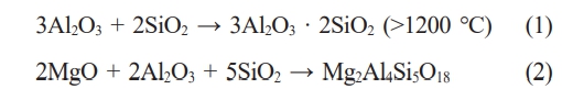
Physical Properties
Micromorphology
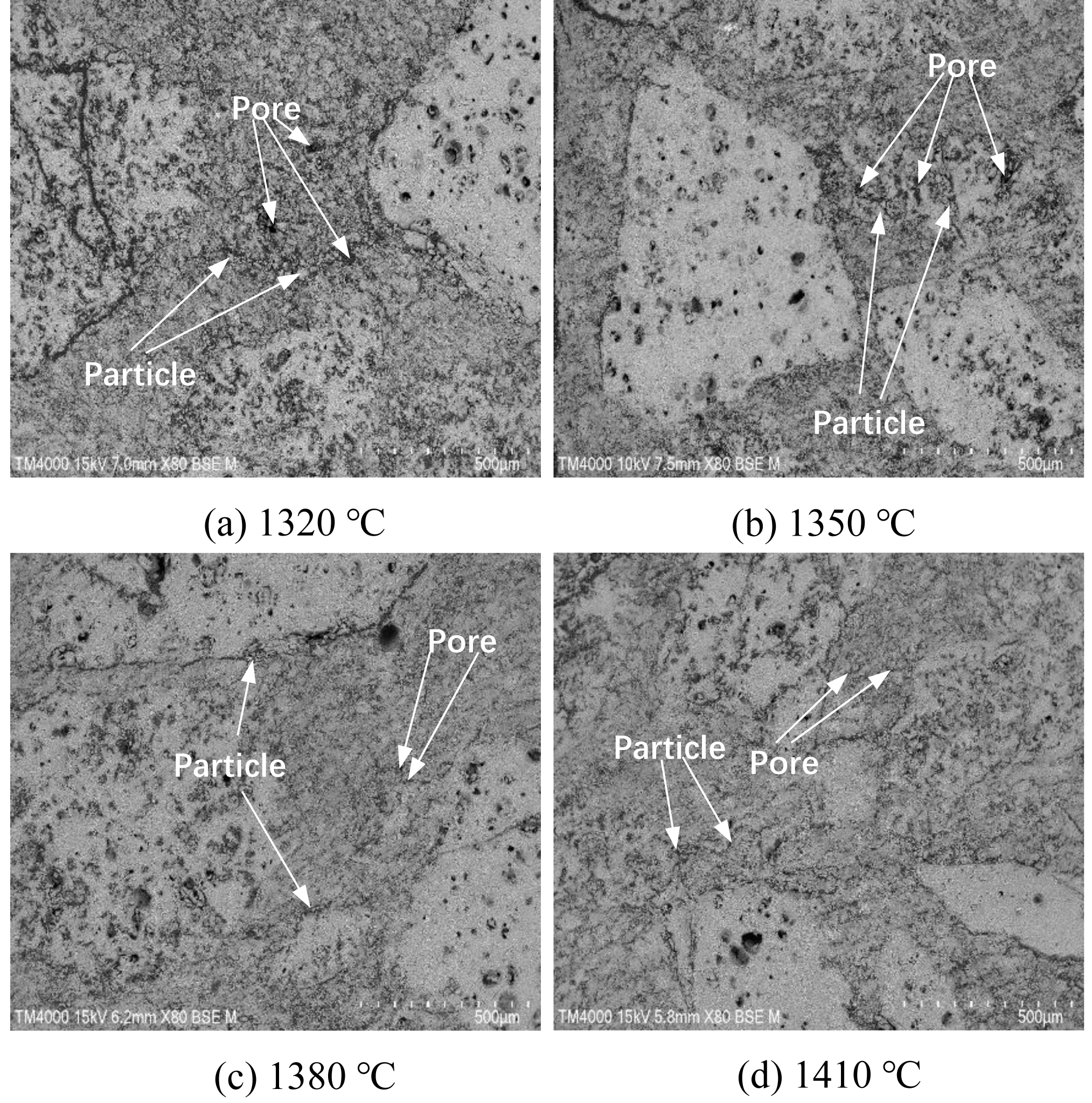
Fig. 5 presents SEM images illustrating the morphological evolution of saggar blocks sintered at different temperatures. For blocks sintered at lower sintering temperatures (1320 °C to 1350 °C), the microstructure consists of numerous discrete particles with distinct boundaries and irregular pore distribution, exhibiting weak interparticle connectivity. The interface between matrix and aggregate phases remains clearly visible under these conditions. As the sintering temperature increases to 1380 °C and 1410 °C, significant microstructural changes occur: individual particle boundaries become less defined, pore size and quantity decrease substantially, and matrix-aggregate interfaces grow increasingly diffuse. These transformations are ascribed to the progressive generation of the liquid phase at elevated temperatures, which facilities three processes: faster ion diffusion, improved mass transfer between phases, and accelerated particle rearrangement. The liquid phase progressively fills interparticle voids, leading to denser microstructural packing and stronger interfacial bonding [30]. The phase analysis (Fig. 3) displays corresponding intensification and sharpening of the diffraction peaks of cordierite and mullite phases with increasing temperature. This correlation suggests a progressive grain growth and crystallinity improvement, where expanding grain boundary regions facilitate pore migration and elimination. The combined effects of liquid phase sintering and grain boundary development ultimately yield a more homogeneous microstructure with enhanced matrix-aggregate cohesion.
Mechanical Properties
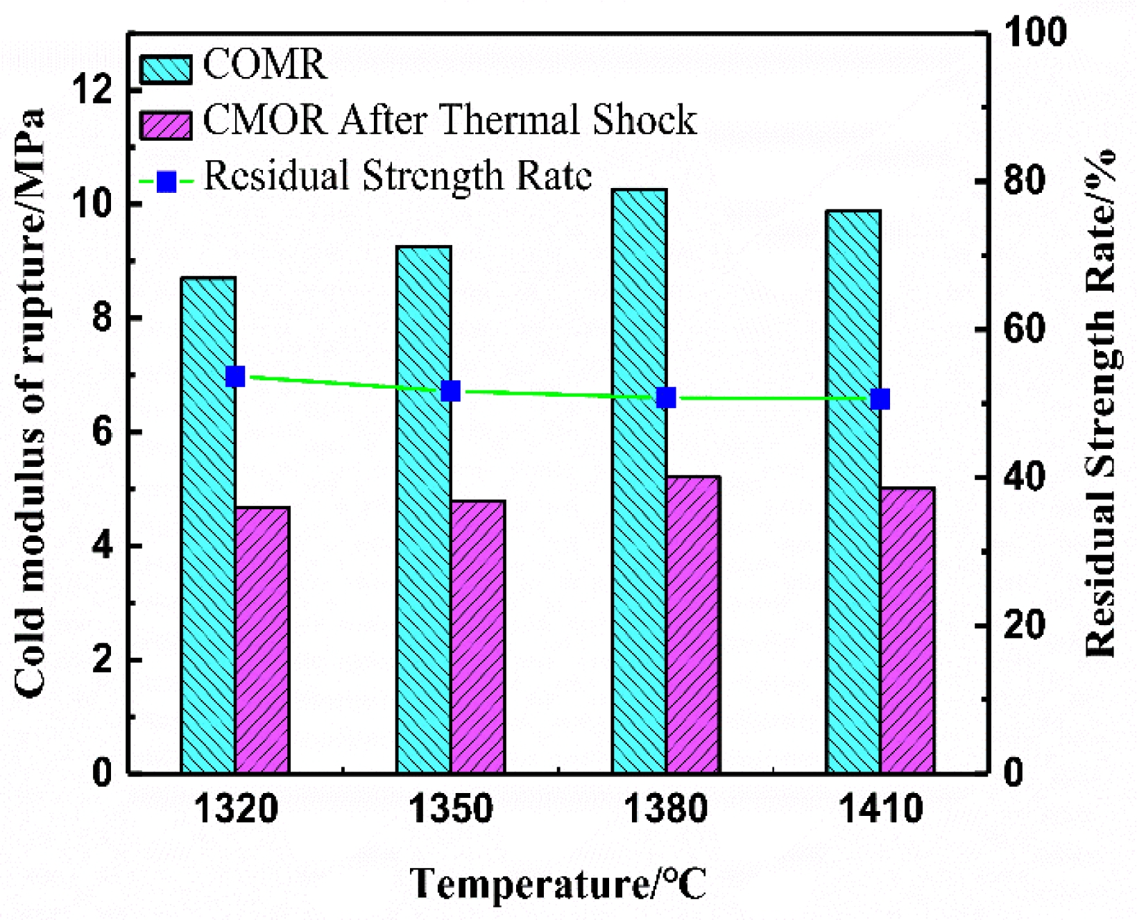
Fig. 6 shows the room-temperature flexural strength (CMOR), residual strength, and residual strength retention of saggar blocks sintered at different temperatures. The data reveal a consistent trend where all three mechanical parameters initially increase then decrease with rising sintering temperature. Specifically, the optimal performance occurs in blocks sintered at 1380 °C, demonstrating a room-temperature flexural strength of 10.26 MPa and residual strength of 5.21 MPa after three thermal shock cycles. Across the tested temperature range, strength retention values remain stable between 51% and 53% following thermal cycling. The thermal shock resistance, a critical factor determining saggar service life, primarily depends on the thermal expansion characteristics of the aggregate. These further emphasize the importance of both aggregate selection and formulation composition in achieving optimal material performance. The block sintered at 1380 °C, with the optimum comprehensive performance, was selected for subsequent corrosion resistance evaluation.
Corrosion Resistance
Post-Corrasion Surface Analysis
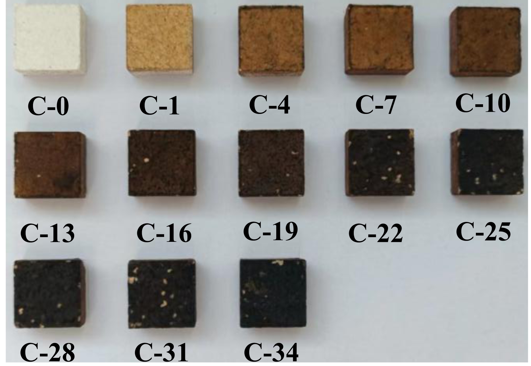
Fig. 7 presents the surface morphological characteristics of saggar blocks sintered at 1380 ℃ for 3 hours following exposure to varying corrosion cycles. The micrographs reveal two distinct degradation trends with increasing cycle count: (1) progressive darkening of surface coloration and (2) intensification of surface spalling.
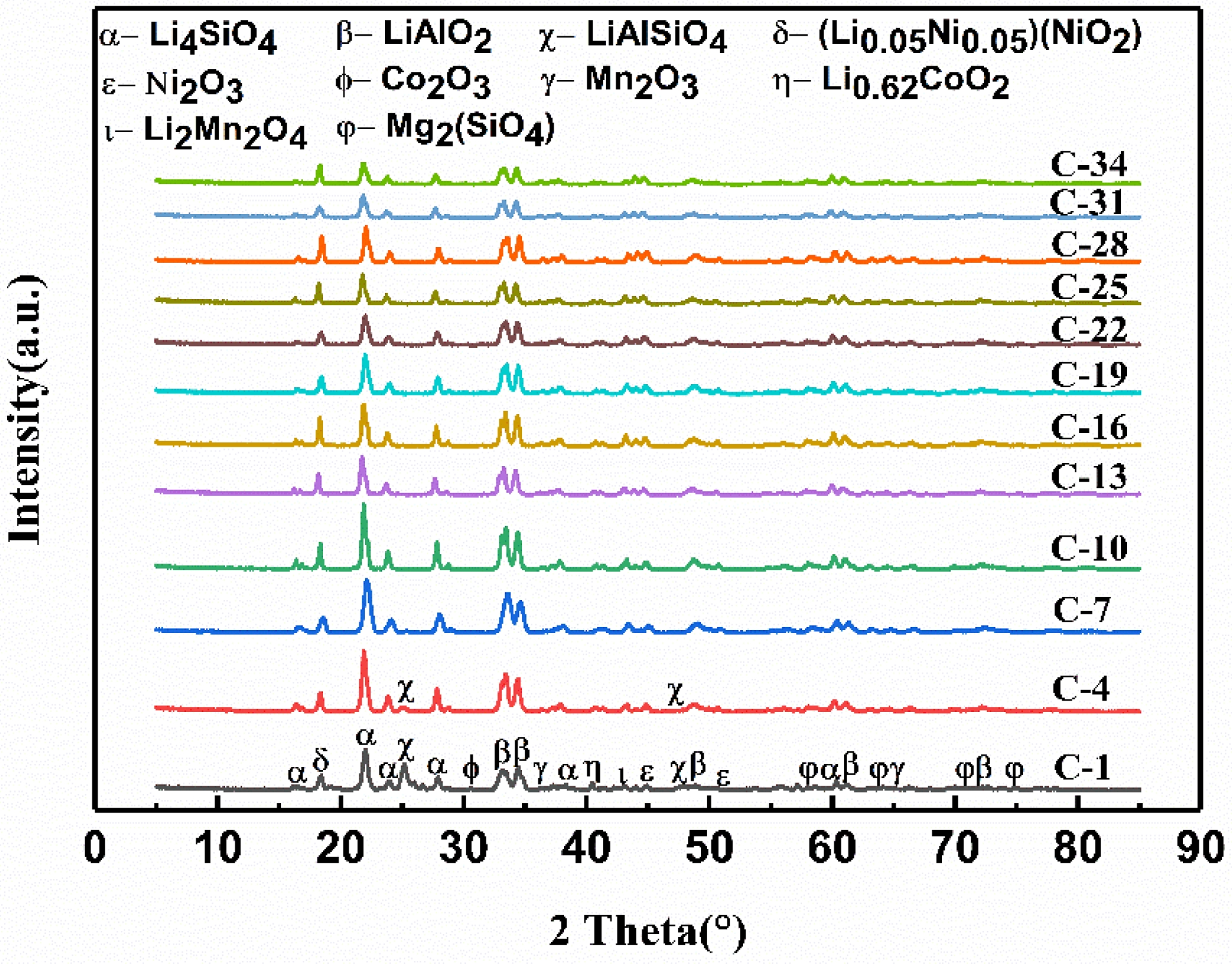
Fig. 8 presents the XRD patterns showing the surface phase evolution of saggar blocks sintered at 1380 °C for 3 hours and subsequently subjected to multiple corrosion cycles (850 °C for 10 hours per cycle). The analysis covers corrosion cycles ranging from 1 (C-1) to 34 (C-34). Across all cycles, the saggar surface consistently contained multiple reaction products including lithium nickel oxide (Li0.05Ni0.05(NiO2)), lithium manganese oxide (Li2Mn2O4), lithium-cobalt oxide (Li0.62CoO2), manganese trioxide (Mn2O3), nickel trioxide (Ni2O3), cobalt trioxide (Co2O3), lithium aluminate (LiAlO2), lithium silicate (Li4SiO4), and magnesium silicate (Mg2SiO4) phases. Notably, Li0.05Ni0.05(NiO2) is the primary product of the cathode material synthesis process. The presence of lithium-containing phases (LiAlO₂, LiAlSiO₄, and Li₄SiO₄) confirms chemical interaction between the saggar material and Li₂Ni₀.₅Co₀.₂Mn₀.₃Oₓ, as the original saggar composition lacked lithium. A clear transition occurs at seven corrosion cycles: characteristic while LiAlSiO4 diffraction peaks are clearly visible in samples subjected to fewer than seven cycles corrosion, these diffraction peaks are no longer detectable in samples subjected to more corrosion cycles.
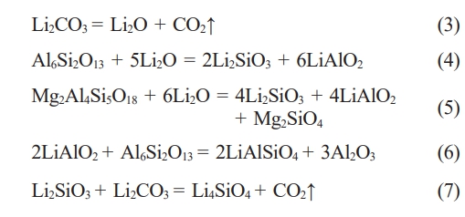
The entire corrosion process involves several possible reactions, beginning with the thermal decomposition of Li2CO3 to yield Li2O (Eq. 3) [31]. This Li2O subsequently reacts with the mullite matrix (Al6Si2O13) resulting lithium silicate (Li2SiO3) and lithium aluminate (LiAlO2) (Eq. 4) [9]. Parallel reaction pathways involve the interaction of Li₂O with cordierite (Mg₂Al₄Si₅O₁₈), yielding additional Li₂SiO₃ and LiAlO₂ along with magnesium silicate (Mg2SiO4) (Eq. 5) [9]. The corrosion process continues through secondary reactions, where the initially formed LiAlO2 subsequently reacts with residual mullite to form lithium aluminum silicate (LiAlSiO4) and alumina (Al2O3) (Eq. 6) [11]. Furthermore, Li2SiO3 combines with remaining Li2CO3 to produce lithium orthosilicate (Li4SiO4) (Eq. 7) [9].
Morphology and Elemental Distribution after Corrosion
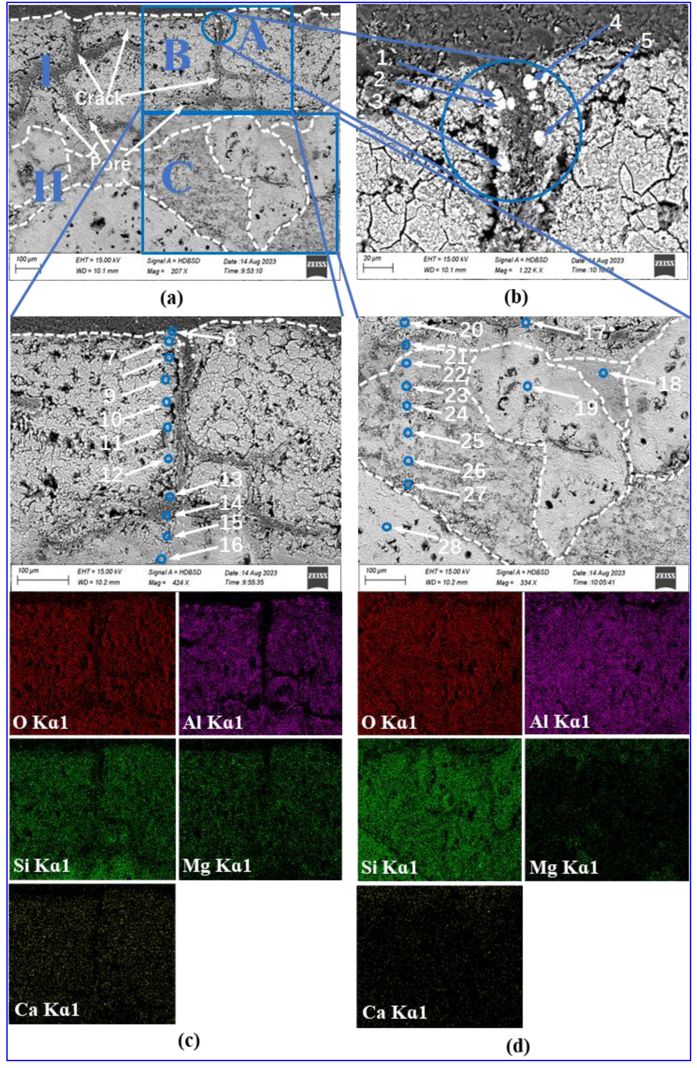
Fig. 9(a) presents SEM images of the interfacial region in saggar blocks subjected to 34 corrosion cycles, revealing distinct morphological differences between two layers. Layer I, the reaction zone formed through chemical interaction between LNCM and saggar material, exhibits a porous, loosely packed structure. Layer II maintains greater structural integrity, consisting primarily of mullite particles embedded in a dense matrix.
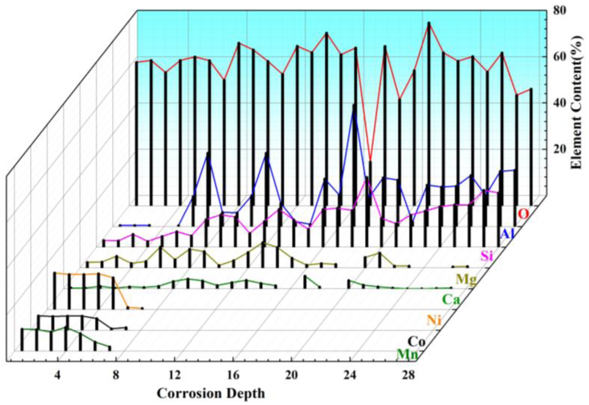
Higher magnification analysis of selected regions shown in Fig. 9(b), (c), and (d) provides detailed microstructural information. The Point A in Layer I as shown in Fig. 9(b) contains white granular deposits along crack boundaries, with EDS analysis (Fig. 10, points 1-5) confirming these as LiNixCoyMnzO2. In Fig. 9(c), Point B in Layer I show reduced cathode material adhesion and increased crack density, featuring both transverse and longitudinal cracks along with intricate microcracks. These observations can be explained by the thermal cycling inherent in the firing process. The volumetric changes caused by the formation of new phases generate internal stresses that ultimately lead to crack initiation, surface spalling, and reaction layer detachment. EDS elemental mapping confirms the absence of Ni, Co, Mn in the primary composition of the reaction layer. Further EDS scanning at points 6 and 7 (see Figure 10) indicates a small amount of Ni, Co, Mn with concentrations decreasing significantly beyond point 8. This elemental distribution pattern, when correlated with XRD data (Fig. 8) suggests that the transition metal (Ni, Co, Mn) penetration during corrosion is both limited in extent and shallow in depth. Coupled with Eqs. (4) to (8), this observed behavior identifies Li2O as the primary agent responsible for saggar corrosion. The high diffusivity of Li2O allows for its rapid reaction with Al6Si2O13 and Mg2Al4Si5O18 phases in the saggar material. As these reactions progress, the formation of lithium-containing phases (LiAlO₂, LiAlSiO₄, and Li₄SiO₄) dominates the corrosion products. Fig. 9(d) shows a high-magnification view of point C within Layer II, revealing significantly reduced porosity and crack density compared to Layer I. The interface between the two layers exhibits a gradual transition, with the intermediate region appropriately classified as the matrix component of Layer II. Phase composition analysis (Fig. 8) indicates that Layer II mainly comprises granular mullite of varying sizes, embedded within a continuous matrix of corundum and cordierite. EDS point analysis at points 19 and 28 demonstrates the absence of Mg, providing definitive evidence that the coarse particulate phase consists exclusively of mullite.
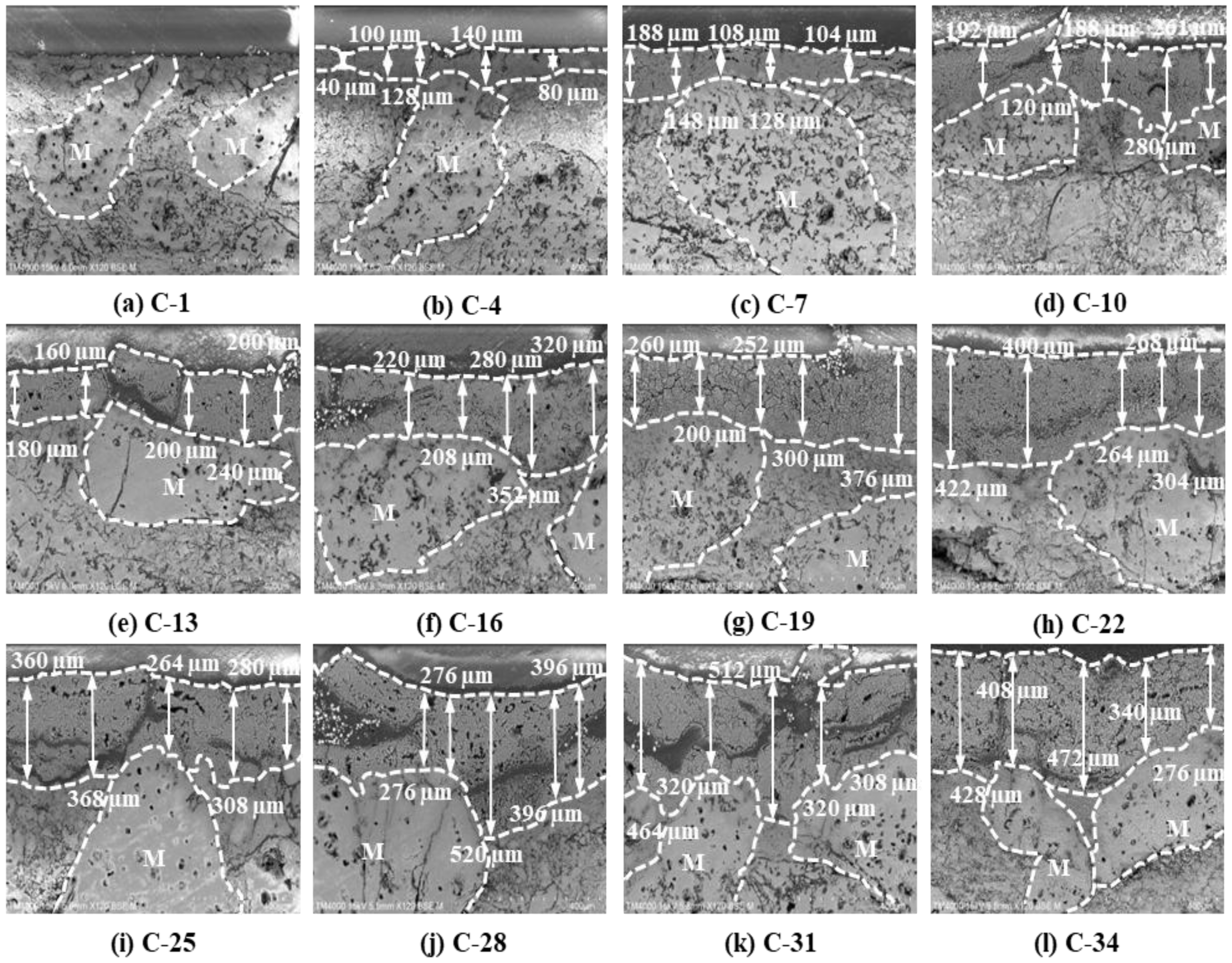
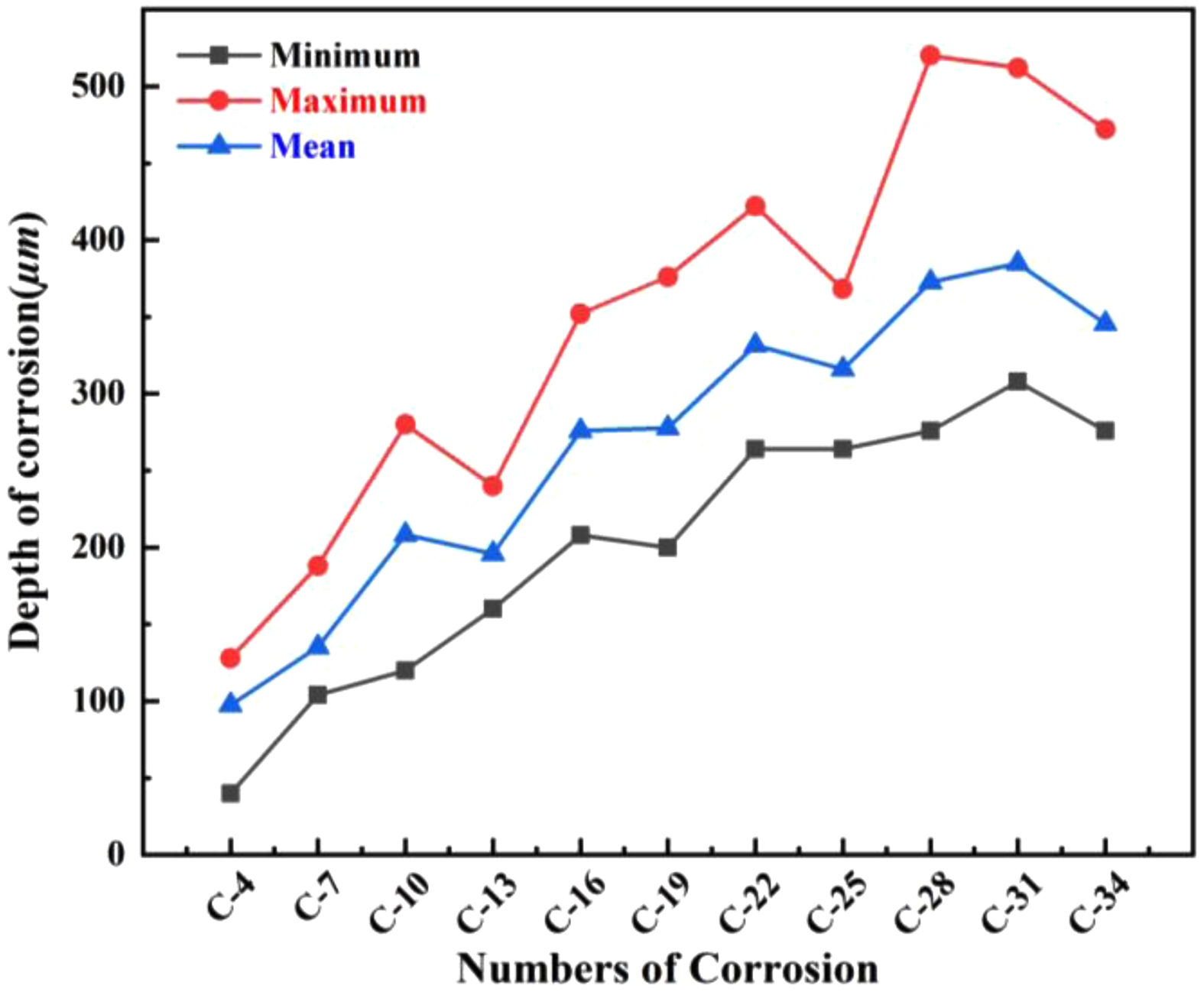
The morphological evolution (Fig. 11) and corrosion depth measurements (Fig. 12) for saggar blocks subjected to varying corrosion cycles demonstrate a progressive increase in reaction layer thickness with extended corrosion exposure. Specifically, the average reaction layer thickness shows consistent growth with increasing corrosion cycles; both maximum and minimum thickness measurements follow an upward trend; and after 34 corrosion cycles, the maximum penetration depth reaches 520 µm. Notably, regions containing coarse mullite particles (1.18 to 0.6 mm) exhibit significantly reduced corrosion thickness compared to coarse-particle-free zones throughout the entire testing period (0-34 cycles). This enhanced resistance correlates with the aggregate’s superior bulk density and reduced apparent porosity. The coarse mullite phase effectively retards cathode material corrosion, suggesting that optimizing the coarse particle content could improve saggar performance in practical applications.
|
Fig. 2 XRD patterns of LNCM precursors before (a) and after (b) calcination at 850 °C for 10 hours. |
|
Fig. 3 XRD patterns of saggar blocks sintered at different temperatures for 3 hours. |
|
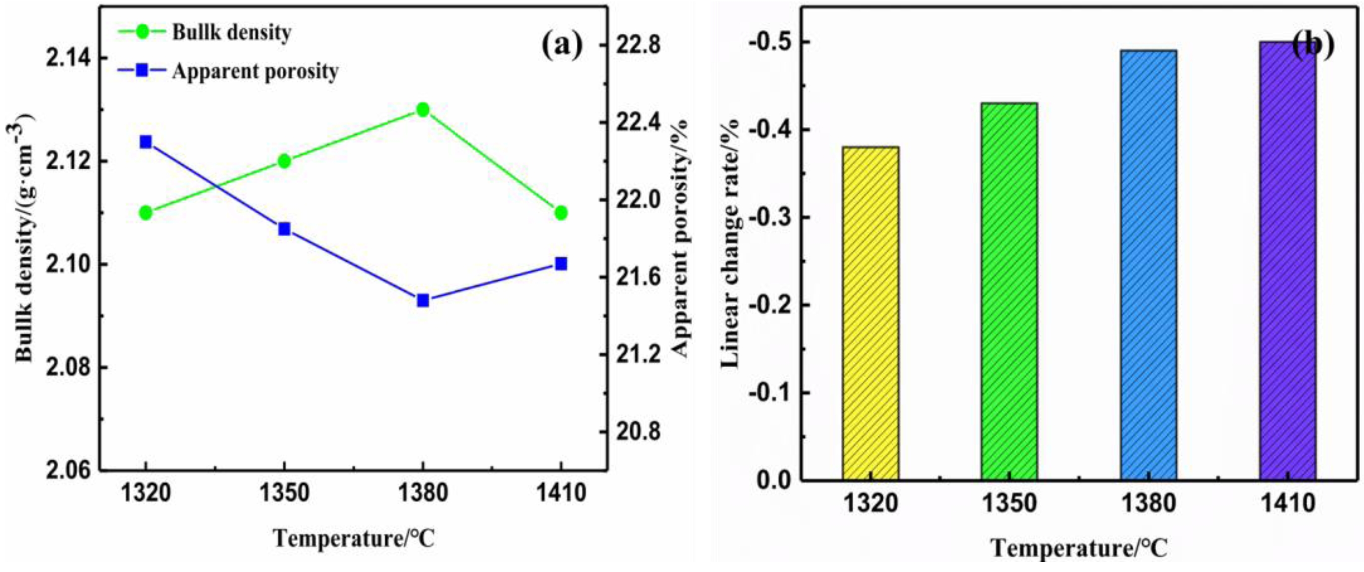
Fig. 4 Bulk density and apparent porosity (a) and linear change rate (b) of saggar blocks sintered at different temperatures for 3 hours. |
|
Fig. 5 SEM images of saggar blocks sintered at different temperatures for 3 hours. |
|
Fig. 6 Room-temperature flexural strength, residual strength, and residual strength retention of saggar blocks sintered at different temperatures. |
|
Fig. 7 Surface morphology evolution of saggar blocks subjected to different corrosion cycles. |
|
Fig. 8 Phase composition evolution with corrosion time for blocks sintered at 1380 °C for 3 hours. |
|
Fig. 9 Interfacial microstructure and elemental distribution of saggar blocks sintered at 1380 °C for 3 hours and then subjected to 34 corrosion cycles. |
|
Fig. 10 EDS analysis of points 1 to 28 corresponding to Fig. 9(b), (c) and (d). |
|
Fig. 11 Influence of corrosion time on interface morphology of the saggar blocks sintered at 1380 °C for 3 hours. |
|
Fig. 12 Surface corrosion depth development with increasing corrosion cycles. |
The mullite-cordierite saggar was fabricated through sintering at 1380 °C for 3 hours, utilizing mullite (1.18-0.6 mm particle size) as the primary aggregate within a matrix composed of mullite, cordierite, calcined alumina, Foshan yellow clay, and coal gangue (a solid waste material). The material demonstrates a room-temperature flexural strength of 10.26 MPa, maintaining 50% of this strength after undergoing three thermal shock cycles (900 °C for 30 minutes followed by water quenching). Microstructural analysis reveals a distinct contrast between the dense, low-porosity mullite aggregate (1.18-0.6 mm) and the more porous matrix. Notably, the coarse mullite aggregate exhibits significant resistance to lithium-ion corrosion from cathode materials, with experimental results showing that increasing the coarse mullite content effectively enhances overall corrosion resistance. After 34 corrosion cycles, the maximum reaction layer thickness reached only 520 μm.
This work received partial financial support from multiple funding sources: the Key Research and Development Program sponsored by the Department of Science and Technology, Ningxia Hui Autonomous Region (No. 2022BDE02003), the Innovation and Entrepreneur ship Training Program for Graduate Students of North Minzu University (No. YCX23101), and the National Natural Science Foundation of China (No. 52104358).
- 1. N. Nitta, F.X. Wu, J.T. Lee, and G. Yushin, Mater. Today. 18[5] (2015) 252-264.
-

- 2. C.S. Mewada and N.S. Neelam, J. Environ. Chem. Eng. 13[5] (2025) 118691.
-
- 3. S.K. Jung, H. Gwon, J. Hong, K.Y. Park, D.H. Seo, H. Kim, J. Hyun, W. Yang, and K. Kang, Adv. Energy Mater. 4[1] (2014) 1300787.
-
- 4. D.F. Ding, G.T. Ye, and L.G. Chen, Corros. Sci. 157 (2019) 324-330.
-
- 5. Z.H. Sun, J. Yu, H.Z. Zhao, S.B. Sang, H. Zhang, L. Peng, Y. Zhang, and H.H. He, J. Eur. Ceram. Soc. 43[2] (2023) 692-699.
-
- 6. K. Waetzig, T. Hutzler, and E. Zschippang, Int. J. Appl. Ceram. Tec. 22[1] (2025) 14897.
-
- 7. P.T. Zhai, L.G. Chen, Y.M. Yin, S. Li, D.F. Ding, and G.T. Ye, J. Eur. Ceram. Soc. 38[4] (2018) 2145-2151.
-
- 8. L.N. Zhang, J.B. Yuan, L.M. Huang, W. Wu, Q. Wang, W. F. Li, X. Min, H. Han, and M.H. Fang, J. Eur. Ceram. Soc. 45[2] (2025) 116873.
-
- 9. X.K. Duan, H. Zheng, Y.Q. Chen, F. Qian, G.Q. Liu, X.F. Wang, and Y.C. Si, Ceram. Int. 46[3] (2020) 2829-2835.
-
- 10. C.Q. Gan, H. Zhang, H.Z. Zhao, Y. Zhang, and H.H. He, Ceram. Int. 48[20] (2022) 30589-30597.
-
- 11. K. Xiang, S.J. Li, Y.B. Li, H.L. Wang, and R.F. Xiang, Ceram. Int. 48[16] (2022) 23341-23347.
-
- 12. M.N. Khezrabadi, R. Naghizadeh, P. Assadollahpour, and S.H. Mirhosseini, J. Ceram. Process. Res. 8[6] (2007) 431-437.
-
- 13. H. Li, C.W. Li, H.M. Jia, G.J. Chen, S.Y. Li, K.P. Chen, C.A. Wang, and L. Qiao, J. Adv. Ceram. 11[10] (2022) 1583-1595.
-
- 14. O. Bilaç, G. Topateş, and C. Duran, Ceram. Int. 51[10] (2025) 12381-12386.
-
- 15. M.G. Kakroudi, N.P. Vafa, M.S. Asl, and M. Shokouhimehr, Ceram. Int. 46[15] (2020) 23780-23784.
-
- 16. V.K. Marghussian, O.U. Balazadegan, and B. Eftekhari-yekta, J. Alloys Compd. 484[1-2] (2009) 902-906.
-
- 17. A. Ramezani, S.M. Emami, and S. Nemat, J. Hazard. Mater. 338 (2017) 177-185.
-
- 18. X.H. Xu, Y.F. Zhang, J.F. Wu, C. Hu, C.L. Lu, D.B. Wang, Ceram. Int. 42[15] (2016) 17503-17512.
-
- 19. W. Yan, N. Li, Y.Y. Li, J. Tong, and H. Luo, J. Ceram. Process. Res. 14[1] (2013) 109-113.
-
- 20. R.Y. Zhang, J.J. Li, Z.Q. Wang, C.C. Qi, J. Zhuo, Y.G. Wan, Y. J. Zhang, H. L. Liu, B. Xiao, and M. C. Wang, J. Adv. Ceram. 14[4] (2025) 123-134.
-
- 21. E. Ozel and S. Kurama, Ceram. Int. 36[3] (2010) 1033-1039.
-
- 22. M.A. Hafızoğlua, A. Akkus, and Ö. Karabeyc, J. Ceram. Process. Res. 25[5] (2024) 814-826.
-
- 23. T. Chotard, J. Soro, H. Lemercier, M. Huger, and C. Gault, J. Eur. Ceram. Soc. 28[11] (2008) 2129-2135.
-
- 24. J. Takahashi, M. Natsuisaka, and S. Shimada,J. Eur. Ceram. Soc. 22[4] (2002) 479-485.
-
- 25. D.M. Ibrahim, S.M. Naga, Z. Abdel Kader, and E. Abdel Salam, Ceram. Int. 21[4] (1995) 265-269.
-
- 26. X.L. Li, B. Su, W.D. Xue, and J. N. Zhang, Materials. 15[11] (2022) 3931.
-
- 27. S. Hong, S.H. Song, M. Cho, S. Kim, S.H. Yu, D. Lee, and H. Kim, Small. 17[46] (2021) 2103306.
-
- 28. W.M. Kriven, S.-J. Lee, J. Am. Ceram. Soc. 88[6] (2005) 1521-1528.
-
- 29. N. Ariyajinno and S. Thiansem, Mater. Today: Proc. 5[6] (2018) 13948-13953.
-
- 30. D. Magagnin, C.M.F. dos Santos, A. Wanderlind, J. Jiusti, and A. De Noni, Mater. Sci. Eng. A. 618 (2014) 533-539.
-
- 31. Z.H. Sun, J. Yu, H.Z. Zhao, S.B. Sang, H. Zhang, Y. Zhang, and H.H. He, J. Eur. Ceram. Soc. 42[13] (2022) 6255-6263.
-
 This Article
-
2025; 26(6): 1090-1098
Published on Dec 31, 2025
- 10.36410/jcpr.2025.26.6.1090
- Received on Jul 27, 2025
- Revised on Nov 5, 2025
- Accepted on Nov 6, 2025
Services
- Abstract
introduction
materials and methods
results and discussion
conclusions
- Acknowledgements
- References
- Full Text PDF
Shared
Correspondence to
- Hongfang Shen a,b,c, Youjun Lu a,b,c
-
aSchool of Materials Science & Engineering, North Minzu University, Yinchuan 750021, China
bNational and Local Joint Engineering Research Center for Carbon-based Advanced Ceramic Preparation Technologies, Yinchuan 750021, China
cKey Laboratory for Power Materials and Special Ceramics, Yinchuan 750021, China
Tel: 0951-2067378 Fax: 0951-2067378 (Hongfang Shen)
Tel: 0951-2067378 Fax: 0951-2067378 (Youjun Lu) - E-mail: shen_hongfang@nun.edu.cn (Hongfang Shen), youjunlu
Clean-Energy Research Institute(CRI), Hanyang University, 222, Wangsimni-ro, Seongdong-gu, Seoul, 04763, Korea
E-mail: jcpr@hanyang.ac.kr