


- Wear behavior of friction stir processed AA7050-SIC composite
Karthik Thangavela,*, Rajenthirakumar Duraisamyb, Shanmugasundaram Dhandapanic and Sridar Ramasamyd
aAssistant Professor (Selection Grade), Department of Mechanical Engineering. PSG College of Technology, Coimbatore-641004
bProfessor, Department of Mechanical Engineering, PSG College of Technology, Coimbatore-641004
cAssistant Professor, Department of Mechanical Engineering, PSG College of Technology, Coimbatore-641004
dAssistant Professor, Department of Mechanical Engineering, PSG College of Technology, Coimbatore-641004This article is an open access article distributed under the terms of the Creative Commons Attribution Non-Commercial License (http://creativecommons.org/licenses/by-nc/4.0) which permits unrestricted non-commercial use, distribution, and reproduction in any medium, provided the original work is properly cited.
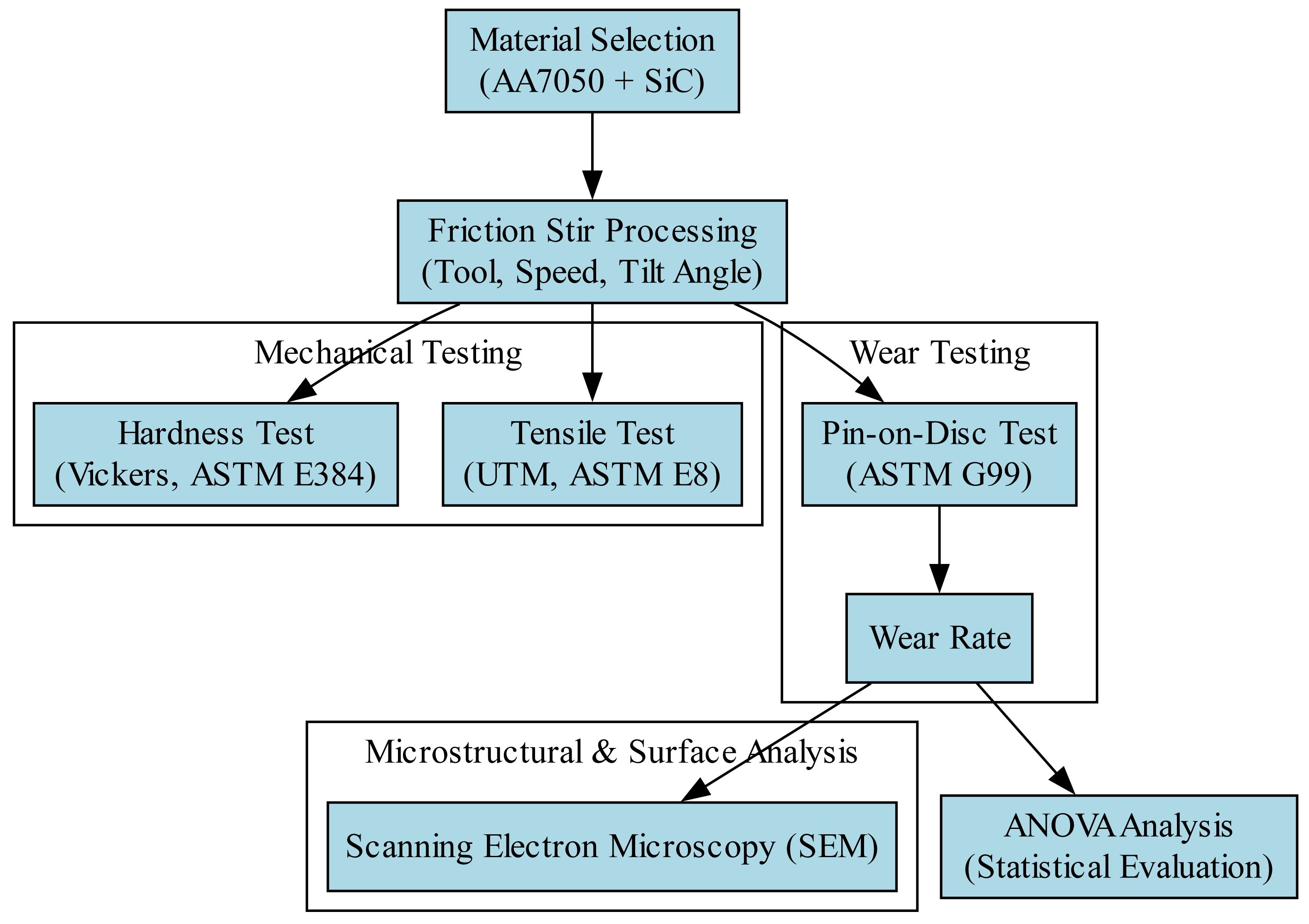
Friction Stir Processing (FSP) has emerged as an advanced solid-state processing technique to enhance the mechanical and tribological properties of aluminum matrix composites (AMCs). The wear behavior of FSP-processed AA7050-SiC composites by analyzing the influence of process parameters, SiC reinforcement, and tribological conditions. The composite specimens were fabricated using varying tool rotational speeds, traverse speeds, and tool tilt angles to achieve optimal microstructural refinement and reinforcement dispersion. Wear testing was conducted using a pin-on-disc tribometer under dry sliding conditions, and the wear rate was evaluated based on applied load, sliding speed, and distance. Microstructural characterization was performed using Scanning Electron Microscopy (SEM) to examine grain refinement, reinforcement dispersion, and wear track morphology. The results indicate that the incorporation of SiC significantly enhances hardness and wear resistance to grain boundary strengthening, load-bearing effects, and formation of a protective tribolayer. Statistical analysis using Analysis of Variance (ANOVA) was applied to determine the significance of processing parameters and their effect on wear performance. FSP conditions improve wear resistance by minimizing material loss, reducing wear debris formation, and enhancing interfacial bonding. This research provides insights into the optimization of FSP parameters for improving the tribological performance of AA7050-SiC composites, making them suitable for aerospace and structural applications.
Keywords: Friction stir process, AA7050-SIC, ANOVA
FSP is an advanced solid-state material modification technique derived from Friction Stir Welding (FSW) and has garnered significant attention for improving the mechanical and tribological properties of aluminum alloys [1]. Unlike conventional fusion-based processing techniques, FSP operates below the melting point of the material, preventing common issues such as porosity, casting defects, and segregation [2]. The severe plastic deformation induced by the rotating tool facilitates dynamic recrystallization, resulting in a refined and homogenized microstructure [3]. This unique characteristic makes FSP an effective method for grain refinement, strengthening, and enhancing wear resistance, particularly for applications in aerospace and automotive industries [4]. The mechanical properties achieved through FSP are strongly influenced by critical process parameters such as tool rotational speed, traverse speed, and the number of passes [5]. Tool rotational speed governs heat generation and material flow, while traverse speed dictates the interaction time between the tool and workpiece, affecting grain refinement and reinforcement dispersion [6]. An optimal balance between these parameters ensures uniform microstructural evolution and improved mechanical properties [7]. AA7050 aluminum alloy is widely utilized in aerospace and structural applications to its excellent strength-to-weight ratio, corrosion resistance, and fatigue performance [8]. Composed primarily of aluminum, zinc, magnesium, and copper, AA7050 exhibits high hardness and wear resistance, making it ideal for critical components in aircraft structures, defense systems, and automotive frames [9]. Conventional processing methods such as casting and fusion welding present challenges, including segregation of alloying elements, porosity, residual stresses, and coarse grains, which negatively impact the material's mechanical properties [10]. FSP has emerged as an effective solid-state processing technique to overcome these challenges [11]. By promoting dynamic recrystallization, grain refinement, and homogenization of alloying elements, FSP enhances the mechanical properties of AA7050 aluminum alloy, including hardness, strength, and wear resistance [12]. FSP facilitates the incorporation of ceramic reinforcements such as silicon carbide (SiC) into the aluminum matrix, significantly enhancing its tribological performance [13]. This ability to tailor both surface and bulk properties without altering the chemical composition has positioned FSP as a promising technique for the development of high-performance AMCs [14]. SiC has proven to be a highly effective reinforcement material for AMCs, offering superior hardness, thermal stability, and improved mechanical and tribological properties [15]. The inclusion of SiC in aluminum alloys contributes to strengthening through mechanisms such as grain refinement, Orowan strengthening, load transfer, and thermal expansion mismatch strengthening [16]. The pinning effect of SiC particles restricts grain boundary migration, leading to finer microstructures, which enhance hardness and yield strength, as described by the Hall-Petch relationship [17]. The Orowan strengthening mechanism increases resistance to plastic deformation, while the load transfer effect enhances tensile properties by distributing the applied stress between the reinforcement and the matrix [18]. Thermal expansion mismatch between SiC particles and the aluminum matrix induces residual compressive stresses, further restricting dislocation motion and improving mechanical properties [19]. The effectiveness of SiC reinforcement is highly dependent on its weight percentage. Studies indicate that an optimal SiC content, typically between 3 wt.% and 6 wt.%, provides a balance between enhanced mechanical properties and processability [20]. Lower SiC content results in insufficient strengthening, while higher content may lead to particle clustering, stress concentration, and reduced ductility [21]. Optimizing SiC content is achieving superior wear resistance, as it enhances surface hardness and minimizes material loss during sliding. FSP has also been extensively studied for its impact on wear resistance in AMCs [22]. While aluminum alloys, particularly AA7050, are known for their high strength-to-weight ratio, their wear resistance is relatively low in tribological environments. The incorporation of SiC through FSP significantly improves wear resistance by refining the microstructure and introducing strengthening mechanisms [23]. Wear behavior is influenced by adhesive wear, abrasive wear, delamination, and oxidative wear, which are governed by factors such as applied load, sliding speed, and counterface material. SiC reinforcement minimizes these wear mechanisms by enhancing surface hardness, forming a protective tribolayer, and increasing the load-bearing capacity of the composite. FSP-based aluminum composites exhibit superior wear performance compared to those fabricated through conventional methods such as stir casting and powder metallurgy. While stir casting often results in reinforcement clustering and porosity, and powder metallurgy suffers from weak interfacial bonding, FSP produces defect-free microstructures with refined grains and strong interfacial bonding, ensuring consistent wear resistance and mechanical properties. To further enhance the understanding of FSP composites, SEM is employed to analyze microstructure and worn surfaces. SEM imaging provides insights into the dispersion of SiC particles, particle clustering, and wear mechanisms such as abrasive wear, delamination, and oxidative wear [24]. In accumulation to experimental techniques, statistical tools such as ANOVA and regression models have been widely applied to optimize process parameters and predict mechanical properties. ANOVA identifies the most influential factors, such as tool rotational speed and reinforcement content, and evaluates their contribution to responses like wear rate, hardness, and tensile strength [25]. This paper intentions to evaluate the wear behavior, hardness, and tensile properties of FSP AA7050-SiC composites, employing SEM analysis and statistical tools to gain a deeper understanding of the process-property relationship.
Although significant research has been conducted on the mechanical and tribological enhancement of AMCs through FSP, several critical gaps remain. Existing studies primarily focus on single-pass FSP, while the effect of multi-pass processing on grain refinement, reinforcement distribution, and wear resistance remains underexplored. The influence of multiple passes on mechanical properties, particularly in SiC-reinforced AA7050 composites, is not well-documented. The correlation between SiC dispersion, wear track morphology, and material loss remains unclear. Most studies optimize FSP parameters based on hardness and tensile strength, but the direct influence of process variables on wear rate and coefficient of friction (CoF) has not been fully established. While ANOVA has been applied for process optimization, the use of machine learning regression models and artificial neural networks (ANNs) to predict wear rate, hardness, and tensile strength is still limited. While an optimal SiC content of 6-12 wt.% has been reported, the effect of higher SiC reinforcement levels (>12 wt.%) on mechanical performance and tribological properties has not been systematically analyzed. Addressing these gaps is crucial for optimizing FSP parameters and achieving superior wear resistance in AA7050-SiC composites, making them more suitable for aerospace and structural applications. The current work focus with the objective of
• To evaluate the effect of SiC reinforcement on the mechanical properties of AA7050 aluminum alloy, Vickers hardness and tensile strength, by analyzing the influence of different SiC weight percentages.
• To analyze the wear performance of FSP AA7050-SiC composites under varying wear conditions, including applied load, sliding speed, and sliding distance, and to assess the dominant wear mechanisms.
• To perform a detailed microstructural and worn surface analysis using SEM to investigate SiC dispersion, grain refinement, and wear track morphology, thereby identifying the primary wear mechanisms such as abrasion, delamination, and oxidative wear.
• To optimize FSP parameters (tool rotational speed, traverse speed, and tilt angle) to achieve improved wear resistance and mechanical properties of AA7050-SiC composites.
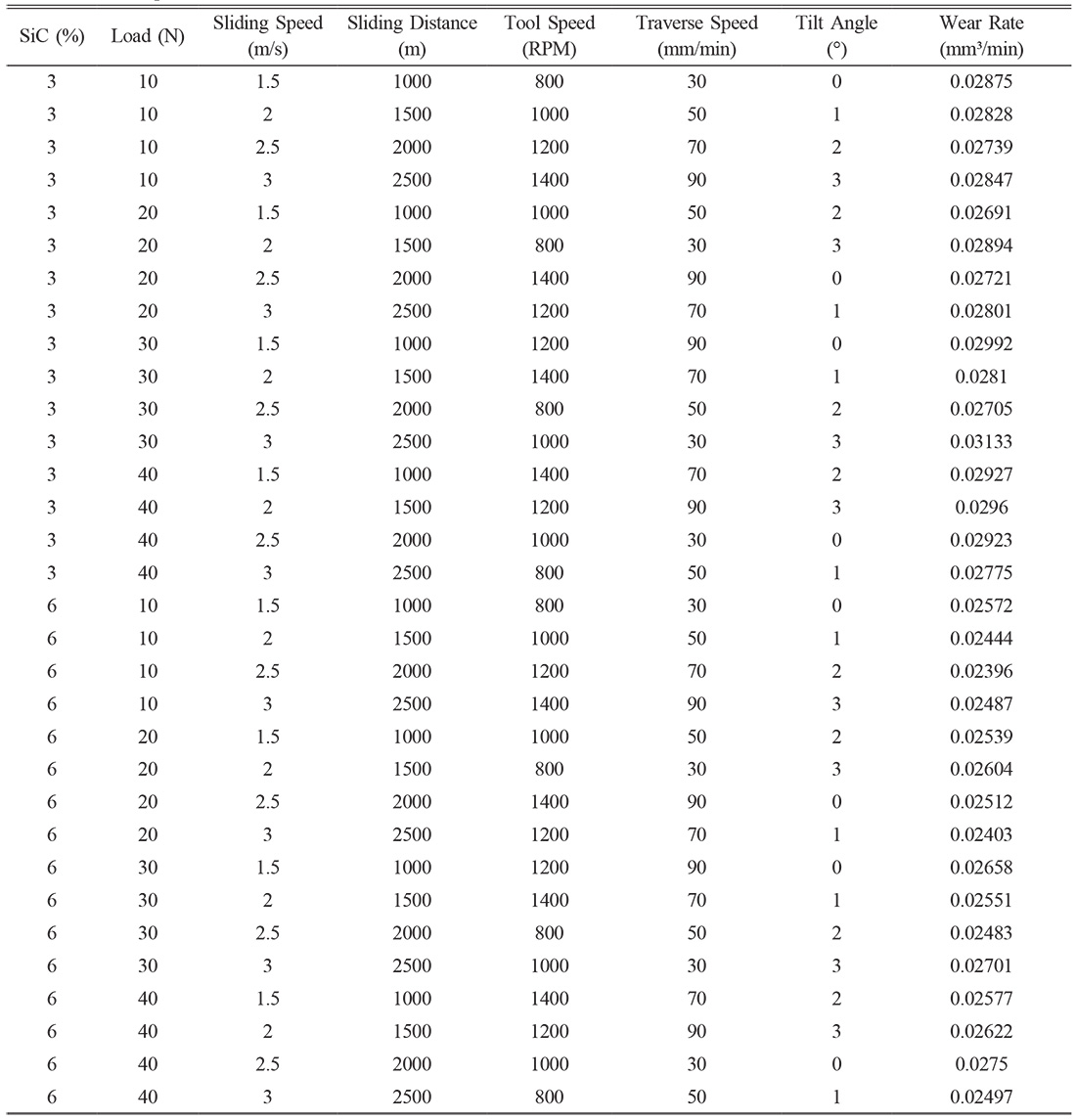
The experimental procedure involved the fabrication of FSP AA7050-SiC composites followed by mechanical and tribological characterization. The base material used in this study was AA7050 aluminum alloy, reinforced with SiC particles to enhance wear resistance. The SiC reinforcement particles were procured from Bhukhanvala Industries (India) and supplied with an average particle size of 5 µm, as specified in the manufacturer’s data sheet. FSP was performed using a CNC-controlled FSW machine with a non-consumable cylindrical tool featuring a threaded pin to ensure effective material flow and homogeneous dispersion of SiC particles within the stir zone. The reinforcing material was uniformly dispersed by loading the pre-machined surface grooves of the AA7050 plate with SiC powders and using friction stir processing. A threaded cylindrical tool and a two-pass technique were employed with orthogonal traversal between passes to diminish particle clustering and improve subsequent nugget mixing. A microhardness grid (5 × 5 indents with 0.5 mm spacing between indents) was performed over the stir zone, and the results varied within -6 HV of the average, confirming the uniform dispersion of silicon carbide particles and consistent strengthening across the treated region. After processing, the specimens were sectioned from the stir zone using WEDM to obtain test samples of uniform dimensions [26]. Tool wear has an impact on SiC dispersion by altering the efficacy of stirring, however the effect was not significant in the current study. It was mixed using a hardened threaded tool, and a two-pass orthogonal method aided mixing. There was no run-to-run variation in process parameters, hardness mapping yielded uniform results, and SEM indicated that no tool-element contamination occurred. Prior to testing, all specimens were ultrasonically cleaned and degreased to minimise oxidation processes in wear, and studies were conducted in a controlled laboratory setting to minimise exposure to moisture and oxygen. The samples were then cleaned with ethanol and dried before mechanical and tribological testing. The hardness of the processed composite was evaluated using a Vickers microhardness tester in accordance with ASTM E384. A diamond pyramidal indenter was used, and a load of 500 g was applied for a dwell time of 10 seconds. Hardness measurements were taken at multiple locations across the stir zone and base material to assess the effect of SiC reinforcement on localized strengthening. The tensile properties of the composite were determined using a UTM following ASTM E8/E8M. Dog-bone-shaped specimens were prepared with precise dimensions conforming to the standard, and the tests were conducted at a controlled strain rate. The wear behavior of the FSP AA7050-SiC composite was investigated using a pin-on-disc tribometer as per ASTM G99. Cylindrical pin specimens with a diameter of 10 mm and a length of 25 mm were prepared from the stir zone and tested against a hardened EN31 steel counter disc under dry sliding conditions. The tests were performed at varying loads in the range of 10-40 N, with Sliding Speed between 1.5 and 3 m/s, and a track diameter of 50 mm. The mass loss method was used to quantify wear, where each sample was weighed before and after testing using a high-precision electronic balance with an accuracy of ±0.1 mg. The microstructural characteristics of the processed composite and worn surfaces were analyzed using SEM. SEM imaging was employed to examine the dispersion of SiC particles within the stir zone, grain refinement in the processed region, and wear track morphology to identify wear mechanisms such as abrasion, adhesion, and delamination [27]. Statistical analysis was conducted using ANOVA to assess the significance of FSP parameters on the mechanical and tribological properties. ANOVA was performed at a confidence level of 95% (p < 0.05) to determine the influence of tool rotational speed, traverse speed, and the number of passes on wear rate, hardness, and tensile strength. This systematic experimental approach ensured a comprehensive evaluation of the mechanical, wear, and microstructural characteristics of FSP AA7050-SiC composites, providing insights into their suitability for wear-resistant applications in aerospace and automotive industries.
Wear Rate
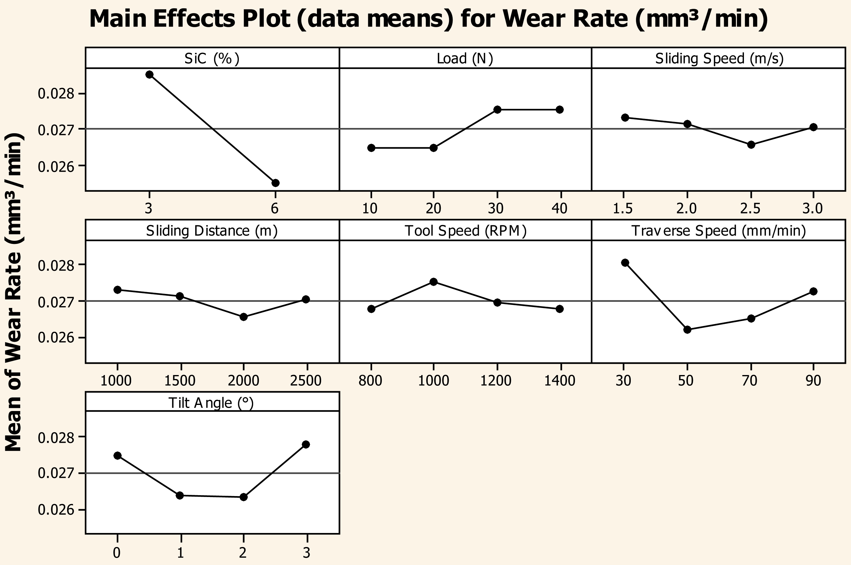
The incorporation of SiC reinforcement in the AA7050 aluminum matrix significantly affects the wear behavior of the composite. This reduction in wear rate is primarily attributed to the increase in hardness and load-bearing capacity imparted by SiC reinforcement, which strengthens the composite and minimizes material loss during wear testing. SiC, being a hard ceramic reinforcement, reducing direct metal-to-metal contact between the composite and the counterface, thereby limiting friction and material loss. The presence of SiC particles acts as a protective phase, preventing severe plastic deformation of the aluminum matrix and improving the composite's resistance to wear. Additionally, the reinforcement contributes to the formation of a load-bearing skeleton, which distributes the applied load more effectively across the material, reducing stress concentration and localized wear. The aluminum matrix undergoes less plastic deformation, leading to a lower wear rate. The wear resistance of the composite improves with an increase in SiC content, reaching its best performance at 6 wt.% SiC. At this level, the hard SiC particles effectively bear the applied load, reducing the wear of the aluminum matrix and enhancing the overall durability of the composite [28]. SiC particles act as a barrier against direct contact between the pin and the disc, mitigating friction and wear. Beyond a critical concentration, excessive SiC content can lead to agglomeration and clustering. This phenomenon results in a non-uniform stress distribution within the composite, which can induce localized brittle fracture and reduce the material's wear resistance. Although the addition of SiC reinforcement significantly enhances wear resistance, it is essential to optimize the SiC content to prevent the adverse effects of excessive reinforcement. An optimal SiC concentration ensures uniform load distribution and effective wear resistance without compromising the structural integrity of the composite.
As the applied load increases, the contact pressure between the composite surface and the counterface also rises, leading to more intense interaction at the interface. This elevated pressure enhances material removal, causing an increase in wear rate. At lower loads, the matrix material effectively supports the SiC reinforcement particles, maintaining a stable and controlled wear mechanism. At higher loads, stress concentration around the reinforcement particles increases, which may lead to their dislodgement from the matrix. Once the SiC particles are removed, the exposed aluminum matrix becomes more vulnerable to wear, resulting in an increase in material loss. The detached SiC particles contribute to a three-body abrasive wear mechanism, further intensifying material removal. Another contributing factor is thermal softening, which becomes more pronounced at higher loads. Increased frictional forces generate heat, leading to a reduction in the hardness of the aluminum matrix. This thermal softening effect enhances plastic deformation, accelerating the wear process. While the applied load of 20 N was kept constant in certain conditions, general tribological principles suggest that higher loads lead to increased friction and wear due to these combined effects.
The slight reduction in wear rate at moderate sliding speeds can be attributed to the formation of a protective tribo-layer. This layer, composed of compacted wear debris and oxidized material, acts as a barrier between the contact surfaces, reducing direct metal-to-metal contact and thereby decreasing wear. At higher sliding speeds, excessive frictional heat generation influencing wear behavior. The increased temperature leads to the softening of the aluminum matrix, reducing its hardness and making it more susceptible to plastic deformation. This softening effect results in increased material removal, contributing to a higher wear rate. The combination of high temperature and high stress leads to adhesive wear between the pin and disc. In this mechanism, localized welding occurs at asperity contacts due to the elevated temperature, and as these welded junctions break, material transfer takes place, further increasing wear [29]. At very high sliding speeds, oxidation wear becomes a contributing factor. The continuous rubbing action promotes the formation of an oxide layer on the material surface, which can act as a protective layer. Under extreme conditions, this oxide layer may become brittle and detach in the form of flakes, exposing fresh material to further wear. Despite these influencing factors, the overall effect of sliding speed on wear rate remains minimal, contributing only 0.12% to the observed variations.
The wear rate is relatively high to the removal of surface asperities. As sliding begins, microscopic irregularities on the composite surface interact with the counterface, leading to abrasive wear and increased material removal. As the sliding distance increases, a stable wear regime develops, characterized by the formation of a protective tribo-layer. This tribo-layer, composed of oxidized debris and compacted wear particles, acts as a barrier between the sliding surfaces, reducing direct contact and consequently lowering the wear rate. This stabilization is evident in the wear rate reduction observed up to 2000 m. At longer sliding distances, reinforcement depletion and matrix degradation influence wear behavior. SiC particles, which play a critical role in wear resistance, gradually detach from the surface due to continuous sliding, leading to increased matrix exposure. This depletion weakens the composite’s ability to withstand abrasion, causing wear rate to increase slightly at 2500 m. Excessive sliding distances may induce fatigue wear, where repeated cyclic loading results in microcracks within the matrix. Over time, these microcracks propagate, leading to material detachment and increased wear. The effect of sliding distance is a significant factor in determining wear performance, contributing approximately 45.64% to the overall wear rate. While moderate sliding distances promote tribo-layer formation and wear stabilization, prolonged sliding can lead to detrimental effects such as reinforcement depletion and fatigue-induced material loss.
At lower rotational speeds, the heat generated is insufficient to facilitate proper plasticization of the matrix, leading to weak bonding between the aluminum alloy and SiC reinforcement. This weak interfacial adhesion makes the composite more prone to wear, increasing the wear rate. As the rotational speed increases, enhanced stirring action promotes better distribution of the reinforcement particles within the matrix. This uniform dispersion strengthens the composite by improving load-bearing capability and reducing localized stress concentrations, which contributes to a lower wear rate. The decrease in wear rate observed at 1200 RPM indicates an optimal balance between material mixing and grain refinement, resulting in superior wear resistance. At excessively high rotational speeds, excessive heat input leads to grain growth, reducing the hardness of the material [30]. This softening effect diminishes the wear resistance, as seen in the slightly increased wear rate at 1000 RPM. Beyond this point, the wear rate stabilizes at 1400 RPM, the combined effects of enhanced reinforcement distribution and grain coarsening reach an equilibrium. While better material mixing continues to improve the wear resistance, the simultaneous reduction in hardness due to grain growth counteracts this effect, leading to a nearly constant wear rate. The tool rotational speed in determining the wear behavior of FSP composites. An optimized speed ensures adequate heat generation, uniform reinforcement distribution, and fine grain structure, thereby enhancing wear resistance.
At a lower traverse speed of 30 mm/min, can be attributed to prolonged heat exposure and excessive material softening, leading to grain coarsening and inadequate dispersion of SiC particles. Wear in the AA7050 SiC composites was mostly load-dependent, sliding speed played a minor role in comparison to load and sliding distance. The loads rose in direct proportion to the area of contact and contact tension at the interface, resulting in a faster removal of material. Similarly, the sliding distance determined the overall sliding work as well as the amount of debris generated. In contrast, at the studied range (1.5-3.0 m/s), the variation in sliding speed had very minor effects on the flash temperature. Lower traverse speeds result in excessive plastic deformation, which can lead to particle clustering and insufficient mechanical interlocking between the reinforcement and the matrix. As a result, the composite becomes more susceptible to material removal during wear testing. When the traverse speed was increased to 50 mm/min, the improvement can be linked to better distribution of SiC particles within the matrix and the formation of a more refined grain structure due to dynamic recrystallization. At this speed, the tool effectively stirs the material, ensuring uniform reinforcement dispersion and enhancing the composite's wear resistance. As the traverse speed increased further to 70 mm/min, the slight increase suggests that higher speeds may begin to compromise proper mixing, leading to defects such as voids or regions with non-uniform reinforcement dispersion, reducing the effectiveness of wear resistance enhancement [31]. At the highest traverse speed of 90 mm/min, the rise in wear rate is insufficient heat input and improper material mixing, which can cause defects such as porosity and a lack of uniform reinforcement distribution. Higher traverse speeds reduce the duration of tool-material interaction, limiting the diffusion of SiC particles within the matrix and leading to inconsistencies in hardness and wear resistance. The presence of these microstructural defects can result in increased material loss during wear testing.
A moderate tool tilt angle facilitates proper material stirring and redistribution, which enhances grain refinement and ensures uniform dispersion of SiC particles within the aluminum matrix. This refinement improves hardness and wear resistance, leading to a reduction in the wear rate at tilt angles of 1° and 2°. The lowest wear rate observed at 1° and 2° suggests an optimal balance between material mixing and mechanical interlocking, promoting superior tribological performance. At a tilt angle of 0°, insufficient plastic deformation and inadequate material mixing occur, leading to poor bonding between the matrix and reinforcement particles. This weak interface results in higher wear due to localized detachment of material during sliding contact. At a tilt angle of 3°, excessive material flow and turbulence introduce defects such as voids and improper bonding, thereby increasing the wear rate. The rise in wear rate at higher tilt angles suggests that beyond an optimal threshold, excessive stirring negatively impacts the microstructural integrity of the composite, leading to higher material loss. FSP enables in-situ grain refining, curing of defect, and uniform particle distribution without the need for high-temperature consolidation, hence avoiding the porosity and segregation issues associated with traditional techniques. At the industrial scale, this translates into increased wear resistance, mechanical dependability, and reduced post-processing, making FSP more energy efficient. Adding 6 wt.% SiC resulted in a wear rate that was about 37 percent lower than that of the unreinforced alloy at 20 N loading and a sliding speed of 2.5 m/s. Similar investigations using FSP-fabricated AA6061 -SiC composites have shown a 20% reduction in wear rate under the same condition [32], whilst AA7075 -Al2O3 systems have shown 18.25% improvements [33]. C omposite cast AA6063-SiC demonstrated lower resilience, with wear rate decreasing by less than 10% at larger reinforcing fractions [34].
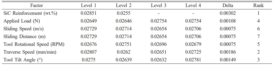
The ANOVA Table 2 for means provides insights into the relative effect of these parameters on the wear behavior of the material. Among all the parameters, SiC reinforcement exhibited the highest delta value (0.00302), making it the most influential factor in determining the wear rate. The SiC particles significantly reduced wear to their superior hardness and ability to withstand high contact stresses. This reduction in wear rate can be attributed to the reinforcement particles acting as a barrier between the contacting surfaces, thereby minimizing direct metal-to-metal contact. The presence of SiC also promotes load-bearing capacity, reducing localized plastic deformation and improving overall wear resistance. Applied load (N) ranked as the fourth most influential factor with a delta value of 0.00108. While higher loads generally lead to increased wear due to higher contact pressure and material removal, the presence of SiC reinforcement helps in mitigating severe wear by distributing the applied stress more effectively. Beyond a critical load, reinforcement particles may get dislodged, resulting in increased abrasive wear. Sliding speed (m/s), sliding distance (m), and tool rotational speed (RPM) exhibited relatively low delta values (0.00075 each), indicating that their effect on wear rate is comparatively minor. This suggests that within the tested range, variations in these parameters did not significantly alter the wear response. The minor effect of sliding speed may be attributed to the formation of a stable oxide layer at moderate speeds, which reduces wear [35]. At extremely high speeds, thermal softening of the matrix could accelerate wear, a factor that may not have been prominent within the investigated conditions. Sliding distance showed a similar trend, where initial asperity removal might have contributed to higher wear, but subsequent stabilization of the tribolayer reduced material loss over longer distances. Traverse speed (mm/min) and tool tilt angle (°) ranked as the second and third most significant factors, with delta values of 0.00186 and 0.00149. Higher traverse speeds can influence material flow and reinforcement distribution, impacting the wear behavior. Improper mixing due to an excessively high traverse speed can lead to clustering or uneven distribution of reinforcement particles, increasing the wear rate in localized regions. An optimal traverse speed ensures homogeneous dispersion of reinforcements, improving wear resistance. The effect of tool tilt angle on wear behavior is attributed to its role in controlling the material flow and consolidation during processing. A well-optimized tilt angle facilitates better bonding between the reinforcement and the matrix, enhancing wear performance. An excessive tilt angle can lead to defects such as voids and improper material mixing, contributing to increased wear. The ranking of parameters based on their delta values provides a clear indication that SiC reinforcement the most dominant role in controlling wear rate, followed by traverse speed and tool tilt angle. The critical importance of reinforcement incorporation and proper processing conditions in optimizing wear resistance. The relatively lower influence of sliding speed, sliding distance, and tool rotational speed suggests that within the tested range, these parameters do not significantly alter the material wear response. The ANOVA revealed that rotational speed, traverse speed, and tilt angle were the most important FSP parameters influencing wear behaviour (p < 0.05). The sliding distance and load had the greatest effect sizes, accounting for roughly 47.8% and 27.3% of the variation, respectively, while tool speed accounted for around 18.7%. These effect sizes showed that, in practice, adjusting the sliding distance and load has the greatest impact on wear resistance.
Microstructure
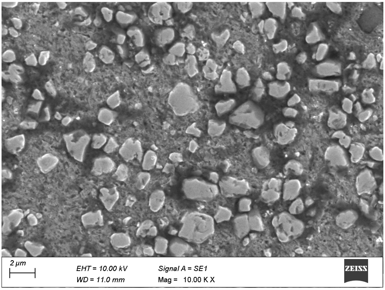
The microstructural examination of the FSP AA7050
-SiC composite, as observed in the Fig. 3, reveals significant modifications in grain morphology, reinforcement dispersion, and defect characteristics. The dynamic recrystallization induced by FSP has resulted in a refined and homogenized microstructure, significantly improving the composite’s mechanical and tribological properties. The grain structure exhibits a substantial reduction in grain size due to the severe plastic deformation and thermal cycling associated with FSP. The presence of fine, equiaxed grains in the stir zone, compared to the coarse grains of the base material, is indicative of effective dynamic recrystallization. The grain refinement follows the Hall-Petch relationship, where reduced grain size contributes to enhanced hardness and strength. The formation of high-angle grain boundaries (HAGBs) to the intense shear deformation further strengthens the material, improving its wear resistance and mechanical properties. The dispersion of SiC particles within the aluminum matrix determining the composite’s mechanical performance. The microstructure exhibits homogeneous distribution of SiC reinforcements, with minimal agglomeration, ensuring uniform load transfer and strengthening mechanisms. Porosity and void formation were low in the treated AA7050-SiC composites. It was evaluated by SEM examination, and analysis verified that porosity levels were less than 1% by area fraction, with no major voids and tunnel flaws found. The homogeneous hardness profile across the nugget corroborated the lack of considerable porosity.
Localized clustering of SiC particles is observed in some regions, which may contribute to stress concentration and reduce the overall ductility. The degree of interfacial bonding between the SiC particles and the matrix is critical in enhancing the composite’s wear resistance, as strong bonding minimizes the risk of particle pull-out during tribological loading. Porosity and defect analysis indicates the presence of minimal voids or microcracks in the processed region, demonstrating the effectiveness of FSP in producing a defect-free microstructure compared to conventional fabrication techniques such as stir casting [36]. The absence of significant unbonded reinforcement particles confirms the strong metallurgical bonding achieved through FSP, which contributes to improved mechanical integrity. The formation of subgrains and dislocation structures within the stir zone is evident, suggesting that the high strain and temperature cycles during FSP promote dynamic recovery and recrystallization. This phenomenon enhances the mechanical properties by refining the microstructure while maintaining sufficient ductility. The precipitate distribution analysis reveals a uniform dispersion of strengthening phases such as MgZn₂, which enhances hardness and wear resistance. The dissolution and redistribution of precipitates contribute to improved mechanical properties by restricting dislocation motion and increasing strength.
Hardness and Tensile Strength
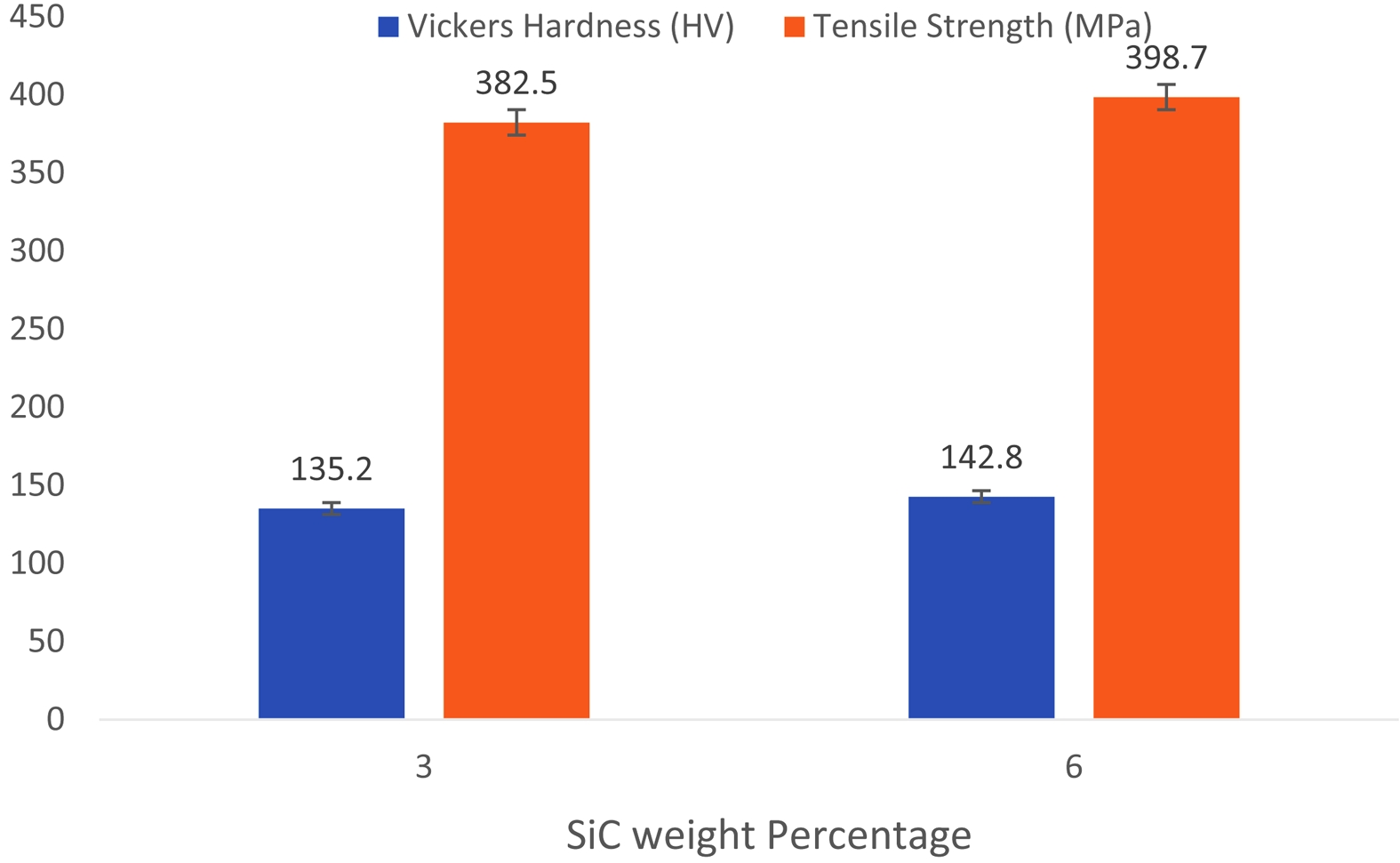
Fig. 4 presents the variation in HV and Tensile Strength (MPa) of the FSP AA7050-SiC composite as a function of SiC reinforcement content (3 wt.% and 6 wt.%), following the standardized testing procedures [37]. The Vickers HV testing was conducted in accordance
with ASTM E384, using a load of 500 g and a dwell time of 15 seconds. The increase in hardness from 135.2 HV at 3 wt.% SiC to 142.8 HV at 6 wt.% SiC is attributed to grain refinement, dispersion strengthening, and thermal mismatch-induced residual stresses. The grain refinement mechanism follows the Hall-Petch relationship, where the reduction in grain size increases hardness by restricting dislocation motion. The Orowan strengthening mechanism contributes to hardness enhancement as the dispersed SiC particles act as obstacles to dislocation movement. The coefficient of thermal expansion (CTE) mismatch between the SiC reinforcement and the aluminum matrix generates compressive residual stresses, further hindering plastic deformation and improving indentation resistance.
The tensile testing was performed as per ASTM E8, using a UTM with a constant crosshead speed of 2 mm/min. The tensile strength of the composite increased from 382.5 MPa at 3 wt.% SiC to 398.7 MPa at 6 wt.% SiC, demonstrating the reinforcing effect of SiC particles. The improvement in tensile properties is primarily attributed to the load transfer mechanism, where the hard SiC particles bear part of the applied load, reducing stress concentration on the softer AA7050 matrix. The Orowan strengthening mechanism further enhances strength by forcing dislocations to bow between the fine SiC particles, increasing resistance to plastic deformation. The Hall-Petch effect strengthening by reducing the slip length of dislocations to finer grain structures. Proper interfacial bonding between the reinforcement and matrix, facilitated by severe plastic deformation during FSP, ensures effective stress transfer, leading to improved mechanical performance. Excessive reinforcement content beyond an optimal level may lead to clustering, increasing stress concentration sites and reducing ductility. SiC reinforcement significantly enhances the hardness and tensile strength of the FSP AA7050 composite, making it suitable for high-performance applications requiring superior mechanical properties.
SEM Analysis
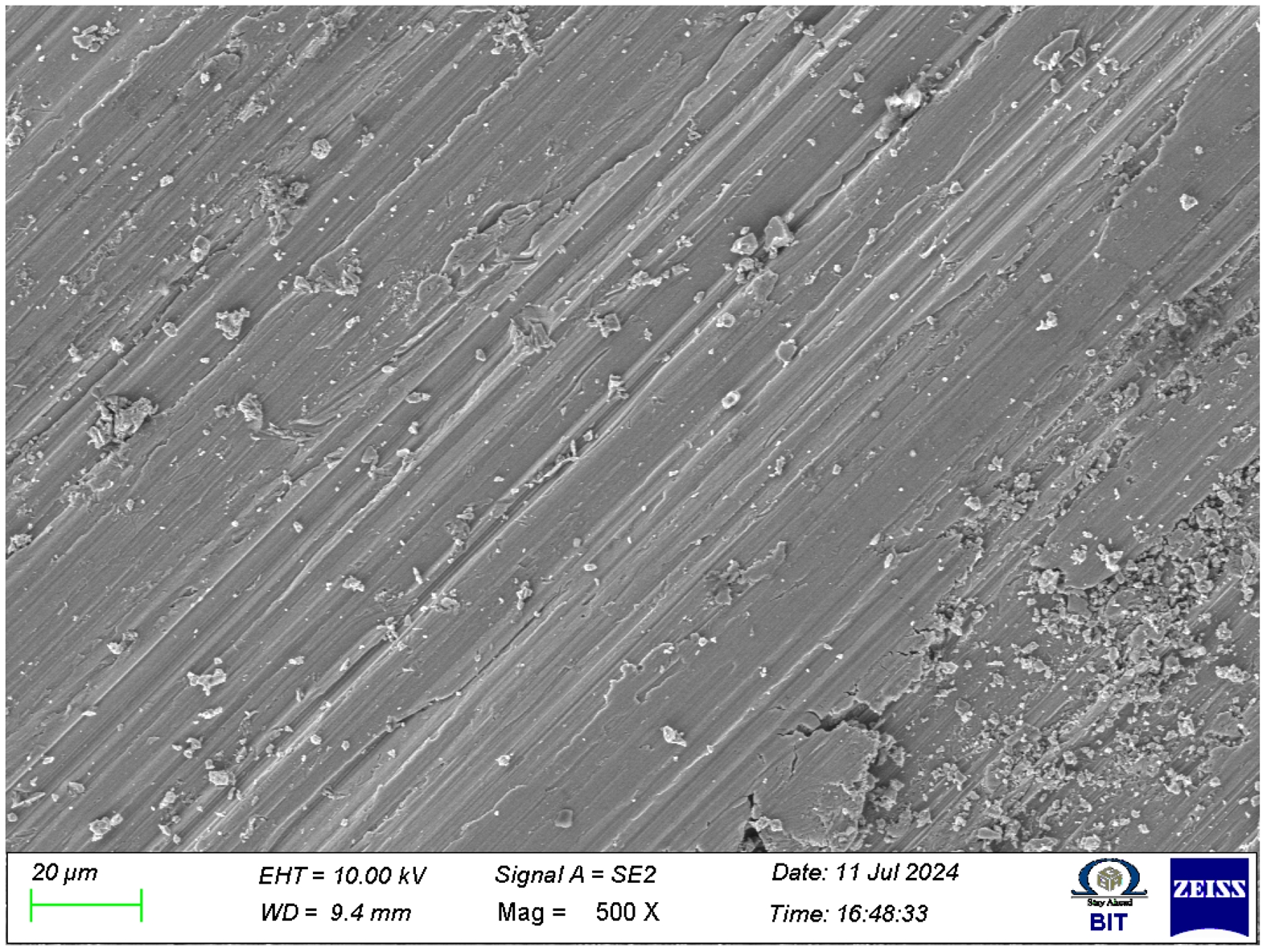
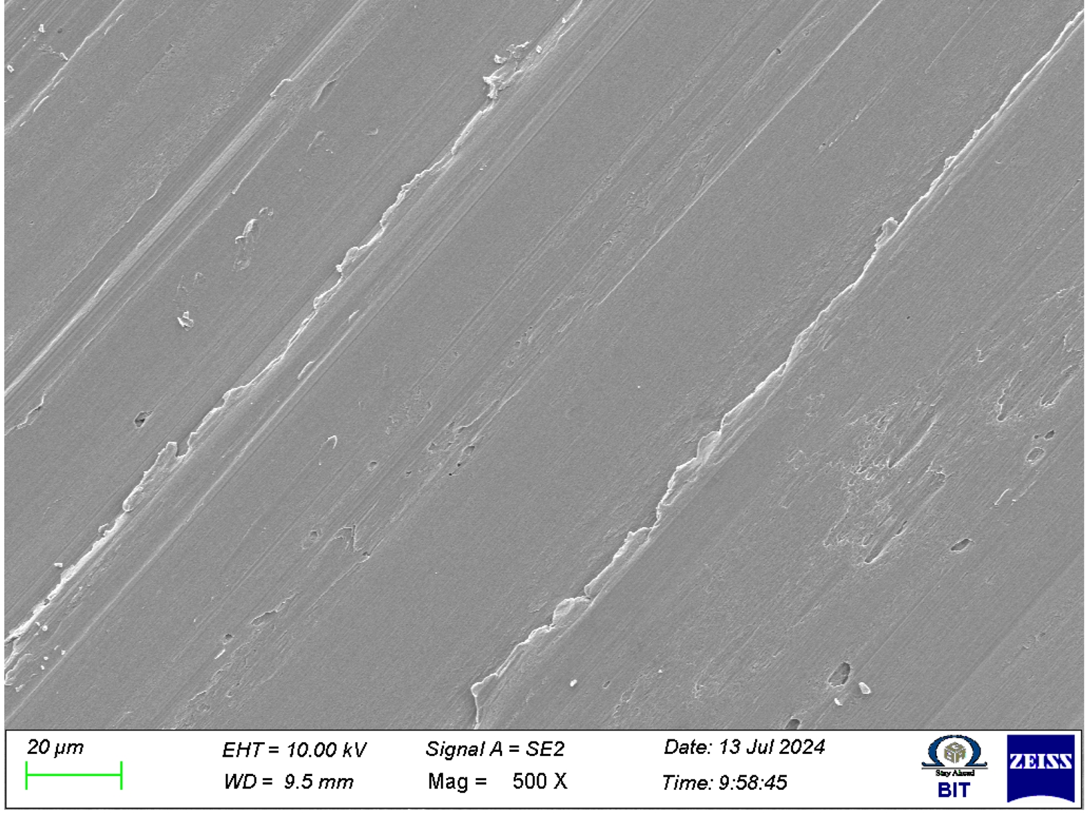
The SEM analysis of the worn surface of FSP AA7050-SiC composite, as in Fig. 5, provides significant insights into the reinforcement particle morphology, size distribution, and deformation characteristics induced by wear. The micrograph reveals a combination of mechanically induced grooves, fragmented reinforcement particles, and surface debris, which are key indicators of the underlying wear mechanisms. The morphological evolution of SiC particles is evident in the micrograph, where some particles appear rounded, while others retain their angular characteristics. This transformation is primarily attributed to the intense thermo-mechanical interaction during the FSP and subsequent wear testing. The thermal softening of the aluminum matrix and mechanical shearing forces facilitate rounding of initially sharp-edged SiC particles, reducing stress concentrations and enhancing wear resistance. Agglomerated and oversized SiC clusters are also observed, which can act as stress concentrators, leading to localized material detachment. The size distribution of SiC particles defining the wear performance of the composite. The presence of finely fragmented SiC particles dispersed within the worn surface suggests effective load transfer and reinforcement retention. These particles function as load-bearing elements, restricting severe matrix deformation and contributing to improved wear resistance. Regions exhibiting larger SiC clusters indicate incomplete particle dispersion during FSP, which can result in microcrack initiation and material delamination [38]. The degree of fragmentation observed in Fig. 5 implies that the applied wear conditions led to particle attrition, where larger particles fractured into smaller fragments, further embedding into the matrix and influencing tribological performance. The aspect ratio variation of SiC particles post-FSP is another key observation from the micrograph. The elongated wear grooves indicate the directionality of the abrasive wear mechanism, where SiC particles act as micro-cutting tools, generating parallel striations on the matrix surface. The deformation of these particles suggests a progressive reduction in aspect ratio, transitioning from elongated and angular structures to more equiaxed geometries due to sustained sliding interactions. This transformation enhances the composite’s load-bearing capacity by minimizing stress concentrations at particle-matrix interfaces. The presence of debris accumulation on the worn surface suggests a synergistic effect of abrasive and adhesive wear mechanisms. The fragmented SiC particles and matrix debris indicate that material removal occurs through a combination of micro-cutting and adhesion, where detached particles contribute to third-body abrasion. The distribution of debris is non-uniform, with higher concentrations along the wear grooves, indicating regions of localized stress and strain accumulation.
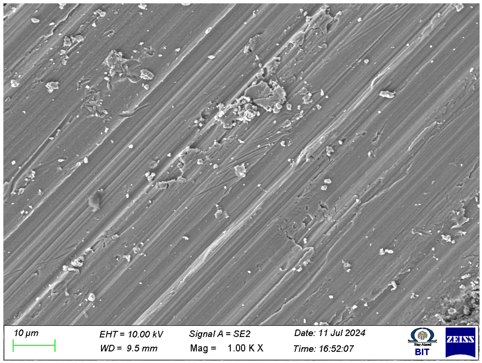
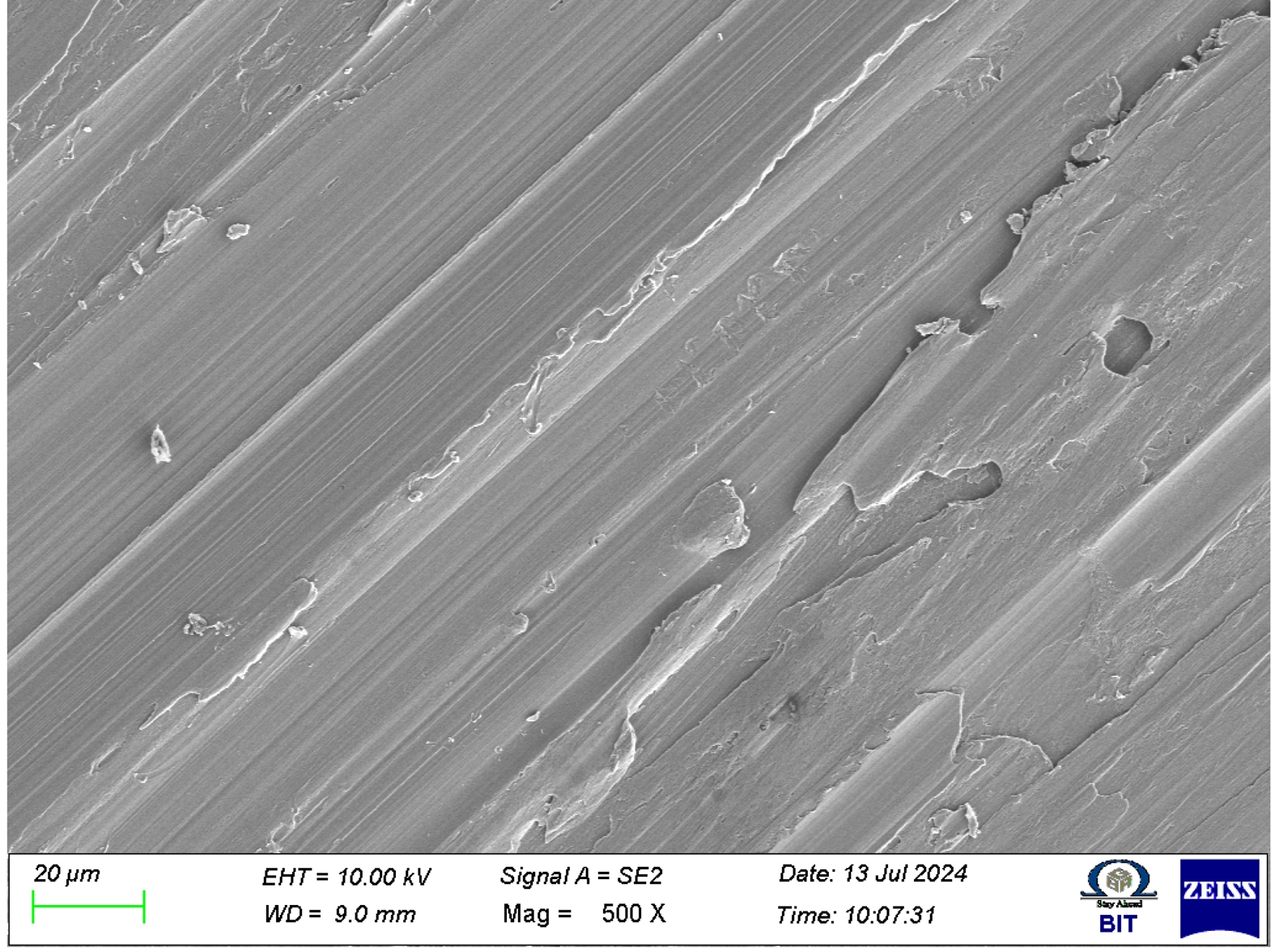
The interfacial bonding between SiC reinforcement and the AA7050 aluminum matrix determining the mechanical integrity and tribological performance of the composite. The SEM micrograph (Fig. 6) into the nature of SiC-Al bonding, highlighting the extent of adhesion and potential defects at the interface. A well-bonded interface ensures effective load transfer from the matrix to the reinforcement, contributing to enhanced wear resistance and mechanical strength. Weak interfacial bonding may result in particle debonding, leading to premature material failure. The SEM analysis reveals a combination of well-adhered SiC particles and regions where interfacial debonding has occurred [39]. Some areas exhibit strong matrix-reinforcement bonding, suggesting efficient diffusion and mechanical interlocking during FSP. Voids and gaps at certain SiC-Al interfaces indicate inadequate bonding, which could serve as potential initiation sites for crack propagation during mechanical loading. The presence of these gaps suggests insufficient metallurgical bonding, likely influenced by the thermal and mechanical conditions during FSP. The analysis identifies SiC particle pull-out, a significant wear-related phenomenon that can affect the composite's surface integrity. The occurrence of pull-out is evident in void-like features scattered across the worn surface, indicating detachment of SiC particles from the matrix to insufficient adhesion. These detached particles can contribute to third-body abrasion, further intensifying wear. The extent of particle pull-out suggests that optimizing FSP parameters, such as rotational speed and traverse speed, is essential to achieve improved interfacial bonding and minimize wear-related degradation. The SEM micrograph reveals micro-cracks propagating from the debonded interfaces, highlighting the role of interfacial defects in accelerating wear damage. These micro-cracks can lead to severe delamination, reducing the material's load-bearing capacity. The observed features suggest that strategies such as optimizing process parameters and post-processing heat treatments could enhance interfacial bonding and reduce wear-induced particle detachment.
The microstructural evolution of the FSP-processed AA7050-SiC composite is significantly influenced by
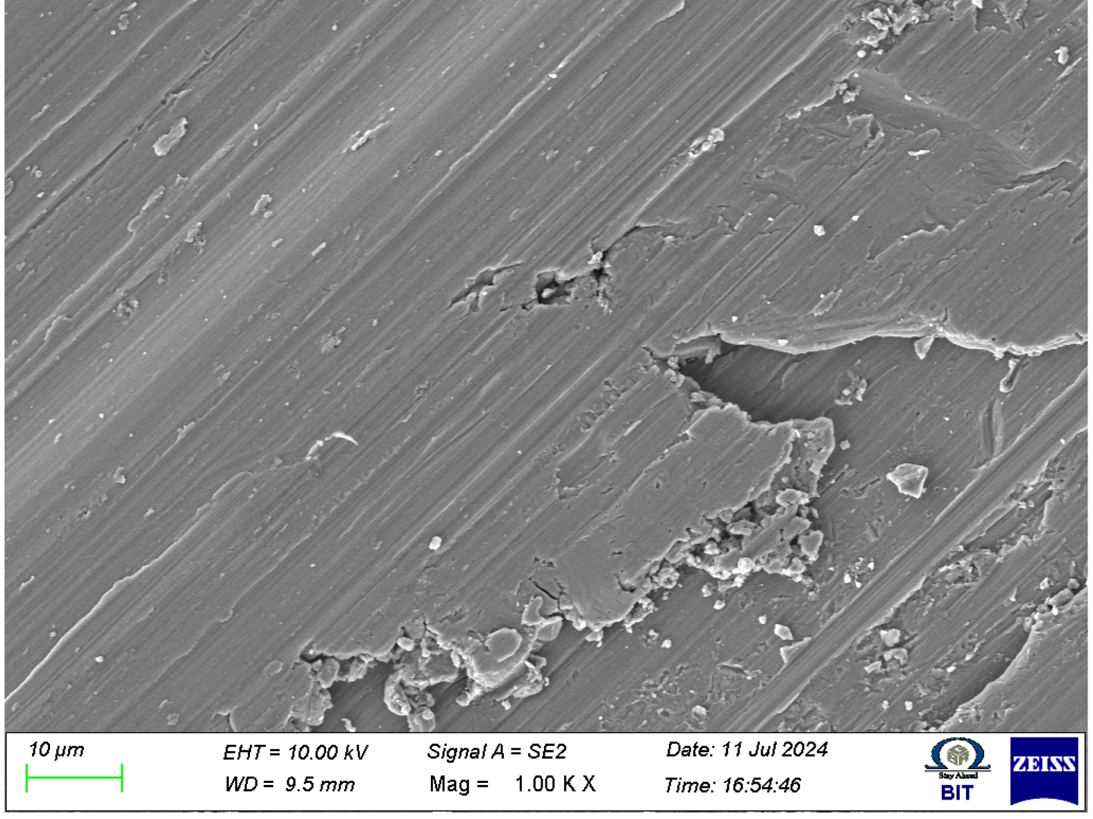
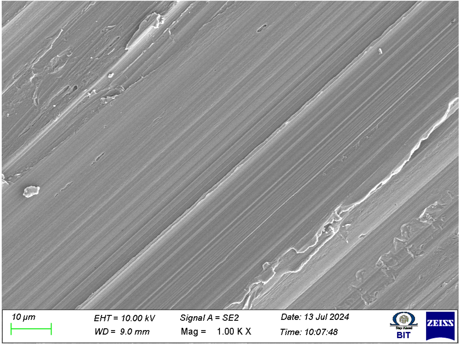
dynamic recrystallization (DRX), which leads to substantial grain refinement within the stir zone. The SEM micrograph (Fig. 7) reveals distinct grain structures, the effects of severe plastic deformation and thermal exposure during the FSP process. The interaction between SiC reinforcements and the aluminum matrix grain refinement by acting as nucleation sites for recrystallization. The presence of ultrafine grains in the stir zone suggests effective DRX, which contributes to improved mechanical properties such as hardness and wear resistance. The formation of subgrain structures is evident in the micrograph, highlighting the accumulation of plastic strain within the matrix. These subgrains indicate progressive dislocation rearrangement and recovery processes occurring due to the thermomechanical conditions imposed by FSP. The presence of these subgrain boundaries enhances the strength of the composite by impeding dislocation motion, thereby improving its hardness and mechanical stability [40]. The densification of grain boundaries around the SiC particles further confirms the role of reinforcement in influencing the recrystallization process, as the particles serve as barriers to grain growth, refining the overall microstructure. The micrograph captures highly misoriented grains near the SiC reinforcements, indicative of strain localization and deformation heterogeneity. The presence of dislocation structures at the grain boundaries suggests that localized stress concentrations around the SiC particles contribute to strain hardening. These deformation mechanisms determining the composite’s mechanical performance, particularly in enhancing its wear resistance. The distribution of dislocations and their interaction with the grain boundaries dictate the material's ability to withstand applied loads without premature failure.
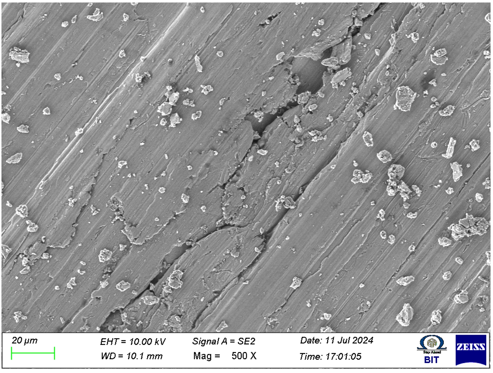
The SEM (Fig. 8) reveals the presence of microvoids and defects, which significantly influence the mechanical integrity of the material. Porosity formation within the stir zone is evident, primarily attributed to incomplete material flow during the friction stir process. These voids may originate from insufficient plasticization of the aluminum matrix, entrapped gases, or improper diffusion bonding at the reinforcement-matrix interface. The presence of microporosity can act as stress concentration sites, adversely affecting the composite’s mechanical strength and fatigue resistance. Crack propagation paths observed in the micrograph provide critical insights into the failure mechanisms of the composite. The cracks predominantly appear along grain boundaries and at reinforcement-matrix interfaces, indicating localized stress accumulation. The orientation of these cracks suggests that they may initiate due to cyclic loading or strain incompatibility between the aluminum matrix and SiC particles. Such defects can significantly reduce the load-bearing capacity of the composite, making it more susceptible to early failure under mechanical stresses. Enhancing the FSP parameters, such as increasing tool rotation speed or optimizing traverse speed, could improve material flow and reduce defect formation. Another significant observation is the presence of unbonded SiC particles within the matrix. These particles, which appear loosely embedded or completely detached, indicate insufficient interfacial bonding. Poor bonding between the SiC reinforcement and the aluminum matrix reduces the effectiveness of load transfer, leading to premature material failure under mechanical loading. The weak interfacial adhesion is often a result of improper mixing during FSP or the presence of oxide layers on the reinforcement surfaces. The presence of these defects highlights the importance of process optimization in achieving a defect-free microstructure. While FSP offers a significant advantage in producing refined grains and improved mechanical properties, the formation of microvoids, cracks, and unbonded reinforcement particles can limit the composite’s structural integrity.
The SEM (Fig. 9) presence of deep grooves and cutting marks on the wear track confirms the occurrence of abrasive wear, which is primarily induced by hard SiC reinforcement particles. These features indicate the presence of both two-body and three-body abrasive wear mechanisms. Two-body wear occurs when hard SiC particles embedded in the matrix plow through the surface, while three-body wear results from loose particles acting as abrasives between the contacting surfaces. The severity of this mechanism is influenced by the applied load and sliding conditions, which determine the extent of material removal. Delamination and layered surface formation are also evident in the worn morphology, suggesting a fatigue-induced wear mechanism. The cyclic loading during the wear process leads to the progressive detachment of thin layers from the surface, forming characteristic delamination scars. This process is attributed to subsurface crack initiation and propagation, which eventually results in material removal in the form of wear debris [41]. The presence of delaminated regions indicates that the material undergoes repeated plastic deformation, reducing its load-bearing capacity and accelerating wear rate. The plastic flow of the aluminum matrix is another significant observation in the wear track. Under severe wear conditions, the aluminum-rich regions undergo localized plastic deformation, leading to smearing and material flow along the sliding direction. This phenomenon is a result of thermal softening due to frictional heating, which reduces the hardness of the aluminum matrix and makes it more susceptible to plastic deformation. The extent of plastic flow depends on the applied normal load and frictional heat generated during sliding, affecting the overall wear behavior. The presence of a tribolayer, also referred to as a mechanically mixed layer (MML), is observed on the worn surface. This oxide-rich layer forms due to the combined effects of oxidation and mechanical mixing of wear debris with the matrix. The development of this protective tribolayer plays a crucial role in influencing the wear resistance of the composite. A well-adhered MML can reduce direct metal-to-metal contact, minimizing wear, whereas a weak or discontinuous MML may result in its removal, exposing the material to further degradation. The formation and stability of this tribolayer are dependent on factors such as sliding speed, normal load, and ambient conditions.
The SEM (Fig. 10) reveals critical insights into the size, morphology, and accumulation of wear debris, which significantly influence the overall tribological behavior of the composite. The presence of wear debris in varying sizes, ranging from fine particles to larger fragments, different wear mechanisms. Fine debris is typically associated with mild abrasive wear and self-lubricating effects, reducing direct metal-to-metal contact and thereby minimizing the wear rate. Coarse wear debris, often observed in severe wear conditions, increases third-body interactions, leading to enhanced material removal and surface degradation. The nature of wear debris accumulation on the worn surface provides further indications of self-lubricating behavior. A significant build-up of wear debris may contribute to the formation of a protective layer that prevents direct contact between the mating surfaces, thereby reducing wear. Excessive debris accumulation can also lead to increased third-body abrasion, which accelerates surface damage. The balance between these opposing effects is crucial in determining the wear performance of the composite under different operating conditions. The presence of flake-like debris suggests oxidative wear, particularly under high-temperature sliding conditions. This is attributed to the formation and subsequent detachment of oxide layers due to repeated frictional heating and mechanical stresses. The oxidation of the aluminum matrix during sliding results in the formation of a brittle oxide layer, which eventually fractures and generates wear debris in the form of flakes. The extent of oxidative wear is influenced by factors such as sliding velocity, contact pressure, and environmental conditions. SEM analysis reveals surface fractures and fatigue-induced crack formation, which are indicative of cyclic loading effects during the wear process [42]. Microcrack initiation is commonly observed at the SiC-matrix interfaces or along grain boundaries, where stress concentrations are high. These microcracks serve as nucleation sites for crack propagation, eventually leading to material detachment in the form of wear debris. The presence of fatigue striations on the worn surface confirms the occurrence of fatigue wear, where repeated stress cycles progressively weaken the material until failure occurs. The width and spacing of these striations provide insights into the severity of cyclic loading and its impact on wear performance. The fracture patterns observed in the worn regions further differentiate between brittle and ductile failure modes. Brittle fracture is characterized by sharp, jagged edges, which indicate sudden material failure under high-stress conditions. On the other hand, ductile fracture features dimples and tear ridges, signifying plastic deformation before failure. The transition between these fracture modes depends on the applied load, material properties, and wear conditions. Understanding these failure mechanisms is essential for optimizing processing parameters to enhance wear resistance and durability.
The SEM analysis of the worn surface of the FSP-processed AA7050-SiC composite (Fig. 11) reveals distinct microstructural modifications due to severe plastic deformation and material displacement effects. The presence of localized shear bands suggests intense plastic strain accumulation during the wear process, which significantly influences the wear behavior. These shear bands, formed due to the high-stress sliding contact, alter the microstructure by inducing strain hardening and creating high-angle grain boundaries (HAGBs). The increased density of dislocation structures in these regions is indicative of strain-induced boundary formation, determining the wear resistance of the composite. The SEM extensive ploughing marks, which are characteristic features of abrasive wear. The depth and width of these ploughing grooves are influenced by the presence of hard SiC particles acting as micro-cutting tools. The interaction between these reinforcing particles and the opposing wear surface results in severe material displacement, leading to pronounced grooves and surface roughening. The extent of ploughing is directly correlated with the applied load and sliding conditions, as deeper grooves indicate increased material removal and higher wear rates. The possibility of metallic transfer onto the counterface is evident from material adhesion observed on the worn track. During sliding wear, aluminum from the composite matrix undergoes adhesion and subsequent transfer to the counterface, forming tribolayers that affect the frictional characteristics. This phenomenon can either reduce wear by forming a protective transfer layer or increase wear by causing adhesive wear failure, depending on the stability of the transferred material. The extent of metallic transfer is influenced by the nature of the contact interface and the prevailing wear mechanisms.
The SEM (Fig. 12) reveals significant oxidative wear characteristics and residual stress-induced surface modifications. The presence of an oxide-rich layer on the worn surface suggests oxidation-assisted wear mechanisms, where elevated temperatures during sliding contribute to the formation of a tribolayer. This oxide layer acts as a protective barrier, reducing direct metal-to-metal contact and mitigating severe wear. The thermal instability of the oxide layer leads to crack formation due to cyclic thermal stresses. These micro-cracks within the oxide film compromise its long-term stability, potentially accelerating material loss in subsequent wear cycles. Residual stress-induced surface features are also evident, characterized by stress relief patterns in regions subjected to cyclic loading [43]. These patterns indicate localized deformation responses to high contact stresses, which influence the residual stress distribution across the worn surface. Such stress relief mechanisms play a crucial role in determining the wear resistance, as they can either enhance the material’s load-bearing capability or promote crack initiation under severe sliding conditions. The SEM analysis captures nano-scale modifications to severe wear, highlighting the evolution of ultrafine wear-induced surface features. These nanoscale wear traces indicate progressive material degradation, influencing the mechanical performance of the composite. The combination of oxidative wear and residual stress effects significantly impacts the overall wear behavior, demonstrating the interplay between thermally induced oxidation processes and mechanical stress responses during tribological interactions.
|
Fig. 1 Research Methodology of the work. |
|
Fig. 2 Main Effect Plot for Wear Rate. |
|
Fig. 3 Microstructure Showing SiC Particle Dispersion and Grain Refinement in FSP AA7050-SiC Composite. |
|
Fig. 4 Variation of Vickers Hardness and Tensile Strength of FSP AA7050-SiC Composites with SiC Reinforcement Content. |
|
Fig. 5 SEM Micrograph of Worn Surface of FSP AA7050-SiC Composite at4 500× Magnification. |
|
Fig. 6 SEM Micrograph of Worn Surface of FSP AA7050-SiC Composite Highlighting SiC-Aluminum Interfacial Bonding and Particle Pull-Out at 1000× Magnification. |
|
Fig. 7 SEM Micrograph of FSP AA7050-SiC Composite Showing Grain Refinement, Subgrain Structures, and Dislocation Accumulation at 1000× Magnification. |
|
Fig. 8 SEM Micrograph of FSP AA7050-SiC Composite Showing Microvoids, Crack Propagation Paths, and Unbonded SiC Particles at 500× Magnification. |

|
Fig. 9 SEM Micrograph of Worn Surface of FSP AA7050-SiC Composite Showing Abrasive Wear Features, Delamination, Plastic Flow, and Tribolayer Formation at 1000× Magnification. |
|
Fig. 10 SEM Micrograph of Worn Surface of FSP AA7050-SiC Composite Showing Wear Debris, Oxidative Flakes, Fatigue Striations, and Fracture Patterns at 500× Magnification. |
|
Fig. 11 SEM Micrograph of Worn Surface of FSP AA7050-SiC Composite Showing Shear Bands, High-Angle Grain Boundaries, Ploughing Grooves, and Metallic Transfer at 500× Magnification. |
|
Fig. 12 SEM Micrograph of Worn Surface of FSP AA7050-SiC Composite Showing Oxidative Wear Effects, Thermal Crack Formation in Oxide Layers, and Residual Stress-Induced Surface Modifications at 1000× Magnification. |
The incorporation of SiC as a reinforcement in the AA7050 aluminum alloy matrix via FSP has been found to significantly improve the wear resistance, hardness, and tensile strength of the composite. The optimum performance was observed at 6 wt.% SiC reinforcement, attributed to enhanced load-bearing capacity, grain refinement, and effective dispersion strengthening mechanisms.
Among all the investigated FSP process parameters, SiC reinforcement content was identified as the most influential factor affecting the wear rate, followed by traverse speed and tool tilt angle. The ANOVA confirmed the statistical significance of these factors in determining tribological performance.
The wear behavior of the FSP AA7050-SiC composites is governed by a combination of abrasive, adhesive, oxidative, and delamination wear mechanisms. The presence of SiC particles acted as micro-cutting tools as well as load-bearing phases, reducing matrix deformation and minimizing material loss during dry sliding.
Microstructural analysis revealed uniform grain refinement and homogeneous distribution of SiC particles within the stir zone. However, localized clustering and interfacial voids were observed in some regions, highlighting the critical role of optimized processing conditions in ensuring defect-free composite formation.
SEM examination of worn surfaces indicated the development of a stable tribolayer, oxidative wear zones, particle pull-out sites, and fatigue-induced cracks, all contributing to the overall wear response. These microstructural features validate the synergy between mechanical reinforcement and process-induced strengthening.
The study confirms that optimized FSP parameters, particularly rotational speed of 1200 RPM, traverse speed of 50 mm/min, and a tilt angle of 2°, yield superior mechanical and tribological properties. These results demonstrate the suitability of FSP-fabricated AA7050-SiC composites for high-performance engineering applications.
- 1. A.P. Zykova, S.Y. Tarasov, A.V. Chumaevskiy, and E.A. Kolubaev, Metals 10[6] (2020) 772.
-

- 2. D.A.P. Prabhakar, A.K. Shettigar, M.A. Herbert, G.C.M. Patel, D.Y. Pimenov, K. Giasin, and C. Prakash, J. Mater. Res. Technol. 20 (2022) 3025-3060.
-
- 3. W. Huang, L. Lei, and G. Fang, Mater. Charact. 163 (2020) 110307.
-
- 4. S.K. Patel, V.P. Singh, D. Kumar, B.S. Roy, and B. Kuriachen, Mater. Sci. Eng. B 276 (2022) 115476.
-
- 5. N. Molla Ramezani, B. Davoodi, M. Aberoumand, and M. Rezaee Hajideh, J. Braz. Soc. Mech. Sci. Eng. 41 (2019) 1-14.
-
- 6. P. Vijayavel, V. Balasubramanian, and I. Rajkumar, Metallogr. Microstruct. Anal. 7 (2018) 321-333.
-
- 7. Y. Bai, Y. Yang, Z. Xiao, M. Zhang, and D. Wang, Mater. Des. 140 (2018) 257-266.
-
- 8. P. Dwivedi, A.N. Siddiquee, and S. Maheshwari, Russ. J. Non-Ferrous Metals 62 (2021) 212-225.
-
- 9. B. Zhao, Z. Luo, N. Yin, Z. Zhang, X. Zhang, C. Zhou, and S. Pan, J. Mater. Sci. 59[26] (2024) 12029-12049.
-
- 10. S.R. Narasimharaju, W. Zeng, T.L. See, Z. Zhu, P. Scott, X. Jiang, and S. Lou, J. Manuf. Process. 75 (2022) 375-414.
-
- 11. M.K. Vaithilingam and S. Gopi, J. Ceram. Process. Res. 26[2] (2025) 362-376.
-
- 12. H. Shan, Y. Li, S. Wang, T. Yuan, and S. Chen, J. Alloys Compd. 1020 (2025) 179476.
-
- 13. S.S. Adi and V.R. Malik, Mater. Manuf. Process. 40[3] (2025) 285-334.
-
- 14. V. Singhal, D. Shelly, A. Babbar, S.Y. Lee, and S.J. Park, Lubricants 12[10] (2024) 350.
-
- 15. R.K. Beemaraj, M. Ramesh, G.G. Subramaniyan, and T. Kamatchi, Interactions 245[1] (2024) 334.
-
- 16. T.B. Rao, Mater. Sci. Eng. A 805 (2021) 140553.
-
- 17. A. Hua, Y. Su, Y. Cai, D. Zhang, and Q. Ouyang, J. Alloys Compd. 1000 (2024) 175046.
-
- 18. C. Ramesh, M. Chandran, K. Chellamuthu, and A. Sivakumar, J. Ceram. Process. Res. 24[1] (2023) 120-126.
-
- 19. B. Li, W. Ouyang, and Y. Dong, Metals 14[10] (2024) 1195.
-
- 20. Z. Gao, X. Lv, F. Ye, L. Cheng, and S. Fan, Ceram. Int. 48[22] (2022) 33712-33721.
-
- 21. Q. Wu and N. Pei, J. Mech. Sci. Technol. 38[2] (2024) 519-526.
-
- 22. V. Singhal, D. Shelly, A. Saxena, R. Gupta, V.K. Verma, and A. Jain, Lubricants 13[2] (2025) 93.
-
- 23. A.W. Hashmi, H. Mehdi, R.S. Mishra, P. Mohapatra, N. Kant, and R. Kumar, Trans. Indian Inst. Metals 75[8] (2022) 2077-2090.
-
- 24. Y. Wang and T. Monetta, J. Mater. Res. Technol. 25 (2023) 7470-7497.
-
- 25. Y. Zedan, V. Songmene, A.M. Samuel, F.H. Samuel, and H.W. Doty, Materials 15[9] (2022) 3297.
-
- 26. N. Ahmed, M.H. Raza, M.A. Ali, W. Tahir, and A.U. Rehman, J. Mater. Res. Technol. 29 (2024) 476-490.
-
- 27. L.C.R. Niu and W. Wang, J. Ceram. Process. Res. 23[1] (2022) 57-61.
-
- 28. M. Ferraris, F. Gili, X. Lizarralde, A. Igartua, G. Mendoza, G. Blugan, and V. Casalegno, Ceram. Int. 48[8] (2022) 10941-10951.
-
- 29. J.T. Philip, K. Singh, and S.V. Kailas, Wear 550 (2024) 205404.
-
- 30. C. Panwariya and D.K. Dwivedi, Mater. Today Commun. 40 (2024) 110133.
-
- 31. V. Singhal, D. Shelly, A. Saxena, R. Gupta, V.K. Verma, and A. Jain, Lubricants 13[2] (2025) 93.
-
- 32. A. Singh, R. Sharma, and V. Patel, J. Mater. Eng. Perform. 28[5] (2019) 2871-2881.
-
- 33. S. Kumar, and A. Chauhan, Mater. Res. Express 7[9] (2020) 096543.
- 34. S.A. Bansal, V. Khanna, and D.P. Gupta in “Metal Matrix Composites” (CRC Press, 2024).
-
- 35. K. Feng, and T. Shao, Wear 476 (2021) 203747.
-
- 36. N.A. Liyakat and D. Veeman, J. Mater. Res. Technol. 19 (2022) 332-344.
-
- 37. L. Calderón, O. Bohórquez, M.A. Rojas, and A. Pertuz, J. Phys. Conf. Ser. 2046[1] (2021) 012065.
-
- 38. Y. Wang, and T. Monetta, J. Mater. Res. Technol. 25 (2023) 7470-7497.
-
- 39. R.R. Kancharla, W.C. Chuirazzi, J.J. Kane, J.D. Stempien, C. Howard, S. Morankar, and Q.D. Harris, J. Nucl. Mater. 607 (2025) 155704.
-
- 40. P.C. Cai, G.H. Zhang, and K.C. Chou, Int. J. Plast. 184 (2025) 104188.
-
- 41. Y. Cheng, Y. Wang, J. Lin, S. Xu, and P. Zhang, Int. J. Adv. Manuf. Technol. 125[7] (2023) 2897-2923.
-
- 42. A. Alavanthar, S. Bhaumik, and V. Paleu, J. Bio-Tribo-Corrosion 10[4] (2024) 84.
-
- 43. J. Geng, H. Zhang, Y. Mao, Y. Chen, N. Wang, Q. Zhao, and L. Zhu, Scr. Mater. 272 (2026) 117076.
-
 This Article
-
2025; 26(6): 986-999
Published on Dec 31, 2025
- 10.36410/jcpr.2025.26.6.986
- Received on Aug 2, 2025
- Revised on Sep 13, 2025
- Accepted on Oct 2, 2025
Services
Shared
Correspondence to
- Karthik Thangavel
-
Assistant Professor (Selection Grade), Department of Mechanical Engineering. PSG College of Technology, Coimbatore-641004
Tel : +91-422-272177 Fax: +91-422-2573833 - E-mail: tkarthik.psg@gmail.com
Clean-Energy Research Institute(CRI), Hanyang University, 222, Wangsimni-ro, Seongdong-gu, Seoul, 04763, Korea
E-mail: jcpr@hanyang.ac.kr