


- Thermal characteristics study of full ceramic ball bearings over their entire service life
Songhua Lia,b, Yao Zhanga, Pengfei Wangc,*, Jian Suna, Chao Weia and Yunwei Zhoua
aSchool of Mechanical Engineering, Shenyang Jianzhu University
bNational-Local Joint Engineering Laboratory of NC Machining Equipment and Technology of High-Grade Stone, Shenyang Jianzhu University
cSchool of Intelligent Manufacturing, Panzhihua UniversityThis article is an open access article distributed under the terms of the Creative Commons Attribution Non-Commercial License (http://creativecommons.org/licenses/by-nc/4.0) which permits unrestricted non-commercial use, distribution, and reproduction in any medium, provided the original work is properly cited.
In order to reveal the thermal characteristic evolution of silicon nitride full ceramic ball bearings over their entire service life and improve their service life, a full life test of silicon nitride full ceramic ball bearings was conducted under dry running conditions. The temperature rise data from the full life test were analyzed and processed. Subsequently, a thermal model for the bearing was established for simulations under dry running conditions. Through the full life test research and data analysis, it was found that during the running-in phase, the bearing temperature rises rapidly. After the running-in phase, the bearing temperature stabilizes and fluctuates minimally over a longer period. The thermal performance of the bearing is stable, with a temperature rise of approximately 27.6 °C. When the bearing cracks but has not yet experienced spalling, the temperature increases slightly compared to other bearings. When spalling occurs, the temperature rises rapidly and significantly. The model established was verified experimentally, with the error not exceeding 9%. The experimental results provide significant data and theoretical basis for the full life and thermal performance of silicon nitride full ceramic ball bearings under dry running conditions. Additionally, the reliability of the thermal model was validated through the full life test. This research holds significant value in improving and predicting the full life and service performance of silicon nitride full ceramic ball bearings in dry running conditions.
Keywords: Silicon nitride, Full ceramic ball bearings, Full life, Temperature rise characteristics, Service performance.
Bearings, as core foundational components in modern industrial equipment systems, are often referred to as the "joints of machinery" [1]. As key transmission elements in high-end equipment [2], the multi-dimensional performance parameters of bearings (including motion accuracy, fatigue life, critical speed, load distribution characteristics, thermal stability, etc.) directly constrain and play a decisive role in the service performance of the equipment system. Bearings, as critical foundational components, have irreplaceable roles in various rotating machinery systems, including gas turbines, aerospace propulsion systems, precision measurement instruments, and high-end CNC machining equipment. Even under extreme operating conditions, such as vacuum environments, cryogenic conditions, severe temperature fluctuations, and lack of lubrication, these precision components must still maintain stable working characteristics and ensure long-term reliable operation [3-6]. Typical engineering ceramic materials, such as silicon nitride (Si₃N₄), silicon carbide (SiC), zirconia (ZrO₂), and alumina (Al₂O₃), offer comprehensive performance advantages due to their low density, high strength, high hardness, wear resistance, high-temperature oxidation resistance, chemical corrosion resistance, and self-lubricating properties. Among these, silicon nitride ceramic has been identified as the optimal ceramic matrix material for manufacturing precision rolling bearings due to its balanced mechanical properties and thermal stability [7-9]. Compared to traditional steel bearings, full ceramic bearings developed from silicon nitride ceramic materials demonstrate significant advantages in key performance indicators: they have reduced density, high elastic modulus, and excellent chemical inertness (corrosion resistance), insulation properties, and very low thermal expansion coefficients. These characteristics make them indispensable for applications under special conditions, such as high speed, corrosive environments, and insulation needs [10-13]. Their excellent self-lubricating properties, wide temperature adaptability, and outstanding wear resistance make them ideal choices for extreme operating conditions [14-17].
In recent years, with the rapidly increasing demands for rotational accuracy and speed of ball bearings, heat generation has become a primary cause of precision degradation, severe wear damage, fatigue, and reduced service life [18, 19]. The heat generated during bearing operation mainly originates from friction between various components. At present, many researchers have conducted in-depth studies on the performance of full ceramic bearings in response to application challenges.Li et al. developed a quasi-static model to analyze the behavior of full ceramic bearings under different rotational speeds and preload levels, focusing on parameters such as the spin-rolling ratio. Experimental tests were conducted to compare the temperature rise and vibration characteristics of full ceramic, metal, and hybrid bearings under various conditions. The data were analyzed in conjunction with the results of the quasi-static model. The results indicate that the dynamic and thermal characteristics of the bearings generally improve as the rotational speed increases [20]. Cannell et al., based on the assumption of steady-state heat transfer, studied the temperature rise of bearing rolling elements and proposed a method for calculating the temperature of the contact surface [21]. Hannon established a model linking internal bearing temperature to frictional heat generation power, derived a quantitative relationship between thermal deformation and temperature gradient, and proposed a new model for frictional heat generation in rolling bearings [22, 23]. Sun et al. [24] studied the effect of polyether ether ketone (PEEK) and its composite cage on the dry friction characteristics of silicon nitride all-ceramic ball bearings. The results show that the transfer film has anti-friction and lubrication effects on the bearing. Although many researchers have conducted targeted studies on the service performance of full ceramic ball bearings, most current research focuses on theoretical modeling and analysis of specific performance aspects of silicon nitride (Si3N4) full ceramic ball bearings. There is limited experimental research on the comprehensive service performance of full ceramic bearings, especially regarding their full life thermal characteristics. Moreover, most thermal studies have concentrated on metal bearings, and conclusions drawn from these studies have not been applied to full ceramic bearings. Research on the full life temperature rise characteristics of full ceramic ball bearings is of great significance for ensuring reliable operation under special environmental conditions, enhancing performance and service life, and promoting technological development in related fields. This study aims to investigate the full life and thermal characteristics of silicon nitride full ceramic ball bearings under dry (unlubricated) conditions through lifetime testing, in order to understand their temperature rise behavior and provide relevant experimental data for future engineering applications. Additionally, a heat generation model for silicon nitride full ceramic ball bearings under dry conditions is established, which also contributes to the prediction of their thermal performance.
Stress and Strain Analysis
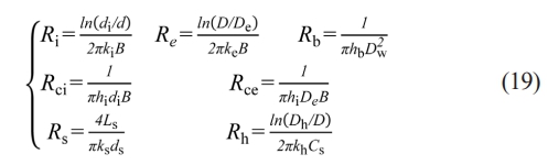
Figure 1 shows the deformation of the bearing under radial load. As seen in Fig. 1(b), the bearing undergoes vertical displacement when subjected to radial load:
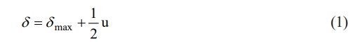
Where u/2 is the radial clearance between the rolling element and the outer raceway, and δmax represents the maximum deformation of the bottom rolling element. The deformation of the rolling element at any given angle can be derived based on the variability coordination condition:
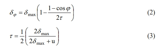
When the bearing is subjected to radial load, the contact load causes the deformation at point δφ to become zero at a certain limiting angle φ1. At this point, the value of angle φ1 is given by:
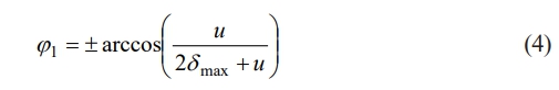
From the equation, it can be observed that the limiting angle φ1 < 90o indicates that the load-carrying region is less than 180°. According to Hertzian contact theory [25, 26], the relationship between deformation and contact load within this region is given by:
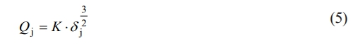
Where Qj represents the contact load of the j-th rolling element, K is the load–deformation coefficient, and δj denotes the deformation of the j-th rolling element.
From the above equation, it can be obtained that:
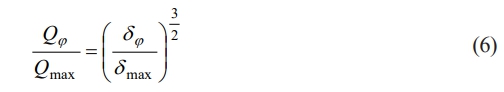
Where Qj and Qmax represent the contact loads of the rolling elements at position φ and the bottom position, respectively, and δj and δmax represent the deformations of the rolling elements at position φ and the bottom position, respectively.
The equilibrium equation for the rolling elements in the load-carrying region of the bearing is given by:
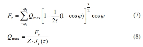
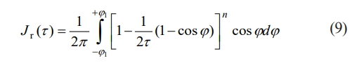
In the above equation, Jr(t) is the radial integral of the load distribution, and its expression is given as follows:
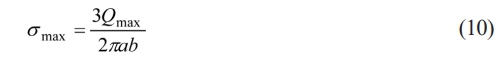
According to Hertzian contact theory, the contact area between the bearing rolling element and the raceway is elliptical in shape. The maximum contact stress occurs at the geometric center of this area, and its value is given by:
Heat Generation Calculation Model
The frictional torque is the main source of heat generation in the bearing. A frictional heat generation calculation model has been established to account for the stable operating characteristics of full ceramic bearings.
Frictional torque caused by differential sliding
At the contact point between the rolling element and the inner and outer races, frictional torque is generated due to the mismatch between the linear velocity of the rolling element and the linear velocity of the races. The energy loss resulting from this is given by:
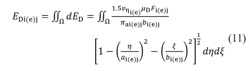
Under dry friction conditions, μD represents the contact friction coefficient between the rolling element and the raceway, with a value range of 0.4 to 0.7. νhi(e) is the relative velocity difference in the direction of differential sliding at the contact surface between the rolling element and the raceway. Ω is the elliptical contact area generated by the elastic deformation between the rolling element and the raceway after loading. i and e represent the inner and outer races, respectively;a and b are the semi-major and semi-minor axes of the elliptical contact area, respectively. The calculation formulas for these are given by:
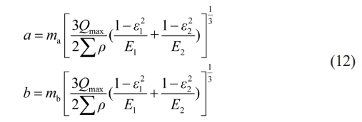
Where ma and mb represent the coefficients for the semi-major and semi-minor axes, respectively.
Frictional torque caused by spin sliding
The normal spin motion of the rolling element relative to the raceway generates spin friction, resulting in a spin frictional torque. The energy consumed by the j-th rolling element per unit time is given by:
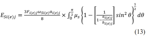
Where ωsi(e) is the spin angular velocity of the rolling element on the inner and outer raceways of the bearing. For dry friction, μs is the spin friction coefficient between solids, which ranges from 0.001 to 0.01.
Frictional torque caused by elastic hysteresis
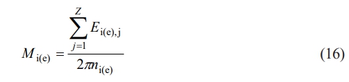
When the rolling element rolls on the inner and outer raceways, due to the elastic hysteresis properties of the material, a frictional torque is generated. The energy dissipated by the j-th ball after one load-carrying cycle is given by:
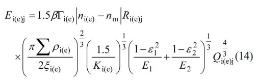
Where β is the elastic hysteresis loss factor; Γi(e) and ξi(e) are the first and second kinds of elliptical integrals, respectively; ni(e) and nm represent the rotational speeds of the bearing raceway and the rolling element, respectively; Ri(e),j is the distance between the contact point and the rotational axis of the rolling element; and Ki(e) is the ellipticity. Ki(e) = αi(e)/bi(e). Where αi(e) and bi(e) are the semi-major and semi-minor axes of the elliptical contact area, respectively; e1 and E1 are the Poisson’s ratio and Young's modulus of the rolling element, respectively; e2 and E2 are the Poisson’s ratio and Young's modulus of the bearing raceway, respectively; and Qi(e),j is the contact load of the j-th ball.
Frictional torque caused by the friction between the rolling element and the cage
When the rolling element rotates within the cage pocket, the normal contact load generates a frictional torque. The frictional torque is given by:
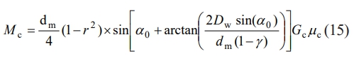
In the equation, dm is the pitch diameter of the bearing, α0 is the initial contact angle of the bearing, and γ is a dimensionless parameter. γ = Dw cos(α0)/dm. Gc is the weight of the cage, and μc is the sliding friction coefficient between the rolling element and the cage pocket, which ranges from 0.2 to 0.4.
According to the law of conservation of energy, the calculation formulas for the frictional torques of each component are as follows:
The internal temperature rise of the bearing is determined by the frictional torques of its components. The heat generation of the inner and outer races, Hi and He respectively, is given by:
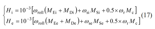
Where H is the generated heat, and ωroll is the rolling angular velocity of the rolling element. ωroll = ωc·dm/Dw. ωwc is the angular velocity of the cage, and ωr is the angular velocity of the rolling element's spin.
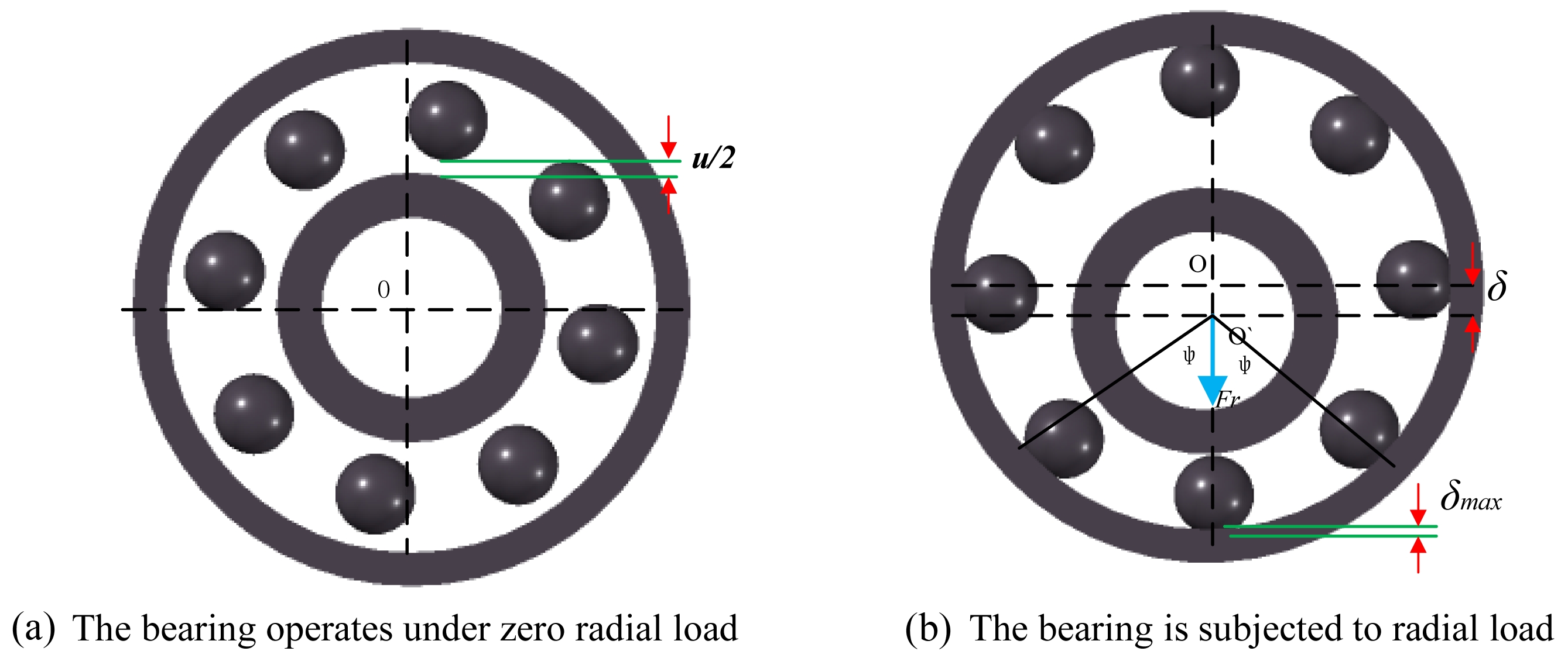
The heat generated by the bearing is split equally, with half entering the rolling elements and half entering the raceways [27, 28]. The heat transfer model for the ceramic balls at any azimuth is similar, so a one-dimensional model can be approximated to describe the heat transfer of the spindle unit. Fig. 2 shows the internal temperature node diagram and the thermal resistance network model of the deep groove ball bearing.
From Fig. 2, the heat transfer equations involving three unknown temperatures Tci, Tce, and Tb can be obtained as follows:
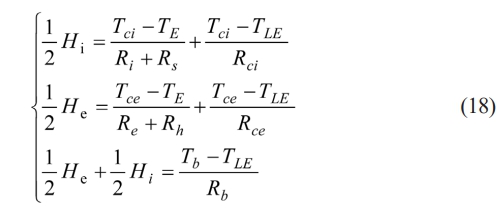
Where Tci is the surface temperature of the inner raceway; Tce is the surface temperature of the outer raceway; TE is the ambient temperature outside the bearing; TLE is the air temperature inside the bearing; Tb is the temperature of the rolling element; Ti is the inner surface temperature of the inner ring; Tc is the outer surface temperature of the outer ring; Ri is the thermal resistance of the inner ring; Re is the thermal resistance of the outer ring; Rci is the convective thermal resistance of the inner raceway surface; Rce is the convective thermal resistance of the outer raceway surface; Rb is the convective thermal resistance of the rolling element surface; Rs is the thermal resistance of the shaft; and Rh is the thermal resistance of the bearing housing.
The calculation formulas for each thermal resistance are as follows:
Where di and d are the outer and inner diameters of the inner ring, respectively; D and De are the outer and inner diameters of the outer ring, respectively; Dh and C are the outer diameter and width of the bearing housing, respectively; Dw and B are the ball diameter and the width of the bearing, respectively; Ls is the axial heat transfer length of the shaft; k is the thermal conductivity of each component; and h is the convective heat transfer coefficient.
Under dry friction conditions, the convective heat transfer medium around the bearing is air, and the average convective heat transfer coefficient between the internal bearing components and the heat transfer medium is given by:

Simulation Analysis of the Thermal Generation Model
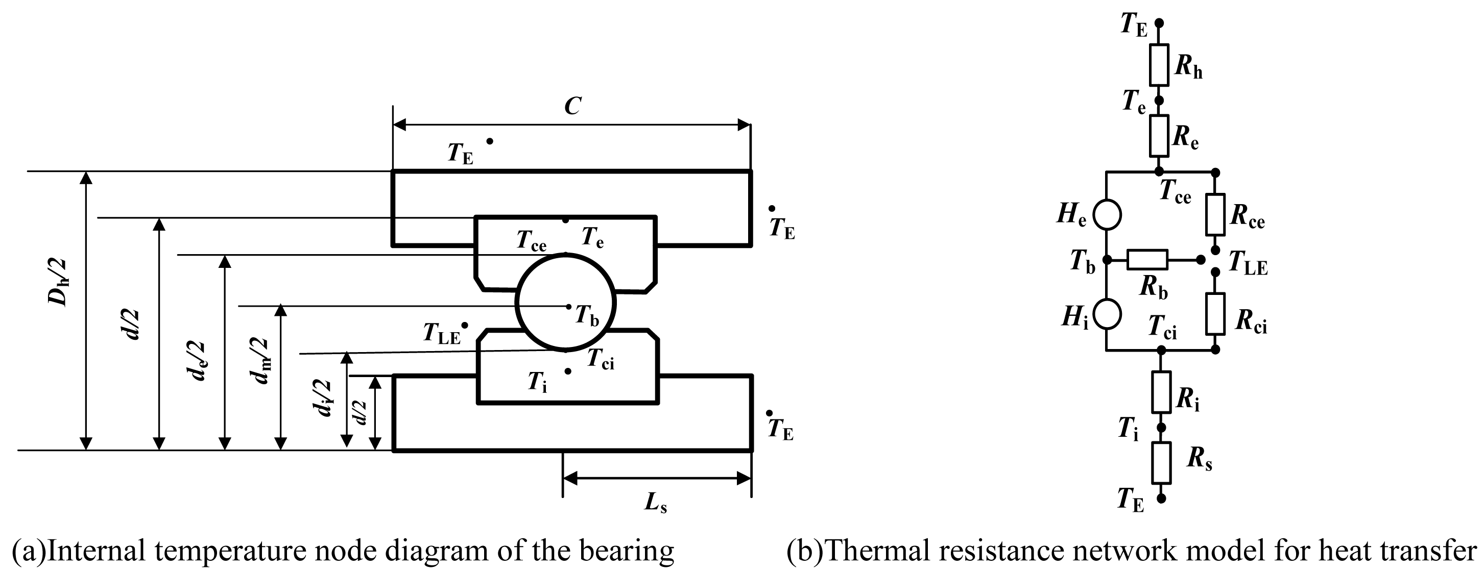
As shown in Fig. 3, these two graphs present the simulation results of the heat generation model for the 6206 silicon nitride full ceramic ball bearing.
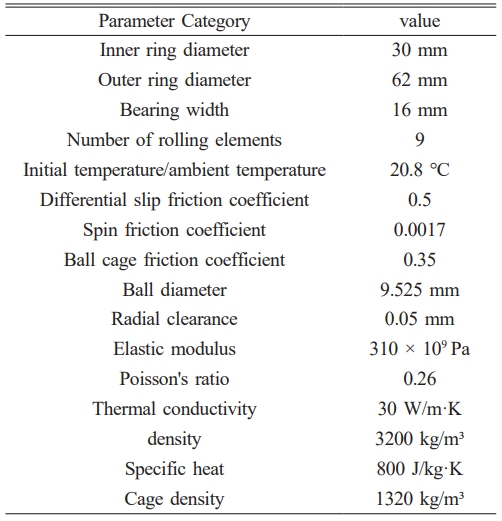
Figure 3(a) uses rotational speed as the horizontal axis and temperature rise as the vertical axis. Different color curves correspond to different loads (1350N–5350N), showing that as the rotational speed increases, the temperature rise increases for all loads, with a more significant temperature rise at higher loads (e.g., 5350N). Fig. 3(b) uses load as the horizontal axis and temperature rise as the vertical axis. Different color curves correspond to different rotational speeds (6000 r/min–10000 r/min), indicating that as the load increases, the temperature also rises at all speeds, with a greater temperature rise at higher speeds (e.g., 10000 r/min). Based on the simulation results for the 6206 silicon nitride full ceramic ball bearing, the temperature rise characteristics of this bearing can be summarized as follows: Rotational speed is the most sensitive factor influencing the temperature rise, with load being secondary. Under constant load, the temperature rise increases sharply as the speed increases (e.g., at 8000 r/min, the temperature rise can exceed 60 °C). Under constant speed, the temperature rise increases with the load, but the increase is slower. Other input parameters for the simulation, except for load and speed, are shown in Table 1.
The thermal model developed in this study is applicable under conventional operating conditions. However, under high-load or rotational speeds beyond the experimental range, the prediction results may contain some errors due to the extrapolation of material parameters and the insufficient consideration of thermo-mechanical coupling effects.
|
Fig. 1 Deformation of Deep Groove Ball Bearing under Radial Load. |
|
Fig. 2 Internal Temperature Node Diagram and Thermal Resistance Network Model for Heat Transfer in a Deep Groove Ball Bearing. |
|
Fig. 3 Variation of Temperature Rise under Variable Operating Conditions. |
|
Table 1 Basic parameters of 6206 all full ceramic deep groove ball bearing simulation calculation. |
Experimental Equipment
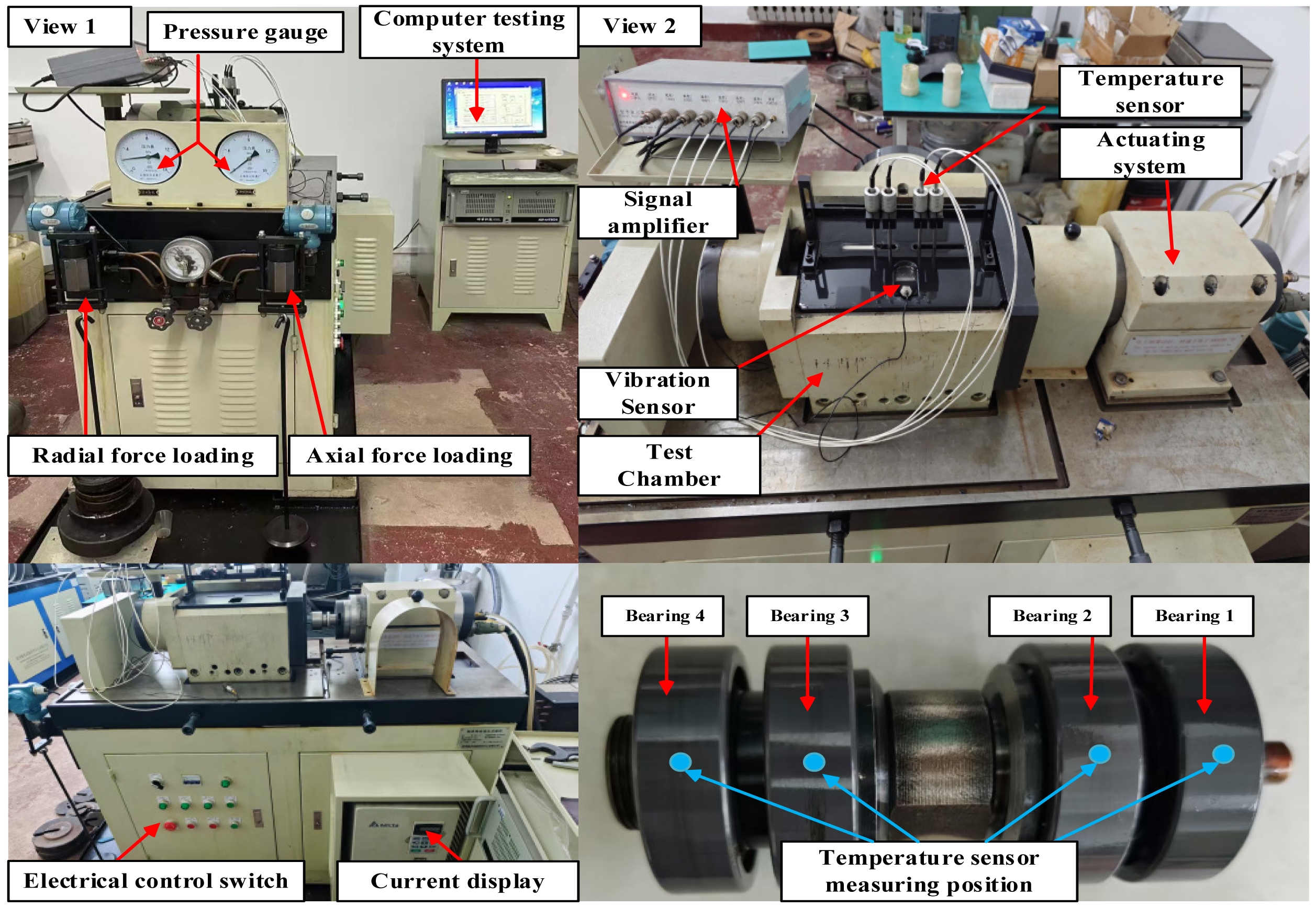
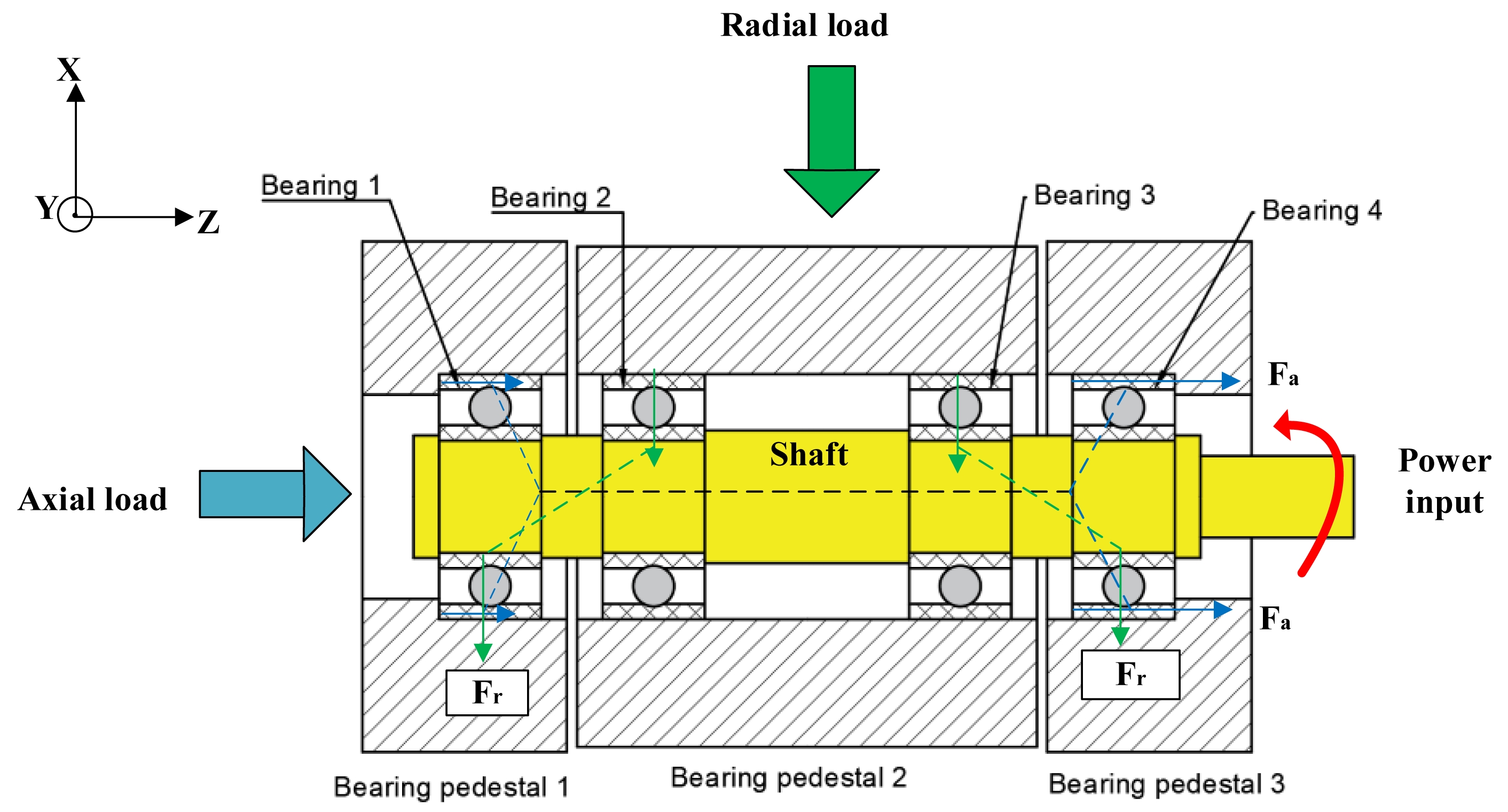
In order to study the full life thermal characteristics of full ceramic ball bearings, an ABLT-1A bearing life enhancement testing machine was used in this experiment, the main structure of which is shown in Fig. 4. The machine's radial load range is 0-30KN, and the maximum spindle speed is 18,000 r/min (when driven by the electric spindle, the speed is not less than 3,000 r/min). The motor is connected to the shaft via a coupling, and the motor speed can be independently set by a computer detection system. On the left side of the testing machine, there is a radial (axial) loading device, which allows the bearing to be loaded. The load application system supports independent or combined radial (Fr) and axial (Fa) loading modes. The load adjustment is achieved through a counterweight on the scale plate on the left side of the test bench. The mechanical transmission path is as follows: when axial load is applied to the test bearing via the axial loading device, the Fa is initially applied to bearing seat 1 and transmitted through the interface between the bearing outer ring 1, rolling element, and inner ring to the shaft system, which then acts on the associated bearing components. When radial load is applied to the test bearing via the radial loading device, the Fr is initially applied to bearing seat 2, and transmitted through test bearings 2 and 3 to the drive shaft system. The next stage distributes the load to test bearings 1 and 4 via the shaft structure. All four bearings in the test chamber are subjected to radial load, and the specific structure and stress analysis of the test chamber are shown in Fig. 5. The test system is equipped with a single-channel vibration monitoring unit (placed on the outside of the test chamber) and a four-channel temperature collection module (Bearing1-Bearing4), with spatial positioning shown in Fig. 4 (View 2). The temperature sensors are contact-mounted and pass through precision holes in the bearing seats to form a thermal conduction path with the corresponding bearing outer rings, enabling real-time monitoring of the surface temperature distribution on the outer rings. Bearings 1 to 4 correspond to the temperature parameters of the test bearings 1 to 4. By processing the temperature and vibration sensor signals (with the temperature sensors measuring the outer ring temperature) through amplifiers, real-time test data are recorded in the computer detection system for further analysis.
Experimental Plan
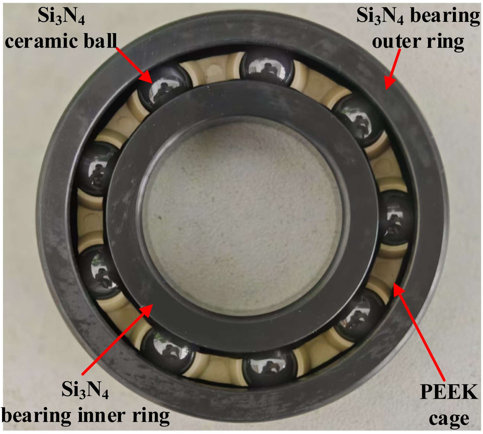
In this experiment, four 6206 silicon nitride full ceramic deep groove ball bearings from the same production batch were used. A full ceramic silicon nitride bearing refers to a bearing in which the inner ring, outer ring, and rolling elements are all made from silicon nitride ceramic material, while the cage is made of PEEK, as shown in Fig. 6. The four bearings were mounted together on the same shaft, with their installation positions illustrated in Fig. 5. The bearings in the test rig operated without lubrication. A radial load of Fr = 3.35 KN was applied, and the rotational speed was set to nr = 8000 r/min. This rotational speed falls within the common operating range of high-speed spindles and grinding applications, which not only reflects the thermal characteristics under practical working conditions but also ensures experimental safety and stability.
The bearings in the test assembly were numbered from right to left as Bearings 1 to 4, and then installed into bearing seats 1 through 3 in sequence. The assembled bearing unit was mounted into a custom bearing housing and placed in a sealed test chamber. The primary purpose of this test was to apply a radial load to the bearings. Since no axial load was applied, Bearings 1 through 4 all functioned as test bearings. In this experiment, temperature data were collected once per minute for each bearing.
In the experiment, we simultaneously collected vibration signals and bearing temperature data. However, the current study focuses primarily on temperature measurements, and the discussion emphasizes the response pattern of bearing temperature throughout the lifespan under unlubricated conditions.
|
Fig. 4 Bearing Life Enhancement Testing Machine. |
|
Fig. 5 Load Distribution Analysis in the Bearing Life Test. |
|
Fig. 6 Schematic Structure of the Test Bearing. |
Thermal Behavior Analysis throughout the Bearing’s Entire Service Life
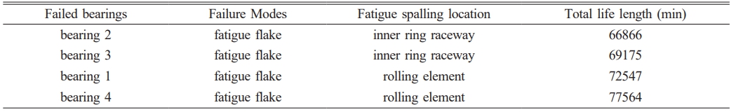
Since the primary focus of this full life bearing test was the steady-state temperature throughout the entire operation process, the test was concluded when Bearing 2 failed and caused the testing machine to shut down. Disassembly and inspection of the bearing after failure would lead to temperature fluctuations (e.g., a drop), making it impossible to connect the data before and after shutdown. Therefore, the test data were analyzed only up to the point of failure of Bearing 2. Prior to the shutdown, the average temperatures of the four test bearings were 47.81 °C, 48.33 °C, 47.92 °C, and 47.98 °C, respectively. Except for the failed Bearing 2, the temperature differences among the other three bearings were within approximately 0.2 °C, indicating stable thermal performance of the full ceramic bearings. The time to failure and shutdown caused by spalling in the test bearings is shown in Table 2.
A total of 66,866 data points were collected during the experiment. To better observe the trend of temperature variation over time, bearing temperature curves were plotted at intervals of every 3,000 minutes. The entire full life bearing test can be divided into three distinct stages: the initial run-in stage, the steady operation stage, and the bearing failure stage.
In bearing applications, heat generation primarily results from the relative motion between the cage and rolling elements, as well as between the inner and outer rings. Among these factors, bearing load and rotational speed have significant influence on bearing temperature [29, 30]. During the run-in stage, due to minor deviations in the internal clearances of newly installed ceramic bearings, interactions occur among components. On the microscopic level, surfaces of components such as rolling elements, cages, and rings may exhibit roughness and machining marks, resulting in higher friction during the run-in period. As the radial load increases, both the contact stress and contact frequency of the full ceramic bearing increase, which in turn raises the heat generated by friction and causes a rapid rise in the outer ring temperature.
In this study, polyetheretherketone (PEEK) was chosen as the material for the full ceramic bearing cage, primarily due to its advantages such as high-temperature stability, low friction coefficient, light weight, and corrosion resistance. Under high-speed rotating conditions, the PEEK cage reduces centrifugal force and frictional power loss, thereby decreasing the overall temperature rise of the bearing. Furthermore, the low-density characteristics of PEEK help improve the dynamic balance and vibration performance of the bearing.
It should be noted that due to the lower thermal conductivity of PEEK compared to metal materials, its heat dissipation performance is relatively weaker. However, within the load and speed range of this experiment, the impact of this factor on bearing temperature is not significant. Overall, PEEK material demonstrates a positive effect on the thermal characteristics of the bearing.
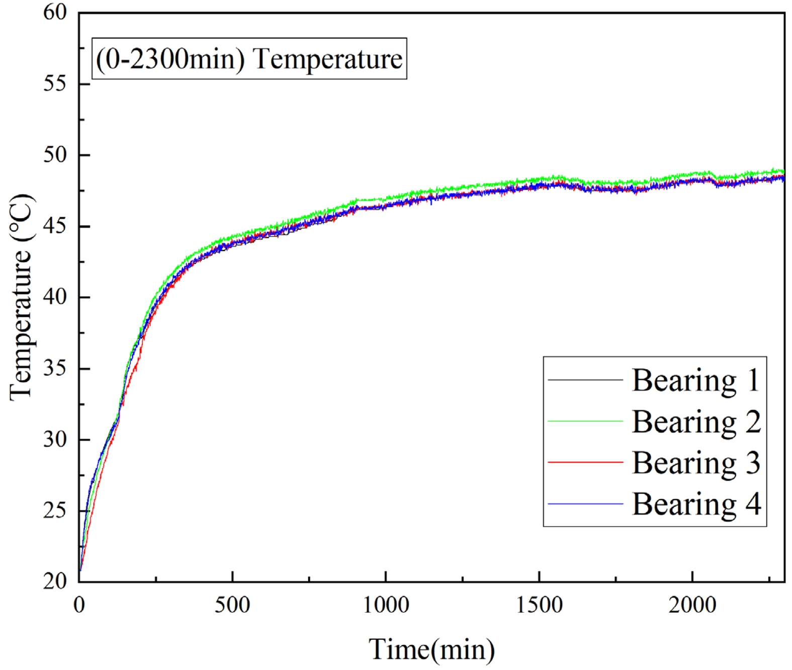
Based on the collected temperature data and visualized through data processing software, the run-in stage is illustrated in Fig. 7. The initial temperature during the test was 20.8 °C. The figure shows the temperature rise behavior of the silicon nitride full ceramic ball bearing during the start-up phase under a speed of nr = 8000 r/min, a radial load of Fr = 3.35 kN, and dry (unlubricated) conditions. Overall, the bearing temperature increased with load. The outer ring temperature exhibited a rapid heating period (0–300 min, with approximately linear increase), followed by a slower heating period (after 300 min, with continued rise at a reduced rate). Within the first 250 minutes, Bearing 4 showed a significantly faster temperature rise compared to the others, while Bearing 3 had the slowest. In terms of overall temperature, Bearing 2 was slightly higher than the other three (Bearings 1, 3, and 4), with minimal variation among the latter.
A stepwise incremental loading strategy was employed in this test (starting at 175 minutes, with load added every 30 minutes until reaching 876 minutes). After each loading step, a noticeable but short-lived temperature spike was observed, followed by a gradual stabilization. After the final loading step, the rate of temperature rise further slowed, reaching approximately 48.4 ℃ by 2300 minutes, where it gradually stabilized—marking the end of the run-in stage and the transition into a long-term steady operation stage characterized by minor temperature fluctuations.
Under the test conditions set for this experiment, the 6206 silicon nitride full ceramic ball bearing exhibited excellent thermal stability during the steady operation stage, with its temperature curve being relatively flat, maintaining a temperature range of 48 °C ± 1.3 °C. In contrast, the steel bearings under the same conditions showed a temperature range of 60–80 °C, with fluctuations of ± 5 °C. This comparison demonstrates that the temperature rise of silicon nitride full ceramic bearings is significantly lower than that of steel bearings, with superior thermal stability, confirming that the high thermal conductivity of silicon nitride material effectively promotes uniform heat dissipation.
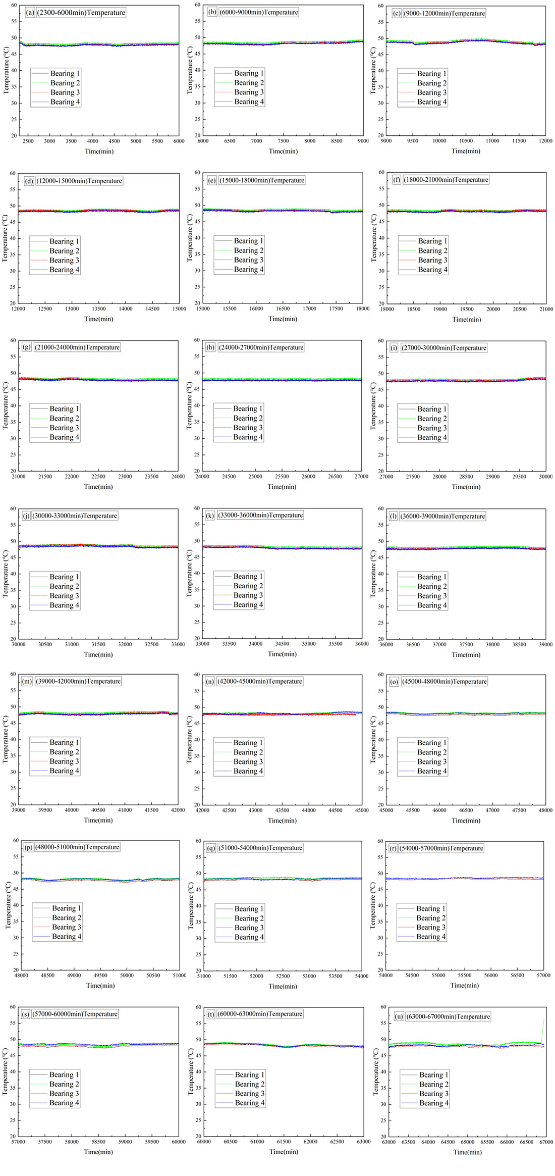
Furthermore, the temperature consistency among different groups (same model) of silicon nitride ceramic bearings was good, with temperature differences generally within 0.5 °C, showing minimal fluctuations and maintaining stability over extended periods (as shown in Fig. 8). Notably, during the steady operation stage, Bearing 2 exhibited a slightly higher overall temperature than the other three bearings, while the temperature difference between the remaining three bearings was very small, further reflecting the high consistency in performance among different bearing units.
Figure 8(u) shows the temperature rise curve during the fatigue failure stage of the silicon nitride full ceramic ball bearing. The test data indicate that around 66,550 minutes, the root mean square (RMS) and kurtosis of Bearing 2 showed abnormalities, and its temperature curve deviated significantly from the other three bearings, exhibiting a rising trend. Prior to this, when no abnormalities were observed in the test bearings, the temperature fluctuations of all four bearings were minimal, reflecting the excellent thermal stability of the silicon nitride full ceramic bearings.
After a cumulative operation time of 66,866 minutes, spalling occurred on the inner ring (nr = 8000 r/min, Fr = 3.35 KN, dry). This caused a sharp temperature change. By comparing the temperature with the other bearings, it was evident that the temperature increased significantly. The steady-state temperature of the inner ring was approximately 49 °C ± 0.3 °C before the spalling occurred, but within 1 hour, the temperature rose by about 7 °C, reaching 56.3 °C at the time of machine shutdown. This indicates that when partial spalling occurs in silicon nitride full ceramic ball bearings, it has a considerable impact on the bearing temperature.
Compared with dry friction, the introduction of lubrication can significantly reduce the frictional heat and contact temperature rise of the bearing, while also improving its overall heat dissipation characteristics.
The full ceramic bearing samples used in this study were all sourced from the same production batch to avoid additional uncertainties arising from batch differences. Multiple sets of independent repeat experiments were conducted under these conditions, with good consistency in the results, ensuring the reliability of the observed temperature variation trends. It should be noted that multiple batches of samples were not included in this phase of the study. Future work will involve further comparative experiments using samples from different batches to verify the generalizability of the conclusions.
|
Fig. 7 Temperature Evolution during the Bearing Run-in Phase. |
|
Fig. 8 Temperature Rise Curve after the Run-in Stage in the Full Life Test of Full Ceramic Ball Bearings. |
|
Table 2 Summary of Full Life Test Results for Silicon Nitride Full Ceramic Ball Bearings. |
In this study, a full life temperature rise test was conducted on silicon nitride full ceramic deep groove ball bearings under dry (unlubricated) conditions. By integrating theoretical analyses of bearing heat generation and heat transfer with real-time temperature monitoring using specialized data processing software, the thermal behavior and temperature rise characteristics of this type of bearing under extreme dry conditions were systematically revealed. Based on the comprehensive findings, the following key conclusions are drawn:
(1) During the run-in stage, the bearing temperature rose rapidly, indicating significant internal friction in the initial phase and highlighting the need for close monitoring during this period. After completing the run-in stage, the bearing temperature remained stable with narrow fluctuations over an extended period. The temperature differences among the test bearings were minimal, demonstrating good consistency and confirming the excellent thermal stability of full ceramic ball bearings, which provides a reliable foundation for their long term stable operation.
(2) Analysis of the temperature behavior over the full service life of silicon nitride full ceramic ball bearings shows that under a high radial load of 3.35 KN and high rotational speed of 8000 r/min, the temperature rise was only approximately 27.6 °C—significantly lower than that of conventional steel bearings. This fully demonstrates the low-temperature-rise characteristics of silicon nitride full ceramic ball bearings during operation. Furthermore, the full life temperature curve reveals that when cracks begin to form—prior to visible spalling—the bearing temperature shows a slight increase compared to the other test bearings. Once spalling occurs, a rapid and pronounced rise in temperature is observed.
(3) Based on the temperature data obtained from the full life test of full ceramic bearings, a comparison between the theoretically calculated temperatures and the experimental results was conducted to validate the feasibility of the heat transfer model for full ceramic bearings. Under the given test conditions, the deviation between the theoretical predictions and the experimental data was within 9%, further confirming the accuracy of the model.The primary sources of this error are experimental measurement uncertainties and simplifications in the model assumptions.
(4) After the full-life testing, no significant microstructural changes were observed in the silicon nitride material, even in the event of spalling. Only localized wear and surface damage were noted.
The authors acknowledge support from the National Natural Science Foundation of China (Joint Fund) Key Project (U23A20631), the National Key R&D Program of China (2024YFB3410202), the Liaoning BaiQianWan Talents Program, and the Open Fund Project of Liaoning Provincial Key Laboratory of Friction and Wear Materials for Aero-Materials (LKLAMTF202306).
- 1. W.I. Kwak, J.K. Lee, and Y.-B. Lee, Mech. Syst. Signal Process. 124 (2019) 424-438.
-

- 2. C. Fan, P. Wang, Y. Zhang, H. Ma, X. Li, and Q. Wang, IEEE Trans. Ind. Inf. 21[7] (2025) 5171-5181.
-
- 3. H. Shi, Y. Li, X. Bai, Z. Wang, D. Zou, Z. Bao, and Z. Wang, Mech. Syst. Signal Process. 149 (2021) 107317.
-
- 4. Z. Xia, Y. Wu, H. Wei, K. Ren, L. Gao, J. Sun, and S. Li, Shock Vib. 2021[1] (2021) 1176566.
-
- 5. M. Wang, K. Yan, Q. Tang, J. Guo, Y. Zhu, and J. Hong, Tribol. Int. 179 (2023) 108163.
-
- 6. S. Li, C. Li, M. Liu, Y. Wang, C. Zuo, H. Zhang, and Y Gao, J. Ceram. Process. Res. 24[6] (2023) 1025-1036.
-
- 7. M. Nosaka, M. Kikuchi, M. Oike and N. Kawai, Tribol. Trans. 42[1] (1999) 106-115.
-
- 8. B. Subramonian and B. Basu, Mater. Sci. Eng. A 415[1-2] (2006) 72-79.
-
- 9. P. Wang, S. Li, Y. Wu, and J. Zhao, J. Mech. Sci. Technol. 38[12] (2024) 6757-6767.
-
- 10. L. M. Keer and M. D. Bryant,J. Lubr. Technol. 105[2] (1983) 198-205.
-
- 11. R.S. Zhou, H.S. Cheng, and T. Mura, J. Tribol. 111[4] (1989) 605-613.
-
- 12. P. Wang, S. Li, Y. Wu, and J. Zhao, J. Ceram. Process. Res. 25[4] (2024) 694-703.
-
- 13. P. Wang, S. Li, Y. Wu, Y. Zhang, C. Wei, and Y. Wang, Appl. Sci. 14[2] (2024) 674.
-
- 14. C.C. Ye, H.Q. Ru, and D.L. Chen, Ceram. Int. 49[17] (2023) 28405-28414.
-
- 15. X.X. Han, C.H. Xu, H. Jin, W.H. Xie, and S.H. Meng, Sci. China Technol. Sci. 62[8] (2019) 1349-1356.
-
- 16. R. Rejitha, D. Kesavan, P. Chakravarthy, and S. Murty, Tribol. Int. 181 (2023) 108312.
-
- 17. L. Wang, R.W. Snidle, and L. Gu, Wear. 246[1-2] (2000) 159-173.
-
- 18. Z. Yang, T. Yu, Y. Zhang, and Z. Sun, Tribol. Int. 105 (2017) 125-134.
-
- 19. P. Wang, S. Li, Y. Wu, L. Zhang, C. Wei, Y. Wang, and G. Lin, Forsch. Ingenieurwesen 89 (2025) 73.
-
- 20. S. Lias, J. Zhao, Y. Wang, G. Lin, C. Wei, Z. Xia, C. Jia, and T Jing, J. Ceram. Process. Res. 26[3] (2025) 472-482.
-
- 21. J.W. Kannel and S.A. Barber, Tribol. Trans. 32[3] (1989) 305-310.
-
- 22. W.M. Hannon, J. Tribol. 137[3] (2015) 031102.
-
- 23. W.M. Hannon, T.A. Barr, and S.T. Froelich, J. Tribol. 137[3] (2015) 031104.
-
- 24. J. Sun, Z. Zhang, Z. Xia, X. Fang, R. Guan, G. Zhang, and J. Yao, J. Ceram. Process. Res. 24[3] (2023) 541-553.
-
- 25. Y. Jin, Z. Lu, R. Yang, L. Hou, and Y. Chen, Appl. Math. Mech. 39[3] (2018) 365-378.
-
- 26. S. Li, Mech. Mach. Theory 119 (2018) 61-73.
-
- 27. A. Baïri, N. Alilat, J.G. Bauzin, and N. Laraqi, Int. J. Therm. Sci. 43[6] (2004) 561-568.
-
- 28. X. Zhou, H. Zhang, X. Hao, X. Liao, and Q. Han, Tribol. Int. 130 (2019) 289-298.
-
- 29. C. Jin, B. Wu, and Y. Hu, Tribol. Int. 45[1] (2012) 8-15.
-
- 30. Y. Wang, S. Li, C. Wei, Y. Zhang, G. Lin, D. An, and J. Zhao, J. Ceram. Process. Res. 25[4] (2024) 643-659.
-
 This Article
-
2025; 26(6): 963-974
Published on Dec 31, 2025
- 10.36410/jcpr.2025.26.6.963
- Received on Jul 21, 2025
- Revised on Sep 19, 2025
- Accepted on Oct 2, 2025
Services
- Abstract
introduction
heat generation model of full ceramic bearings
full life testing of silicon nitride full ceramic ball bearings
results and discussion
conclusion
- Acknowledgements
- References
- Full Text PDF
Shared
Correspondence to
- Pengfei Wang
-
School of Intelligent Manufacturing, Panzhihua University
Tel : +86-18382106635 Fax: 0812-3371017 - E-mail: 18382106635@163.com
Clean-Energy Research Institute(CRI), Hanyang University, 222, Wangsimni-ro, Seongdong-gu, Seoul, 04763, Korea
E-mail: jcpr@hanyang.ac.kr