


- Study on the scratching force surface damage morphology of SiCf/SiC composites by single abrasive grain with ultrasonic assistance
Xuezhi Wanga,b,c,*, Hanying Wanga,c, Ming Conga,b, Wenbo Fand and Na Yuane,*
aSchool of Mechatronics Engineering, Shenyang Aerospace University, Shenyang 110136, China
bAECC Shenyang Liming Aero-Engine Co., LTD, Shenyang 110043, China
cKey Laboratory of Rapid Development & Manufacturing Technology for Aircraft (Shenyang Aerospace University), Ministry of Education, Shenyang 110136, China
dTeaching and Research Support Center Army Artillery and Air Defense Forces Academy, Shenyang 110065, China
eSchool of Information and Control Engineering, Liaoning Petrochemical University, Fushun 113001, ChinaThis article is an open access article distributed under the terms of the Creative Commons Attribution Non-Commercial License (http://creativecommons.org/licenses/by-nc/4.0) which permits unrestricted non-commercial use, distribution, and reproduction in any medium, provided the original work is properly cited.
Continuous silicon carbide fiber reinforced silicon carbide matrix composites (SiCf/SiC) are used in many different industries, including aerospace, due to their high hardness, high temperature, and resistance to oxidation, corrosion, and wear. However, when machining SiCf/SiC composites, problems such as matrix rupture, edge chipping, fiber warping and pull-out, and tool wear are prone to occur. This paper conducts a finite element scratching simulation study on SiCf/SiC composites, which is validated through experiments to investigate the matrix and fiber damage destruction mechanism and to meet the demand for high-quality, high-efficiency machining of SiCf/SiC composite structural components. Findings indicate that the scratching force increases with scratching speed, scratching depth, and ultrasonic amplitude increase. However, with the rise of the scratching angle, the scratching force tends to increase and then decrease. In addition, single-particle scratching experiments showed that matrix fragmentation, fiber breakage, fiber debonding and detachment, and matrix debonding between fibers were the primary manifestations of SiCf/SiC composite damage. In the case of ultrasonic vibration scratching, the scratch morphology is high-frequency impact scratches, and the vertical fiber fracture is neat. These findings clarify the fundamental damage and removal mechanisms of SiCf/SiC composites and provide a useful reference for optimizing machining parameters to enhance processing quality and efficiency.
Keywords: SiCf/SiC composites, Ultrasonic-assisted grinding, Grinding mechanism, Abaqus finite element simulation.
Continuous silicon carbide fiber-reinforced silicon carbide matrix composites (SiCf/SiC) are a new type of toughened ceramic matrix composite. With the benefits of elevated temperature tolerance, hardness, oxidation resistance, corrosion resistance, and abrasion resistance, which have numerous uses in the aerospace industry [1-5]. The SiCf/SiC composites were prepared using a fiber bundle braiding process, which provides excellent compatibility between the fibers and the matrix since they belong to the same material [6-9]. This effectively deflects the expansion path of matrix microcracks and allows effective stress transfer between the fibers and the matrix. Compared to laminated composites, SiCf/SiC composites exhibit superior mechanical performance [10]. However, the high hardness and wear resistance of SiCf/SiC ceramic matrix composites pose significant challenges in machining, including excessive tool wear and elevated cutting forces [11-13]. During machining processes, defects such as cracks, crush fractures, delamination, fiber warping, and fiber pull-out are prone to develop [14]. The issues severely compromise machining quality and limit application in high-temperature environments [15]. For precise machining of SiCf/SiC composites, ultrasonic-assisted grinding processing has emerged as the most promising processing technique [16-19]. Compared with ordinary grinding processing, the axial ultrasonic vibration applied to grinding tool alters abrasive grain trajectories, and interaction between the grinding tool and the workpiece shifts from a continuous mode to an intermittent one, which reduces the tool wear and also reduces surface and subsurface grinding damage while enhancing the integrity of the machined surface [20-25].
Over the past few years, research on ceramic matrix composites that are ground with ultrasonic assistance has increased. Bertsche et al. [26] compared the effect of conventional and ultrasonically assisted grinding on SiCf/SiC composites, contrasting machined surface roughness, grinding force, and wheel wear under the two grinding methods, and found that, in contrast to the traditional grinding approach, ultrasonic vibration enhances the grinding process performance and efficiency. Using a homemade PCD tool, Xiong et al. [27] tested SiCf/SiC composites using a homemade PCD tool with ultrasonic vibration-assisted milling and found that tool wear in the form of grain abrasion and grain exfoliation, the ultrasonic vibration induces high-frequency stress interactions between the tool and the grains, cause grain fracture, and give the ultrasonic vibration parameters that can achieve a smaller grinding force and longer tool life. Qiao et al. [28] a grinding force model for longitudinal–torsional ultrasonic vibration-assisted machining was proposed by analyzing the kinematics of abrasive grains and incorporating the effective number of active grains, as determined through measurement and analysis. They discovered that at low spindle speeds, the impact of torsional vibration is more pronounced; however, at small grinding forces, the effect of the change in the removal mode of material is affected, and the model predictions are more inaccurate and less accurate. Liu et al. [29] diamond-coated milling cutters were utilized to machine C/SiC composites under both conventional milling and ultrasonic vibration-assisted milling conditions, revealing that abrasive wear is the predominant wear mechanism and coating delamination is the primary cause contributing to wear. Jin et al. [30] discovered that compared with normal grinding and pure longitudinal ultrasound, longitudinal-torsional coupled vibration significantly altered the motion trajectory with abrasive grains during grinding of SiCf/SiC composites, resulting in an improvement in grinding surface and a notable reduction in the wheel grinding force. Current research has focused on tool life in SiCf/SiC composite grinding, although the mechanism for material removal is still insufficiently deep. At the microscopic level, the synergistic removal mechanism with fiber and matrix is still unclear. Additionally, precisely controlling the machining parameters to achieve optimal machining quality and efficiency is still an urgent problem. These issues prevent SiCf/SiC composites from being used more widely in aerospace and other industries, so in-depth investigation into grinding and machining characteristics holds significant practical relevance.
Focusing on the physical properties and processing requirements of SiCf/SiC composites, this study establishes a three-dimensional scratching simulation model using Abaqus and constructs an ultrasonic vibratory scratching test platform to investigate the mechanisms of material damage and removal. Comparative experiments with a diamond indenter under conventional and ultrasonic-assisted conditions reveal how scratching parameters influence the scratching force, providing insights into the machining characteristics of SiCf/SiC composites. Although based on single-grain scratching, the identified damage mechanisms—matrix fragmentation, fiber fracture, and interfacial debonding—are consistent with those observed in large-scale grinding and milling, suggesting that these micro-scale findings may be cautiously extended to multi-grain machining scenarios. Overall, this work contributes to the mechanistic understanding of material removal in SiCf/SiC composites and offers certain implications for the optimization of machining parameters, mitigation of damage, and improvement of machining quality and efficiency in practical applications.
SiCf/SiC composites are anisotropic inhomogeneous materials incorporating orthogonally braided SiC fiber bundle reinforcing phases [31]. To effectively demonstrate the characteristics of the prepared fiber bundles and ensure the computational results accurately represent the fiber bundle scratching simulation process, this chapter will establish a 3D model for scratching simulation.
In the scratching simulation of SiCf/SiC composites, factors such as scratching parameters and the physical properties of the indenter may exert a significant influence on the results [32]. As the primary objective of this study is to examine the effect of scratching parameters on the scratching force, secondary factors were reasonably constrained or disregarded. The simulation model was therefore set up as follows:
(1) Define the diamond indenter as a rigid body. Owing to its exceptionally high elastic modulus and hardness, the contact stresses generated during scratching are well below the threshold for measurable elastic deformation or plastic damage. Defining the indenter as a rigid body enhances computational efficiency and eliminates errors associated with elastic coupling.
(2) Neglecting the impact of scratching temperature on the SiCf/SiC composite model structure. The contact duration in single-particle scratching is extremely short, and the high thermal conductivity of SiC facilitates rapid dissipation of heat. Under the present conditions, the interfacial temperature rise is minimal and does not significantly affect the mechanical response of the material, even at elevated scratching speeds.
(3) To ensure the accuracy of scratching depth, surface of SiCf/SiC composite model is defined as a plane.
(4) The vibration problems of the indenter and the SiCf/SiC composite model are ignored.During the experiment, both the indenter and the specimen were fixed within a high-stiffness fixture, which effectively suppressed macroscopic structural oscillations. The residual microscale vibrations are substantially smaller than the dominant loading response and have no appreciable influence on the overall stress distribution.
Parameters and constitutive modeling of SiCf/SiC composites
The construction of material constitutive models aims to fully reflect the adaptability and dynamic properties of materials to the external loading environment [33]. Currently, the JH-2 model stands as the most widely employed constitutive model in investigations into hard and brittle materials such as SiC [34].
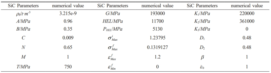
The JH-2 model focuses on describing material processes from the onset of yielding to the final destruction due to the superposition of failures. This model was applied to the simulation and analysis of the SiC cutting mechanism and obtained more satisfactory research results [35]. In this paper, the application of the JH2 intrinsic model to simulate the SiC matrix and SiC fiber fracture process will be simulated through the invocation of the ABAQUS subroutine. The parameters are shown in Table 1.
The standardized equivalent force equation expression for the JH2 model is
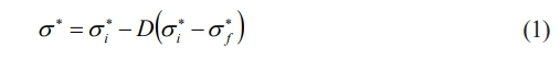
σ*i is undamaged equivalent strength. σ*j is fully damaged equivalent strength, D is damage parameter. The range is between 0 for no damage and 1 for complete damage.
Undamaged equivalent strength is
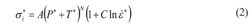
Complete damage, equivalent strength can be articulated as
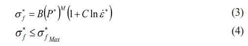
A, B, C, M, N, T denote fitting parameters, which can be obtained experimentally, σ*f max is the equivalent strength at maximum crushing, P * is standardized pressure, T * is standardized maximum equivalent hydrostatic tensile force, ε̇* is equivalent strain rate, where P *, T *, and ε̇* can be derived from the following equation:
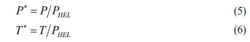

P indicates hydrostatic pressure, PHEL is pressure at elastic limit of Hugoniot, T is maximum tensile hydrostatic pressure, ε̇ is true strain rate, ε̇0 is reference strain rate.
For the damage parameter D, the formula is
∆εP is plastic strain in one cycle, εfP is fracture plastic strain at pressure P.
εfP can be expressed as

where D1 and D2 are damage factors.
Hydrostatic pressure in the unbroken state is

K1 is bulk modulus, K2, K3 is equation of state parameter, m is specific volume of material and can be expressed as

ρ is current density, ρ0 is initial density.
For tensile stresses, when μ < 0, expression for hydrostatic pressure is

With the progressive accumulation of damage, the material undergoes volumetric dilation, resulting in an increased hydrostatic pressure. The increment of hydrostatic pressure is denoted as ∆P, and expression for hydrostatic pressure is

There is no increment in hydrostatic pressure when D is 0. When D is 1, ∆P is at its maximum.
If the energy loss in the material is converted into hydrostatic pressure potential energy through a parameter P, the approximate expression for the energy conversion equation is
β is a constant and ∆U is the amount of energy lost.
Therefore, the constitutive equation can be formulated as
When creating the material properties, input the SiC material mechanical parameters required for JH-2 constitutive model, and rest of material parameters can be calculated from Table 1 displays the specific parameters.
Complex physical and chemical interactions exist between the matrix and reinforcing phases of composites. Dugdale [36] proposed the theory of interfacial cohesion in 1960 in response to the problem with interfacial properties of composite materials and accordingly described relevant properties for material interfaces. The failure of the two-phase interface of a composite material is mainly manifested when the material is subjected to stresses exceeding the damage criterion of the interface, and the damage starts and gradually evolves until the cohesion completely disappears. In the Abaqus software platform, a common method to simulate the two-phase contact behavior of composites is to use the cohesive unit. The stress-strain response of the unit can be defined by the failure criterion. This simulation is chosen using the maximum principal stress criterion, and the interface model was established, whose expression is shown in Eq. (16).
Where σn, σs, and σt are stress components and σnMax, σsMax, and σtMax are the maximum stress components.
The damage separation criterion for cohesive units is

Where D is the overall damage, which goes from 0 in the absence of damage to 1 in the presence of complete damage; and ε͞͞n , ε͞͞s and ε͞͞s are the stress components in the absence of damage.
The unit attribute parameters are shown in Table 2.
Modeling and meshing
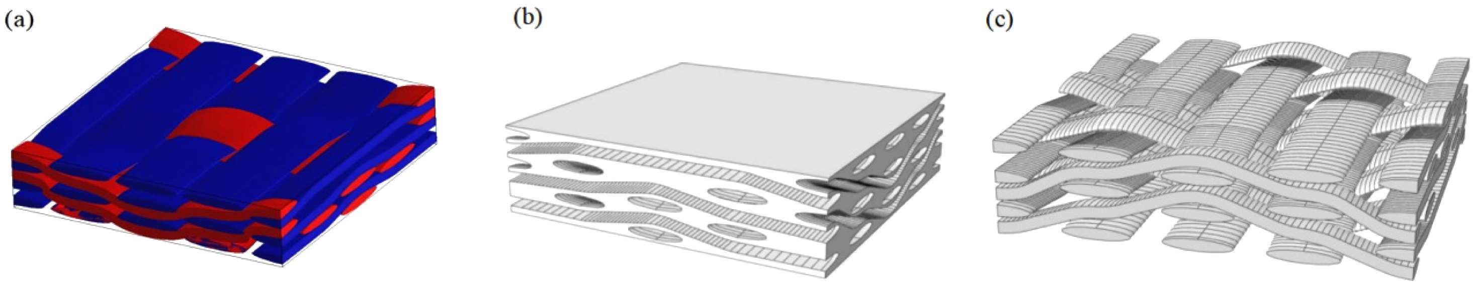
SiC fibers, an interfacial layer, and a SiC matrix make up SiCf/SiC composites [37]. Using the Digimat platform for SiCf/SiC composites modeling, set the fiber bundle orthogonal braiding form and volume fraction. For SiCf/SiC composites with fiber volume fraction of 39.88%, a three-dimensional geometric model was constructed with dimensions of 6.6 mm in width and length and 1.73 mm in thickness. The exported STP format file was imported into Abaqus finite element analysis software and scaled by a factor of 1000 to obtain a correctly dimensioned SiCf/SiC composite model, as shown in Fig. 1.
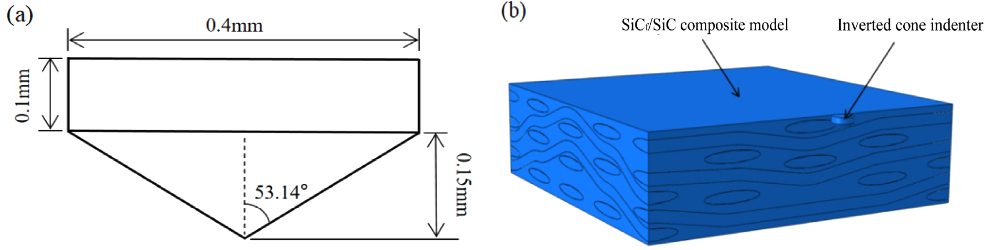
Construct the geometric model of the diamond indenter. The shape of the diamond indenter is an inverted cone. The specific dimensions of the height of the bottom of the indenter are 0.25 mm, the maximum diameter of the indenter is 0.4mm, and the angle formed by the conical bus and the center axis is about 53.14. The height of the conical section at the bottom of the indenter is 0.15 mm, and its structure is shown in Fig. 2.
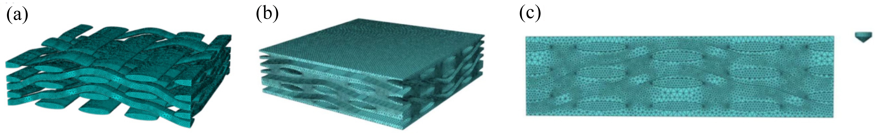
To ensure numerical stability and computational efficiency, a free mesh discretization was adopted, with the SiCf/SiC composite model meshed at an overall element size of approximately 0.05 mm. Four-node tetrahedral elements (C3D4) were employed to improve the stability of explicit analysis and to prevent numerical issues associated with excessive mesh refinement. The macroscopic model dimensions are 6.6 mm × 6.6 mm × 1.73 mm, with an effective scratching length of 6.6 mm, as shown in Fig. 3. After the model database was established, the system automatically generated a non-editable initial analysis step; therefore, an additional Dynamic Explicit step was introduced to implement boundary conditions and other related settings. Mass scaling was selectively applied in this step to reduce the computational time while preserving the key response characteristics [38].
Parameter settings and simulation results
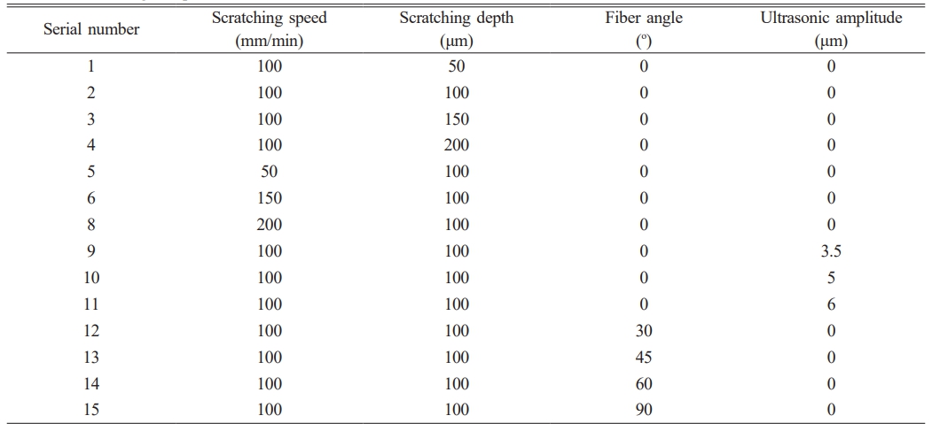
In the parameter settings, the fiber angle was selected as 0, 30, 45, 60, and 90 for the typicality of the fiber angle and the accuracy of the clamping, respectively, and the parameters of the scratching depth, scratching speed, scratching angle, and ultrasonic amplitude appear in Table 3.
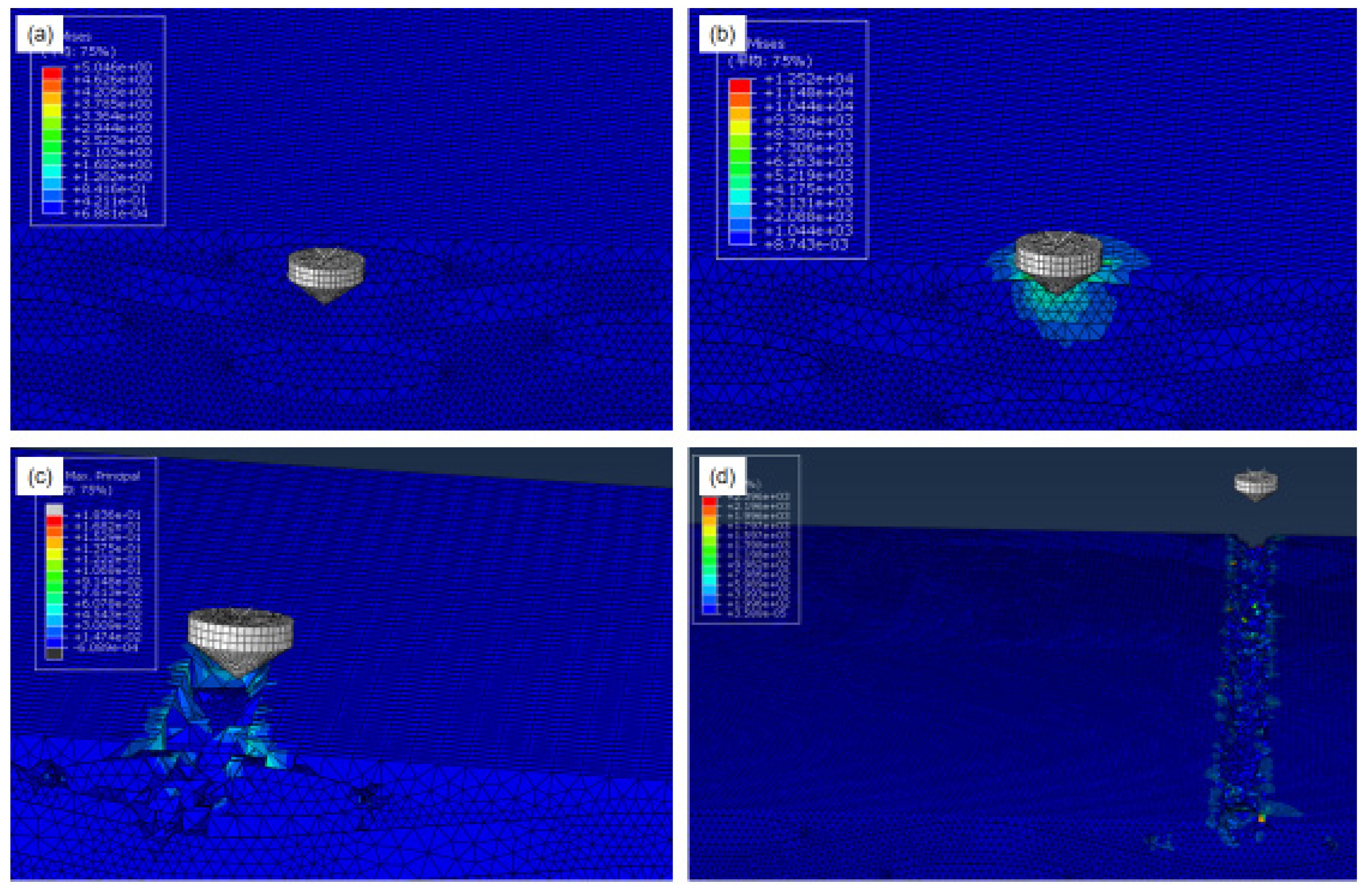
Fixed constraints are applied to the bottom surface of the workpiece, translational and rotational degrees of freedom of the indenter are restricted and reference point of the indenter is set with the established X-direction velocity and displacement; during the ultrasonic scratching simulation, the Z-direction cyclic displacement is applied to the model of the indenter on the basis of the X-direction displacement, and the instantaneous value of which is determined by the relation α=A, 2πf·t, to reach simulation of the ultrasonic scratching process. Fig. 4 depicts the scratching simulation computation procedure.
As seen in Fig. 4, in initial phase, the indenter has not yet contacted the material surface and is in an uncut state. As the indenter moves along the X direction and applies displacement, it enters the initial stage of cut-in, and the indenter begins to contact the material surface, and the local stress gradually accumulates, leading to small plastic deformation and initial cracks in the matrix. Stresses in the contact area as the indenter penetrates further into the material can exceed the compressive strength of the substrate, which triggers matrix crushing and crack expansion. Eventually, in the indenter cut-out phase, the scratching force decreases rapidly, leaving scratches on the surface caused by matrix fragmentation, fiber breakage, and interface debonding.
|
Fig. 1 Geometrical model of the SiCf/SiC composite: (a) preliminary 3D model; (b) SiC matrix; (c) SiC fiber bundle. |
|
Fig. 2 Simulation model of diamond indenter scratching on SiCf/SiC composites: (a) inverted cone indenter; (b) scratching simulation model. |
|
Fig. 3 Mesh division of the simulation model: (a) SiC fiber bundles; (b) SiC matrix; (c) overall structure. |
|
Fig. 4 Scratching simulation calculation process: (a) indenter not cut in; (b) indenter cut in initial phase; (c) indenter cut in phase; (d) indenter cut out. |

Materials and Tools
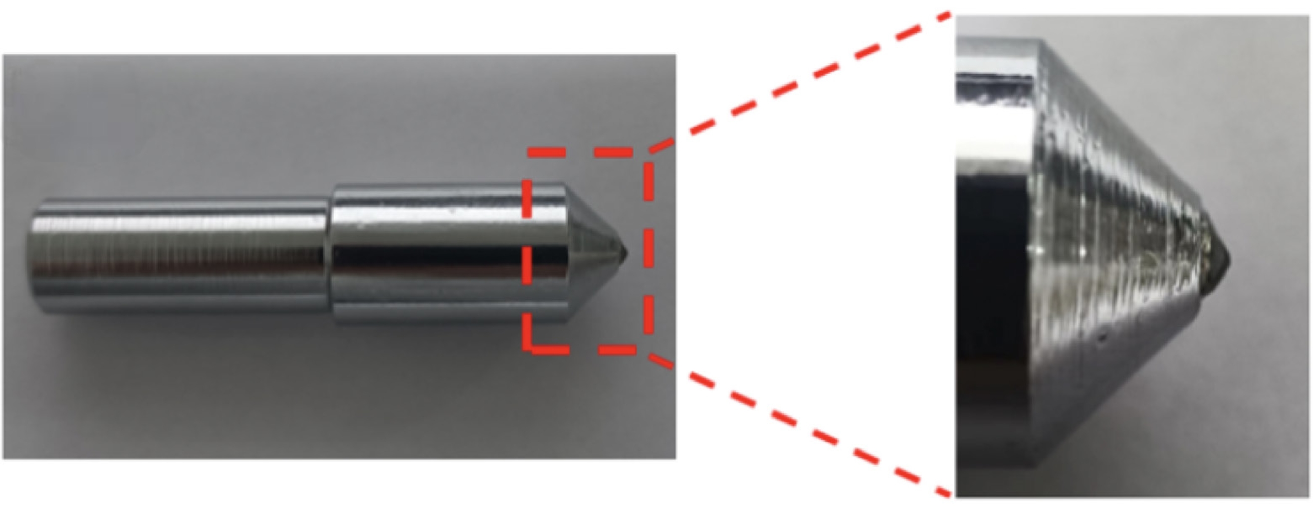
The structure of the diamond indenter selected for this scratch test is shown in Fig. 5, which is mainly composed of an inverted cone-shaped diamond particle embedded at the end of the indenter, and its tail is designed as a cylinder measuring 20 mm in length and 10 mm in diameter, which is fixed to the ultrasonic shank through threaded clamping to ensure that the ultrasonic vibration energy can be transmitted with optimal efficiency.
Test platforms and test parameters
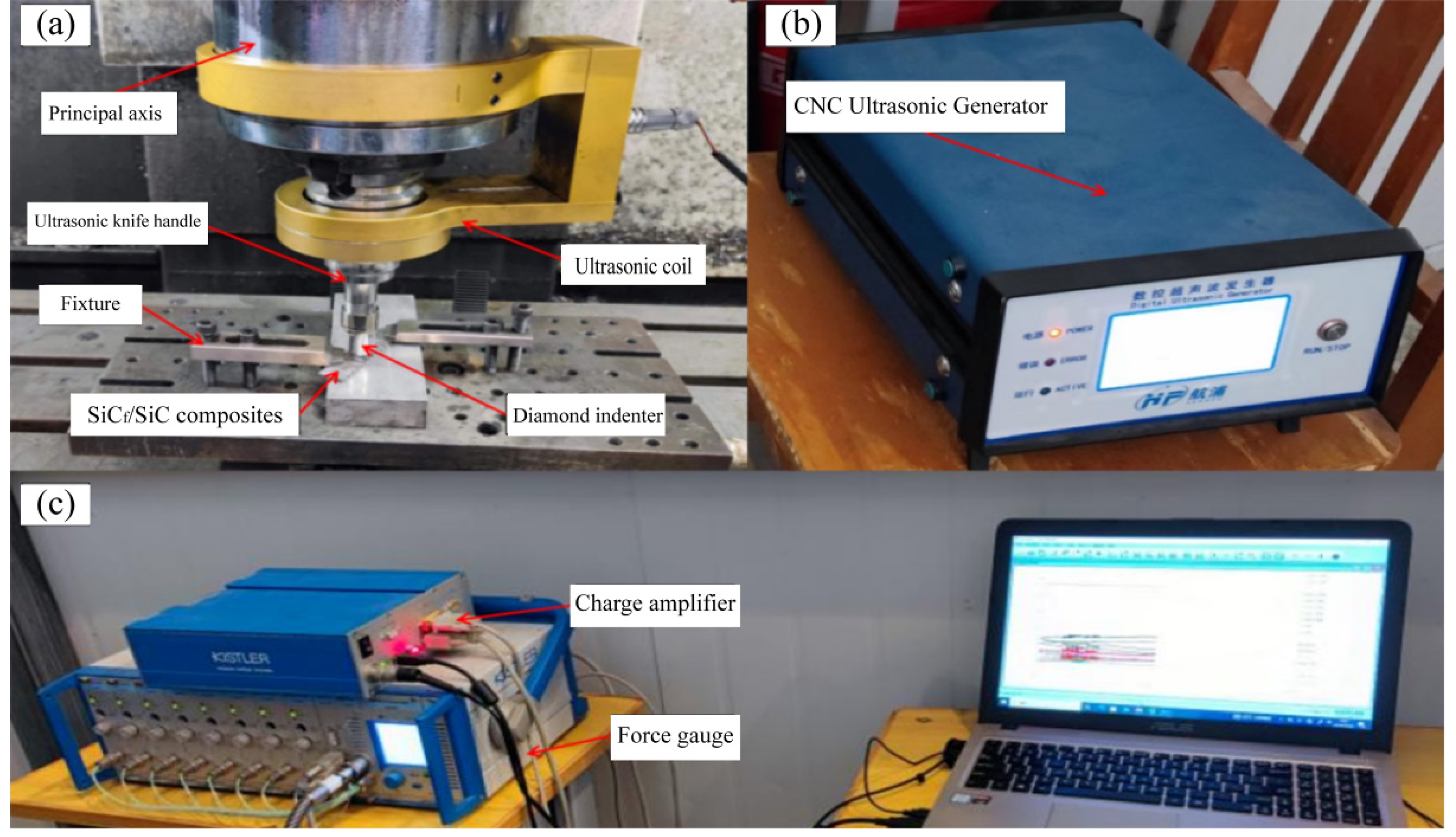
As Fig. 6 illustrates, the ultrasonic vibratory scratch test rig for SiCf/SiC composites was constructed on a vertical machining center, VMC 850B. The fixture was bolted to the platen, and the SiCf/SiC composites were fixed to pad iron. The diamond indenter only makes uniform linear motions throughout the scratching test, so before the scratching test starts, use CNC commands to enable the machine spindle to lock the rotational freedom of the tool holder. The shank selected for the test is an ultrasonic power shank, and the start and stop of the axial vibration of the shank are controlled to realize the ultrasonic vibration scratching and ordinary scratching, and the ultrasonic vibration energy in the test comes from the external numerical control ultrasonic generator. In the ultrasonic vibration scratching test, an ultrasonic generator converts the industrial-frequency electrical signal into a high-frequency signal, and simultaneously, the ultrasonic vibration energy is transferred to coils fixed in the spindle and transmitted to the secondary coils in the ultrasonic shank by inductance, and an axial high-frequency vibration impact is produced on workpiece surface by the diamond indenter attached to ultrasonic tool holder. By adjusting ultrasonic generator output power using the touch interface, the ultrasonic amplitude can be changed.
Scratching force is measured using a KISTLER 9257B force gauge and a 5067 charge amplifier, as shown in Fig. 6(c). The force-measuring instrument was mounted on the machining center table to collect the signal from the scratching force and transform it into a faint electrical signal. Finally, the scratching force signal was displayed on the computer using the DynoWare software platform. Before the scratching test, the surface scratching depth beginning position was determined by adjusting longitudinal displacement of indenter while observing real-time change of the Z-direction force signal in the force gauge software.
In this study, the normal scratching test and the ultrasonic vibration scratching test are conducted respectively, the frequency of the axial ultrasonic vibration is set at 19 kHz, and it is perpendicular to the workpiece scratching surface. The one-factor scratching experiment was conducted by varying the scratching parameters, and the scratch force signal was simultaneously acquired. To verify the simulation results, the scratching depth, scratching speed, scratching angle, and ultrasonic amplitude are consistent with the simulation parameters. Due to the low electrical conductivity of the material, the workpiece is ultrasonically cleaned and then sprayed with gold, after which the scratches of each scratch parameter group are observed by scanning electron microscopy.
|
Fig. 5 Diamond indenter. |
|
Fig. 6 Scratch test platforms: (a) ultrasonic vibratory scratch platforms; (b) ultrasonic generators; (c) force signal acquisition equipment. |
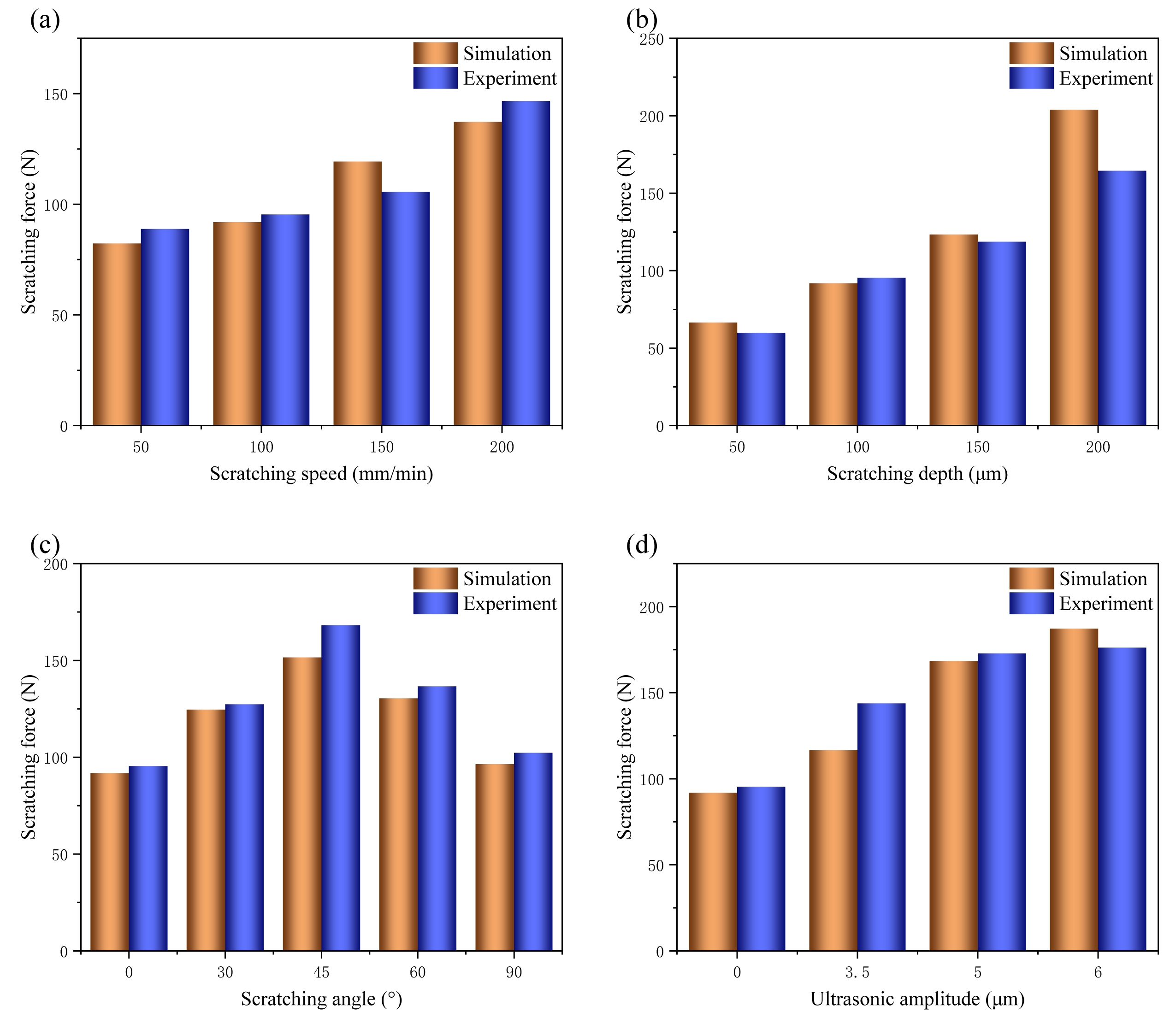
Effect of scratching parameters on scratching force Experimental and simulation results show that there is a significant correlation between the scratching parameters and the scratching force. As illustrated in Fig. 7(a), both simulated and experimental scratching forces increase with the scratching speed under conditions of constant scratching depth (100 μm), fiber orientation angle (0°), and ultrasonic amplitude (0 μm). The scratching force that was simulated and experimental rose from 82.27 N and 88.82 N at 50 mm/min to 137.2 N and 146.68 N at 200 mm/min, respectively.
The scratching depth, as depicted in Fig. 7(b), also exerts a significant impact on scratching force. With constant conditions of scratching speed (100 mm/min), fiber orientation angle (0°), and ultrasonic amplitude (0 μm), increasing the depth from 50 μm to 200 μm results in a greater scratching force from the simulation of 66.53 N and the test of 59.93 N to 203.87 N and 164.4 N, respectively. According to the analysis, when the scratching depth increases, so does the contact area between the indenter and the workpiece, which raises the indenter resistance during the scratching process. Consequently, increasing the grinding depth in SiCf/SiC composite processing not only elevates the grinding force but also tends to induce defects such as crushing and crack propagation.
Fig. 7(c) shows the effect of scratching angle on the scratching force. Under a constant scratching speed (100 mm/min), depth (100 μm), and zero ultrasonic amplitude, the force first increases and then decreases with angle. From 0° to 45°, both experimental and simulated forces rise, while beyond 45° they gradually decline and return to the level at 0°. The peak at 45° results from diagonal scratching, which simultaneously engages fibers and matrix, thereby expanding the contact area and generating a more complex stress state. This interaction promotes the combined action of shear, plowing, and fracture mechanisms, ultimately increasing the scratching force. In contrast, at 0° or 90°, the tool scratches mainly parallel or perpendicular to the fibers, so that scratching is dominated by either the fibers or the matrix, producing lower resistance. Similar angle-dependent behavior, with intermediate orientations yielding higher resistance, has been observed in other orthogonally braided composites, suggesting a general rule. Thus, to optimize stress distribution and reduce grinding forces in SiCf/SiC machining, the grinding head should cut along orthogonal fiber directions (0° or 90°).
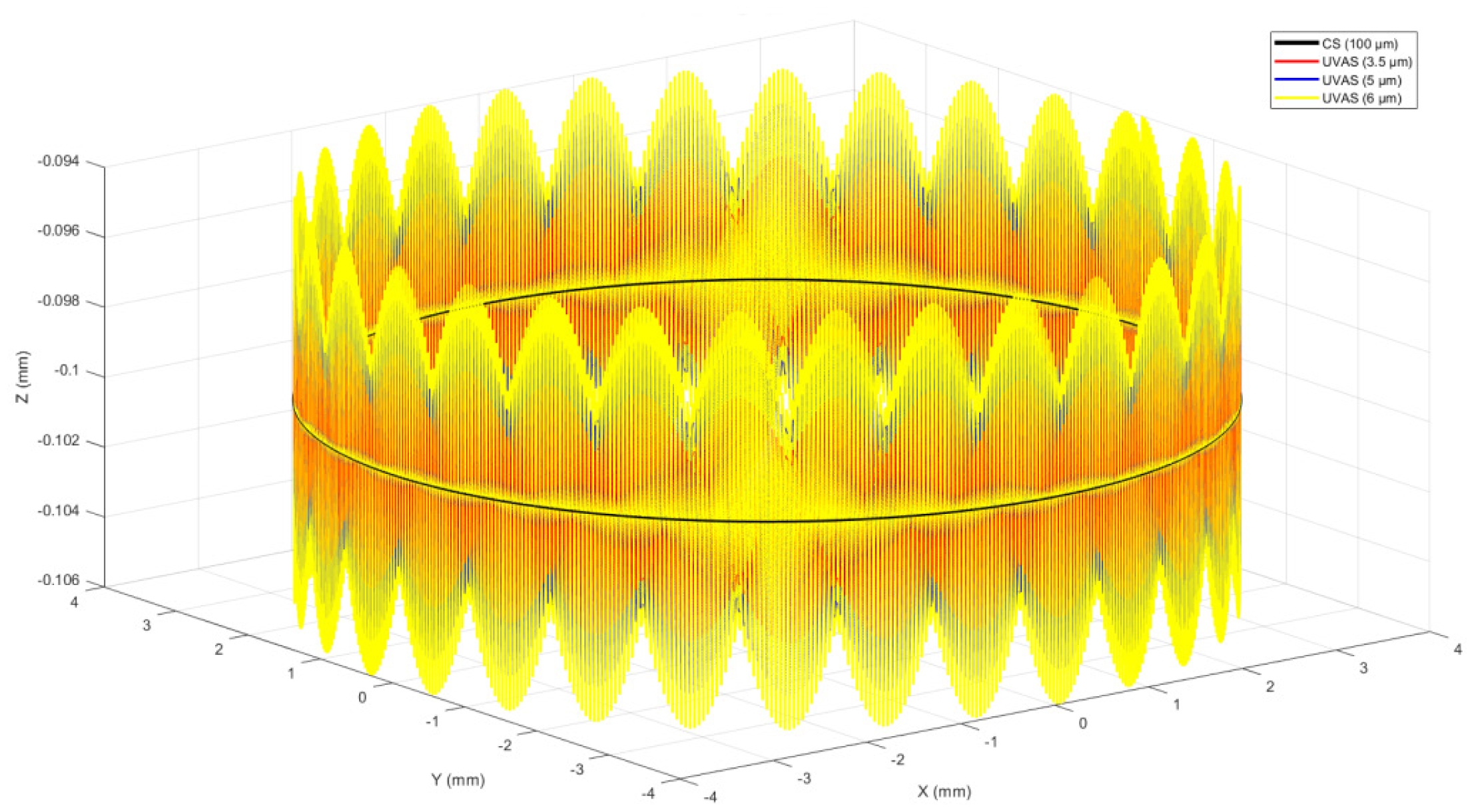
Illustrates Fig. 7(d) , under constant scratching speed (100 mm/min), scratching depth (100 μm), and fiber orientation angle (0°), the amplitude increases from 0 μm to 6 μm, and the scratch force increases from the simulated 91.87 N to 187.18 N, which is consistent with the experimental result that the scratch force increases from 95.42 N to 176.2 N, indicating that the scratching force grows as the ultrasonic amplitude increases. Analysis shows that ultrasonic vibration of the diamond indenter in the Z direction can cause periodic changes in scratch depth, as shown in Fig. 8. Ultrasonic vibration increases the depth of the indenter along the Z direction, and the increase is equal to the amplitude. Increasing scratch depth will lead to an increase in scratch force, so an increase in ultrasonic amplitude will lead to an increase in scratch force.
Although the simulation and experimental results demonstrate a consistent overall trend, deviations are observed under certain parameter conditions. These discrepancies mainly arise from three aspects. First, the finite element model assumes an idealized flat surface for the composite, whereas the actual specimens may exhibit surface roughness, local non-uniformities, and exposed fibers. Such variations modify the effective contact area between the indenter and the workpiece, leading to differences in the measured force. Second, real SiCf/SiC composites contain pores, interfacial defects, and microcracks that reduce local strength, while the numerical model presumes a uniform and defect-free structure. This simplification becomes particularly significant at greater scratching depths, where stress concentrations amplify the influence of internal defects. Third, uncertainties in the experimental setup—such as fluctuations in ultrasonic energy transmission efficiency, limitations in sensor sensitivity, and background signal noise—introduce additional errors. Overall, the observed deviations are primarily attributed to the contrast between the idealized assumptions of the numerical model and the structural and environmental complexities of the actual experiments.
Effect of scratching mode on the surface morphology of SiCf/SiC composites
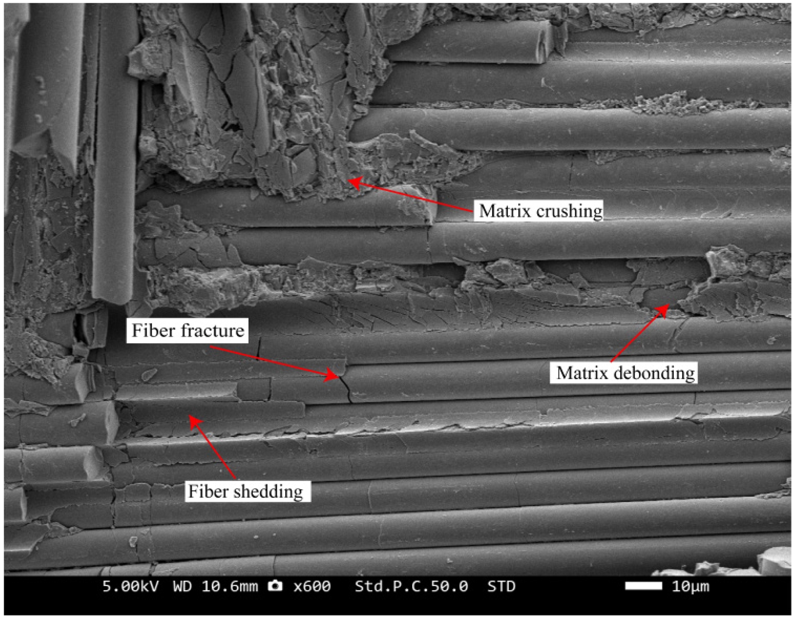
In Fig. 9, the morphology of scratch marks on the SiCf/SiC composite subjected to conventional scratching is depicted. By analyzing SiCf/SiC composite removal forms, brittle and ordinary hard materials are found to have significantly somewhat different removal mechanisms. In SiCf/SiC composites, material removal is involved in the brittle fracture behavior of the SiC matrix and the toughening effect of the SiC fiber, which together define the removal mechanism. At the initial stage of scratching, the SiCf/SiC composite undergoes slight plastic deformation due to the combined extrusion and shear forces applied by the indenter. The deeper the indenter goes, the more the role of the material and the indenter contact area of the corresponding rise in stress, cracking and crushing of the matrix will occur when the stress surpasses the substrate compressive strength. Subsequently, the indenter continues to penetrate deeper, the interfacial layer between the fiber and matrix experiences crack propagation and eventual debonding, the SiC fibers brittlely fracture and are stripped [39].
There are SiC fibers parallel and perpendicular to the direction of scratching because the reinforcing phase of material is created by the orthogonal weaving of SiC fiber bundles [40]. In the direction of scratching, the form of this scratching test is a unidirectional straight-line scratching, and the indenter does not have the same way of acting on the fibers in these two directions. Therefore, the damage of parallel and perpendicular fiber bundles on the track of the scratching needs to be observed and categorized to discuss the damage. The fiber and scratching direction schematic is shown in Fig. 10.
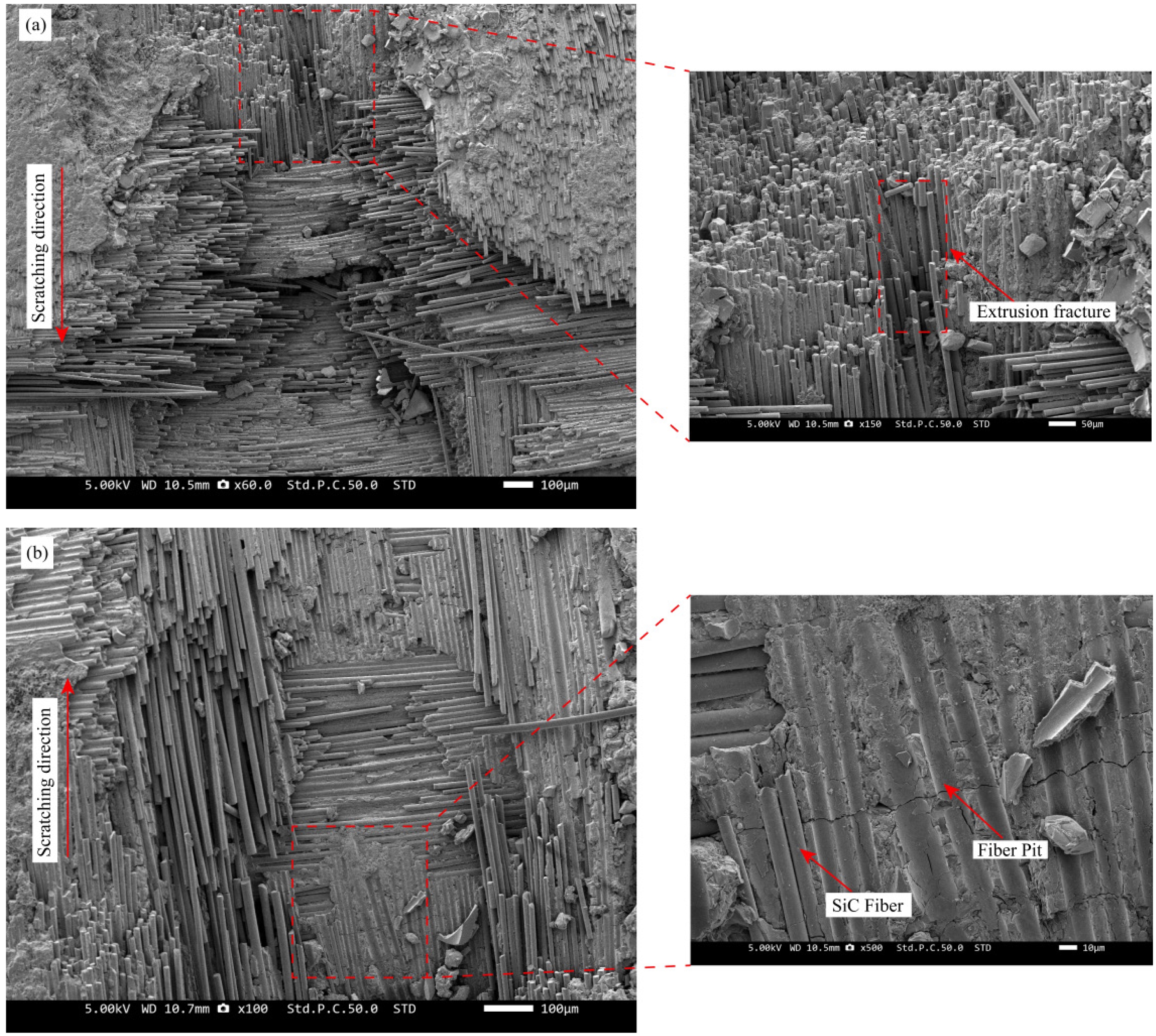
As demonstrated in Fig. 11(a), the material removal mechanism of SiC fibers predominantly manifests as brittle fracture induced by coupled tensile-compressive stresses. During this process, fiber bundles oriented parallel to the scratching direction exhibit a well-defined hierarchical step-like feature. As observed in Fig. 11(b), the SiC fibers were detached from the substrate after fracture, leaving semi-cylindrical crater marks on the surface of the substrate. At the same time, the indenter formed deep and narrow scratches where the action direction was parallel to fiber orientation [41, 42].
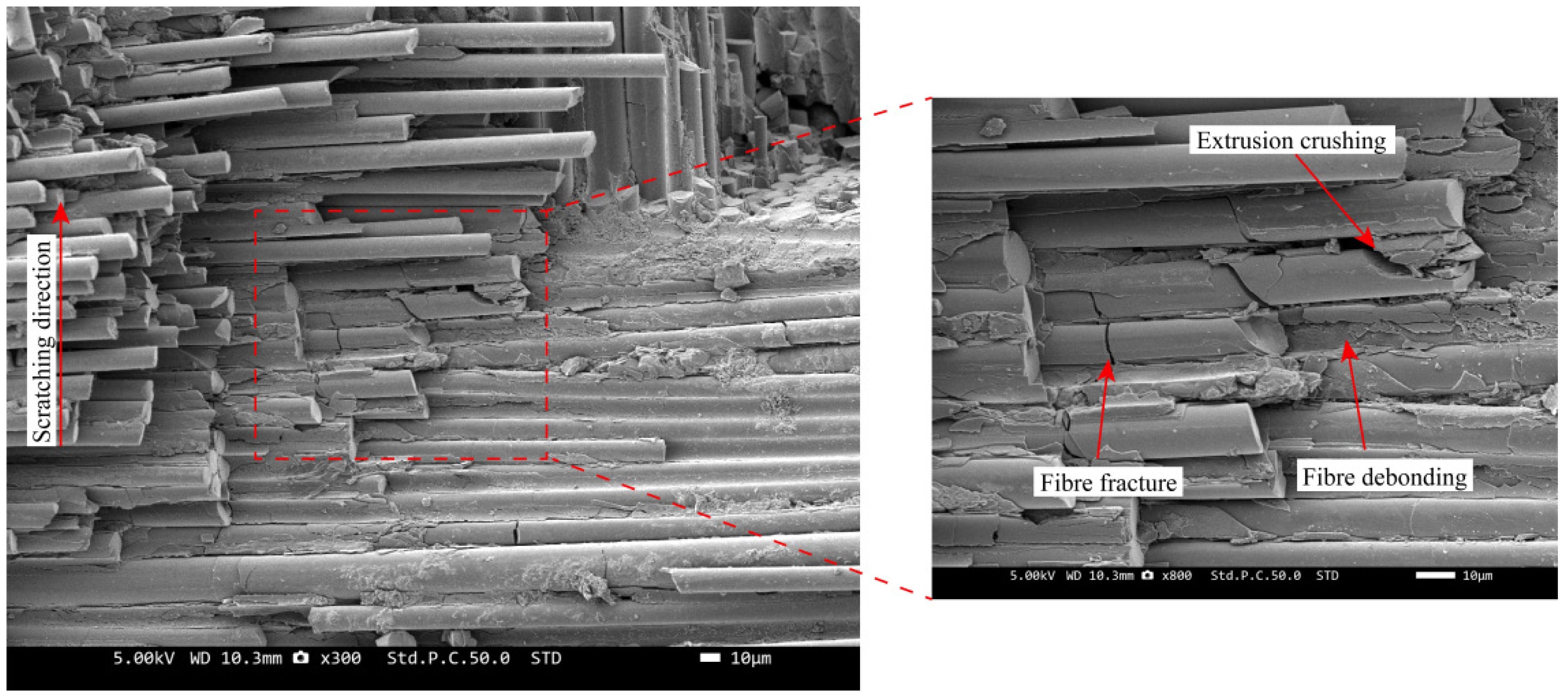
Scratch morphology of fiber bundles oriented perpendicular to the scratching direction is shown in Fig. 12, indicating that the primary method of material removal is extrusion-induced matrix and fiber crushing, as well as fiber breakage and shedding. For SiC fibers in the perpendicular scratching direction, the indenter breaks them mainly by shear force and, under shear and extrusion forces, separates fibers on either side of indenter from the matrix.
Furthermore, compared to fibers aligned with the scratching direction, scratch profiles generated by the action of the indenter on fibers oriented perpendicularly exhibit reduced depth and increased width.
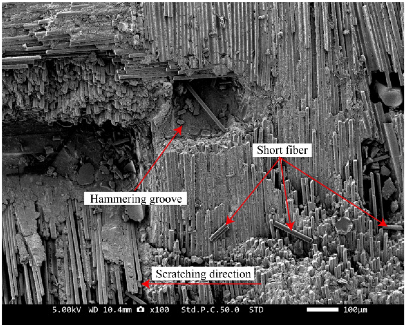
Fig. 13 displays the scratch morphology of SiCf/SiC composites created in an ultrasonic vibratory scratching test at a frequency of 19 kHz, which is characterized by high-frequency impact scratches caused by ultrasonic vibration. The cause of the phenomenon is the indenter, subjected to high-frequency longitudinal vibration during scratching, making intermittent contact with the workpiece surface [43]. Similar to ordinary scratching, ultrasonic vibration scratching damage is mainly manifested as fiber breakage, matrix fragmentation, fiber debonding, and shedding. It is worth noting that the new scratch features produced by ultrasonic vibratory scratching include hammering grooves caused by the ultrasonic vibration and shorter chips formed by the breakage of SiC fibers.
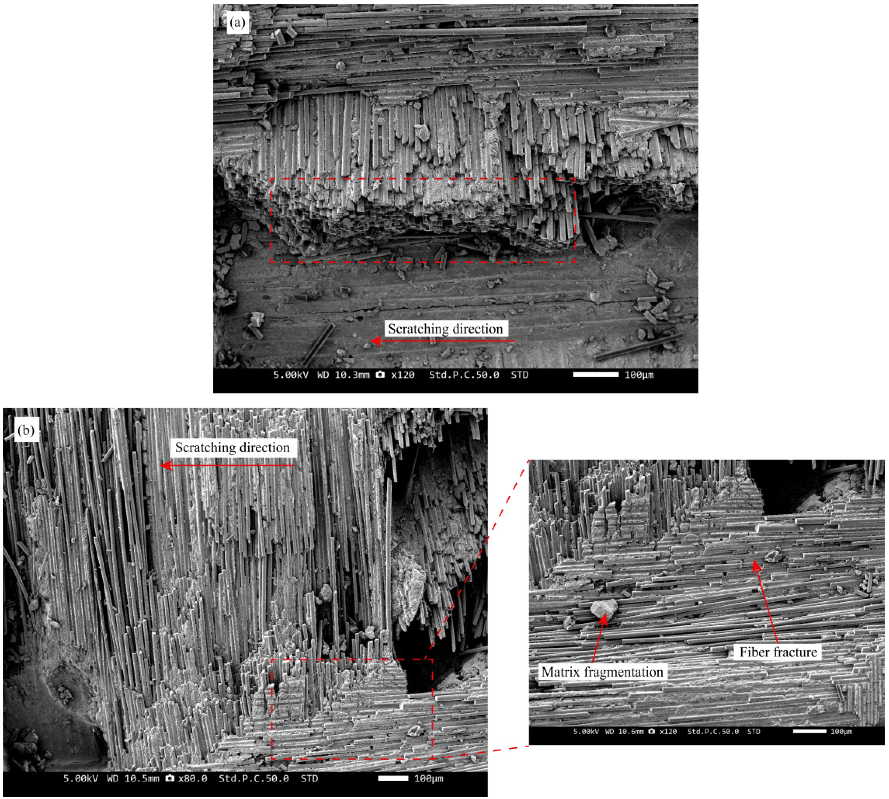
The morphology of scratches after ultrasonic vibratory scratching is discussed separately according to the fiber direction. Following the ultrasonic vibratory scratching test, the scratch morphologies of fibers oriented perpendicular and parallel to scratching direction are distinctly illustrated in Fig. 14(a) and (b), respectively. As is evident from Fig. 14(a), compared to ordinary scratching, the perpendicularly oriented SiC fiber bundles subjected to ultrasonic vibration scratching exhibit a flat fracture surface due to the dressing effect induced by the longitudinal vibration of the indenter. Fig. 14(b) reveals that fibers aligned parallel to the scratching direction are truncated into numerous short fibers under sustained ultrasonic hammering, while the matrix is shattered into smaller debris for enhanced removal efficiency.
|
Fig. 7 Effect of scratching parameters on scratching force: (a) scratching speed; (b) scratching depth; (c) scratching angle; (d) ultrasonic amplitude. |
|
Fig. 8 Schematic diagram of tool paths with and without ultrasonic vibration scratching. |
|
Fig. 9 Qrdinary scratching morphology. |

|
Fig. 10 Fiber and scratching direction schematic. |
|
Fig. 11 Parallel direction: (a) fiber extrusion fracture; (b) fiber stripping concave pits. |
|
Fig. 12 Vertical direction scratch morphology. |
|
Fig. 13 Ultrasonic vibration scratch morphology. |
|
Fig. 14 Fiber fracture morphology: (a) vertical direction; (b) parallel direction. |
In this paper, for the SiCf/SiC composites, which are prone to edge chipping, fiber breakage, and warpage in traditional machining, the ultrasound-assisted machining technology is utilized and combined with finite-element simulation analysis to explore the phenomena. Used ABAQUS finite element analysis software to establish a three-dimensional scratching simulation model of SiCf/SiC composites and built an ultrasonic vibration scratching test platform. By comparing the scratching force data following normal machining and ultrasound-assisted machining, the simulation model validity was validated. Additionally, the influence law of each scratching factor on the scratching force was investigated.
(1) The increase in scratching speed, scratching depth, and ultrasonic amplitude all lead to increased scratching force. In addition, the scratching angle increases from 0° to 90°, and the scratching force exhibited a tendency to grow and then drop, peaking at 45° and minimizing at 0° and 90°.
(2) Compared with the traditional unidirectional fiber composites and 2D SiCf/SiC composite models, the 2.5D SiCf/SiC composite cutting model is closer to the actual scratching process. The correctness and dependability of the model are demonstrated by the analysis of the error between the simulation and test values, which finds that the error is often within 20%, which is relatively small.
(3) Both conventional and ultrasonic vibration-assisted scratching tests were conducted on SiCf/SiC composites, and the post-scratch morphologies of the matrix and fibers were examined using scanning electron microscopy. Matrix fragmentation, fiber breakage, fiber debonding and detachment, and inter-fiber matrix debonding were the primary forms of material damage. Fibers aligned parallel to the scratching direction fracture under predominant compressive stresses, generating deep and narrow scratch profiles, whereas fibers oriented perpendicular to the scratching direction fail primarily through shear-dominated stresses, producing shallow yet broadened scratch morphologies.
(4) During ultrasonic vibratory scratching, high-frequency axial vibration of the indenter produces intermittent hammering that causes the fibers oriented perpendicular to the scratching direction to exhibit neat breaks. Toward the direction of the scratching, the fiber is hammered into short fibers and removed, which is significantly different from the damage characteristics of ordinary scratching.
This work was funded from the fundamental research funds for the universities of Liaoning province (LJ212410143043, LJ222410143059, LJ232410143042), the Project Supported by the Foundation of Key Laboratory of Rapid Development & Manufacturing Technology for Aircraft (Shenyang Aerospace University) (JYBSYS202409) and the two machine special project (J2022-VII-0005-0047).
- 1. Z.C. Li, Y. Jiao, T.W. Deines, Z.J. Pei, and C. Treadwell, Int. J. Mach. Tools Manuf. 45[12-13] (2005) 1402-1411.
-

- 2. Y. Ran, J. Sun, H. Sun, R. Kang, Z. Dong, and Y. Bao, Int. J. Mech. Sci. 287 (2025) 109926.
-
- 3. Y. Chai, H. Zhang, X. Zhou, and Y. Zhang, Ceram. Int. 44[2] (2018) 2165-2169.
-
- 4. X. Shen, M. Li, Y. Dai, X. Zhou, and P. He, Ceram. Int. 46[9] (2020) 13088-13094.
-
- 5. Y.-S. Jeong, H.G. Yoon, and K. Choi, J. Ceram. Process. Res. 24[5] (2023) 841-849.
-
- 6. W. Guo and Y. Gao, J. Ceram. Process. Res. 24[2] (2023) 379-389.
-
- 7. D.-H. Lee, J. Ceram. Process. Res. 14[3] (2013) 322-326.
-
- 8. K. Raju, I.S. Han, S.-H. Kim, S.Y. Kim, and Y.-H. Seong, J. Ceram. Process. Res. 21[1] (2020) 113-118.
-
- 9. D.H. Lee, K.S. Lee, M.Y. Lee, S.J. Koh, and S.B. Bae, J. Ceram. Process. Res. 25[4] (2024) 683-689.
-
- 10. D. Ma, E. Jin, J. Li, Z. Hou, J. Yin, X. Sun, J. Fang, X. Gong, and L. Huang, Scanning 2020 (2020) 1-7.
-
- 11. J. Yin, J. Xu, W. Ding, and H. Su, Ceram. Int. 47[9] (2021) 12795-12802.
-
- 12. H. Li, J. Yang, C. Zhang, Z. Yin, Q. An, and M. Chen, Wear 571 (2025) 205844.
-
- 13. Q. Zhang, B. Wang, C. Song, H. Wang, and Z. Shi, J. Manuf. Processes 104 (2023) 230-245.
-
- 14. Q. An, J. Chen, W. Ming, and M. Chen, Chin. J. Aeronaut. 34[4] (2021) 540-567.
-
- 15. J. Cao and Q. Zhang, J. Mech. Eng. 55 (2019) 205.
- 16. K. Ding, Q. Li, and C. Zhang, Int. J. Adv. Manuf. Technol. 116[11-12] (2021) 3663-3676.
-
- 17. B. Huang, W. Wang, R. Jiang, Y. Xiong, and C. Liu, Int. J. Adv. Manuf. Technol. 120[11-12] (2022) 8031-8044.
-
- 18. A. Yonetken and V. O. Bilici, J. Ceram. Process. Res. 25[5] (2024) 805-813.
-
- 19. J. Zhao, Q. Zhang, Y. Chen, Y. Zhu, C. Wang, and Z. Zhang, Mater. Sci. Semicond. Process. 200 (2025) 109924.
-
- 20. Q. Wang, Z. Liang, X. Wang, S. Bai, S.H. Yeo, and S. Jia, J. Mater. Process. Technol. 279 (2020) 116585.
-
- 21. S. Li, G. Xiao, Y. Wang, Z. Zhao, X. Zhuo, B. Chen, and Y. Huang, J. Manuf. Processes 102 (2023) 700-717.
-
- 22. K. Ding, Y. Fu, H. Su, F. Cui, Q. Li, W. Lei, and H. Xu, Int. J. Adv. Manuf. Technol. 91[9-12] (2017) 3095-3105.
-
- 23. C. Wu, B. Li, J. Yang, and S.Y. Liang, J. Ceram. Process. Res. 17[3] (2016) 223-231.
-
- 24. D. Yu, N. Wu, J. Zhou, D. Liu, and J. Yi, J. Ceram. Process. Res. 24[2] (2023) 397-405.
-
- 25. X. Wang, T. Yu, W. Fan, M. Wang, and J. Zhang, J. Ceram. Process. Res. 24[1] (2023) 8-16.
-
- 26. E. Bertsche, K. Ehmann, and K. Malukhin, Int. J. Adv. Manuf. Technol. 66[5-8] (2013) 1119-1134.
-
- 27. Y. Xiong, W. Wang, R. Jiang, B. Huang, and C. Liu, J. Mater. Res. Technol. 19 (2022) 3018-3033.
-
- 28. G. Qiao, Z. Cheng, W. Zheng, S. Yi, and F. Zhang, Int. J. Adv. Manuf. Technol. 120[11-12] (2022) 7721-7733.
-
- 29. Y. Liu, Z. Liu, X. Wang, and T. Huang, Int. J. Adv. Manuf. Technol. 107[1-2] (2020) 425-436.
-
- 30. J. Jin, X. Wang, W. Bie, F. Chen, and B. Zhao, Int. J. Adv. Manuf. Technol. 131[5-6] (2024) 2465-2476.
-
- 31. A. Noviyanto and D.-H. Yoon, J. Ceram. Process. Res. 13[4] (2012) 392-397.
-
- 32. Z. Zan, K. Guo, J. Sun, Y. Lu, B. Yang, X. Jia, V. Sivalingam, and J. Xi, J. Eur. Ceram. Soc. 42[13] (2022) 5366-5379.
-
- 33. Q. Guo, W. Yao, W. Li, and N. Gupta, Compos. Struct. 260 (2021) 113267.
-
- 34. G.R. Johnson and T.J. Holmquist, in AIP Conference Proceedings (AIP, Colorado Springs, Colorado (USA), 1994) Vol. 309 pp. 981-984.
-
- 35. X. Cheng, M. Wang, J. Cao, and L. Wang, Int. J. Appl. Ceram. Technol. 19[3] (2022) 1379-1388.
-
- 36. D.S. Dugdale, J. Mech. Phys. Solids 8[2] (1960) 100-104.
-
- 37. H. Nie, P. Si, Q. Ren, Z. Yin, T. Cao, Z. Huang, Q. Huang, and Y. Li, Materials 17[23] (2024) 5765.
-
- 38. P.B. Ataabadi, D. Karagiozova, and M. Alves, Compos. Struct. 280 (2022) 114902.
-
- 39. Y. Li, X. Ge, H. Wang, Y. Hu, F. Ning, W. Cong, and C. Ren, Ceram. Int. 45[4] (2019) 4729-4738.
-
- 40. J. Yin, M. Li, J. Xu, W. Ding, and H. Su, Ceram. Int. 48[5] (2022) 7126-7135.
-
- 41. W. An, Q. Li, X. Gao, B. Chen, W. Ma, W. Xu, L. Wang, and S. Yuan, J. Eur. Ceram. Soc. 45[2] (2025) 116959.
-
- 42. Q. Liu, G. Huang, C. Cui, Z. Tong, and X. Xu, Ceram. Int. 45[10] (2019) 13422-13430.
-
- 43. C. Song, D. Xiang, Z. Yuan, Z. Zhang, S. Yang, G. Gao, J. Tong, X. Wang, and X. Cui, Tribol. Int. 204 (2025) 110510.
-
 This Article
-
2025; 26(6): 950-962
Published on Dec 31, 2025
- 10.36410/jcpr.2025.26.6.950
- Received on Jul 21, 2025
- Revised on Sep 23, 2025
- Accepted on Oct 3, 2025
Services
- Abstract
introduction
finite element simulation of scratching on sicf/sic composites
sicf/sic composites scratching experiment platform construction
results and discussion
conclusion
- Acknowledgements
- References
- Full Text PDF
Shared
Correspondence to
- Xuezhi Wang a,b,c, Na Yuan e
-
aSchool of Mechatronics Engineering, Shenyang Aerospace University, Shenyang 110136, China
bAECC Shenyang Liming Aero-Engine Co., LTD, Shenyang 110043, China
cKey Laboratory of Rapid Development & Manufacturing Technology for Aircraft (Shenyang Aerospace University), Ministry of Education, Shenyang 110136, China
eSchool of Information and Control Engineering, Liaoning Petrochemical University, Fushun 113001, China
Tel : +86-24-89728447 Fax: +86-24-89728447 - E-mail: wangxuezhineu@126.com (Xuezhi Wang), yuanna2020@12
Clean-Energy Research Institute(CRI), Hanyang University, 222, Wangsimni-ro, Seongdong-gu, Seoul, 04763, Korea
E-mail: jcpr@hanyang.ac.kr