


- Performance enhancement of Vehicle-to-Vehicle (V2V) distance measurement using ceramic fiber optic VLC
C. Sathish Kumara,* and R.K. Jeyachitrab
aResearch Scholar, Department of Electronics and Communication Engineering, National Institute of Technology, Trichy, Tamilnadu, India
bProfessor, Department of Electronics and Communication Engineering, National Institute of Technology, Trichy, Tamilnadu, IndiaThis article is an open access article distributed under the terms of the Creative Commons Attribution Non-Commercial License (http://creativecommons.org/licenses/by-nc/4.0) which permits unrestricted non-commercial use, distribution, and reproduction in any medium, provided the original work is properly cited.
Visible Light Communication (VLC) now presents itself as a suitable replacement for conventional radio frequency-based vehicle-to-vehicle (V2V) systems for applications requiring quick and powerful short-range communication. The proposed VLC-V2V framework enables the use of alumina-based ceramic fiber optics to fight signal deterioration in fog-rain and hot temperature conditions. Ceramic fibers demonstrate three main advantages for vehicular communication systems which are thermal resistance and outstanding mechanical strength and chemical stability to enhance signal reliability and minimize bit errors in dynamic conditions. The model adopts both V2V-MA communication protocol with an azimuth guidance system to deliver precise distance assessment. The model through mathematical simulations implemented in Simulink that validated the theoretical design. The research analyzes performance metrics which include signal-to-noise ratio (SNR) measurements along with bit error rate (BER) data and distance estimation precision results against current VLC system benchmarks. The research reviews system performance by monitoring signal-to-noise ratio (SNR) measurements and bit error rate (BER) data and distance estimation precision performance relative to typical VLC system benchmarks. The VLC system using alumina based ceramic fibers demonstrates better performance metrics than regular versions because of its stability improvements. The findings of this research shall lead future intelligent transportation systems to adopt ceramic materials because they present substantial benefits for vehicular communication systems.
Keywords: Visible light communication, Alumina based ceramic fibre, Vehicle-to-vehicle, Light-Emitting diodes, Photo diode.
Visible Light Communication employs a wireless data transmission method through which it controls light intensity modulation. LEDs play a critical role in VLC because they offer quick operation and long product life along with high energy efficiency [1]. Standard VLC systems encounter vital operational problems with different environmental factors including rain and fog and mechanical oscillations. The authors present alumina (Al₂O₃) ceramic fibers as fundamental VLC-based vehicle-to-vehicle (V2V) communication systems' solution for overcoming their existing performance challenges. The characteristics of high thermal resistance and mechanical strength together with chemical durability make ceramic materials better than silica fibers [2]. Ceramic fiber technology applied to VLC systems creates superior signal durability and signal fidelity performance in severe conditions of fog, rain and hot vehicle cabins that standard optical fibers cannot withstand. Multiple studies [26-28] prove that ceramic fibers excel in optical communication thus becoming vital for maintaining continuous data transmissions in challenging dynamic conditions.
VLC stands as an alternative to RF-based short-range communication (SRC) because it enables simple and precise LOS data exchange across low-cost infrastructure-based networks [3, 4]. However, VLC’s vulnerability to atmospheric interference—especially due to fog—remains a major concern [5-7]. Previous research implementations that used photodiodes and optical amplifiers only offered minimal improvement [8]. The research takes advantage of alumina ceramic fibers to enhance optic and physical features for VLC-V2V systems. The new model designs orthogonal access for multiple vehicle communication while offering accurate vehicle range estimates through an azimuth orientation technique. This work implements alumina based ceramic technology to build an enhanced VLC-V2V system framework which demonstrates improved performance resilience under the conditions of intelligent transportation systems. Existing VLC-V2V models perform poorly when there is a higher number of a vehicle arriving in nearby traffic lanes. The analysis pointed out that dense traffic conditions create both interference problems and range limitations so they proposed merged RF/VLC systems [9, 10]. Studies about VLC-V2V have investigated radiation patterns and weather conditions and surface reflections [11-17] but they do not examine material-based improvement methods. This research fills the gap in VLC system reliability through its application of alumina (Al₂O₃) ceramic fiber optics. Ceramic fibers hold outstanding mechanical properties and thermal stability which creates reliable signal function throughout heat exposure and shaking conditions [25]. The mobile VLC-V2V technology was validated for practical applications. In their work the authors develop a dependable V2V model with ceramic fiber optics for links under fog and rainfall conditions. Spectral efficiency gets enhanced through FD-relaying combined with orthogonal access to enable effective multi-vehicle communication [18]. The evaluation of performance occurs through BER measurement in two distinct communication ranges [19] yielding positive reliability results. Material-level protection against adverse environments through this technique enables ceramic fiber optics to become essential components for future VLC-V2V systems. The usage of nano-ceramic particles in hybrid energy vehicles [33] and low loss dielectric ceramic for microwave applications [34] have given the importance and recent usages of ceramic fibre in several applications.
The objective of this research is to improve the transmission performance and reduce the interference while operating. Alumina ceramic fibers within the VLC system function to maximize transmission performance and reduce interference while operating. Alumina ceramic fibers exhibit excellent thermal properties together with mechanical durability to ensure improved SNR and decreased BER performance in extreme conditions. Through the Vehicle Light Ranging (VLR) method distance can be estimated by using non-coherent polychromatic light which does not require target reflections for measurement. Time-of-flight analysis is possible through echo processing and active signal reflection which reconstructs the signal. Fog and rain do not affect the accuracy of distance predictions because phase shift and periodic frequency components work together to deliver precise measurements.
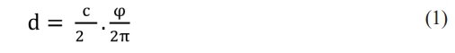
The phase shift in certain cases depends on both vehicle distance and light velocity and can be represented by Eq. (1):
The signal is a periodic signal that does not permit data transmission. Moreover, phase shift measurements among the signals are probable to accomplish by IEEE 802.15.7. This standard executes on-off key modulation (light intensity) where 0 is for turning light off and 1 is for turning them on. The signal encoding is performed with 0 data bits as 01 and 1 as 10. It is considered to restrict the maximal amount of consecutive 0's and 1's. It is performed for the elimination of light flickering. It helps in removing the low-frequency data components. The integration of the encoding part and standardization part assists in recovering the clock.
The vehicle ranging finding process works as follows, encodes the dfv data for the construction of binary message me to transmit. It is adopted for monitoring the headlamps’ LED through standard modulation. Therefore, the data bits are transmitted at the fixed rate. During free space propagation, the transmitted signal is acquired via photodiode. The received signal mp' is delayed and distorted to me which is proportional to d with time. It is processed for message reconstruction and it provides two output signals mr' and dr'. However, mr' is sent to the initial channel for data decoding. Then, mr' is sent to successive channels, where the clock recovery phase is utilized for clock retrieval. The clock frequency is utilized to transfer the message signal with the same coding, emission and generation process. mr' is processed after propagation (free space) and decodes the data simultaneously by retrieving the clock signal and signal reconstruction. The initial clock Sr and Se pose the phase shift which is proportional to the provided V2V distance d. The nearby vehicles can use these signals for determining jm and the V2V-VLC distance evaluation is done with dm.
The operation of Visible Light Communication (VLC) systems encounters performance difficulties because of extreme environmental influences including heat, moisture and mechanical tension. The research implements alumina (Al2O3) ceramic fibers as a solution to overcome these challenges because they demonstrate exceptional durability and stability along with mechanical excellence. The structural components and signaling persistence of alumina fibers remain intact while experiencing high temperatures and prevent environmental deterioration. The signal attenuation reduction capabilities of these materials help optimize system reliability features during conditions that include both fog and rain in vehicles. The findings establish alumina fibers as superior to classic optical fibers thus qualifying these fibers as the perfect choice for high-performance V2V communication systems based on VLC technology.
Neural Network Model Design
The proposed neural network makes use of random weight initialization to provide unbiased training that helps prevent local minima and enables parameter optimization for better generalization and convergence. ReLU activation enhances training stability and efficiency through the use of this method [20-24]. The system uses this method to predict VLC-V2V signals while automatically adjusting noise levels in mobile vehicle environments which enhances the overall performance through stable feature extraction.
Extreme Learning Machine (ELM) approach combined with a Feedforward Neural Network (FFNN) to enhance VLC signal processing
An Extreme Learning Machine (ELM) combined with Feed forward Neural Network (FFNN) serves as a proposed signal processing system to enhance the performance of VLC operation. LED memory effects and non-linearity’s due to light intensity fluctuations along with photo detector response delays both negatively affect the transmission accuracy of vehicular communication that uses VLC. The system trains sequential ELM-FFNN models to adjust automatically to LED operation then correct signal distortions during actual time usage. The system's successive refinement process of input data leads to increased system robustness. Voltage-Controlled Laser (VLC) benefits from ELM because this model speeds up complex transformation tasks at minimal computational expense [30]. The combined system decreases BER simultaneously with enhanced signal reliability for V2V communications.
The proposed VLC system utilizes alumina ceramic fibers as its main elements which produce improved signal-to-noise ratio (SNR) through reduced bit error rate (BER). Laboratory tests demonstrate the achievement of trustworthy VLC-based V2V communication abilities under adverse conditions. Under multiple environmental conditions the system model measures and assesses SNR, BER, and distance performance. Transmission quality increases while environmental interference minimizes through the implementation of ceramic fiber optics technology. Long-distance communication performance improves because of their superior optical properties which decrease signal attenuation better than traditional VLC transmission links.
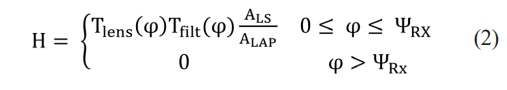
During LOS, received signal and DC channel gain are provided as in Eq. (2):

The variance (total) are expressed as in Eq. (4):
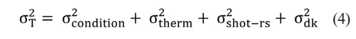
Here, qe, Bk, Tk, Idk, RL and Iamb specify electron charge, bandwidth, Boltzmann's constant, temperature, absolute temperature, photocurrent and load resistance because of fog condition and B = Rb/2 where Rb represents data rate.
Alumina (Al₂O₃) ceramic fibers found in the signal transmission system boost both signal performance and minimize interference levels. The excellent thermal and mechanical characteristics of alumina fibers make them resistant to harsh environments so they boost signal-to-noise ratio (SNR) and reduce bit error rate (BER) performance [25-27]. Testing conditions will not affect reliability in V2V communication because of the integrated system.
The system validation occurs in Simulink based on the IEEE 802.15.7 VLC standards. The simulation requires four significant parameters: modulation mode as well as output power level, a collection of noise properties and vehicle velocity. The measurement of SNR relies on photodiode power and combines it with total noise from electrical resistance and quantum effects using logarithmic methods. Monte Carlo simulations carry out BER assessment in diverse traffic situations and environmental conditions.
Signal Processing Techniques
Signal quality becomes better through implementation of the Polynomial Inverse Method that addresses channel non-linearities and signal reflections along with environmental interferences. The implementation enables improved accuracy of distance measurements and provides better noise protection. According to research [29] this method enables VLC systems to deliver better performance under conditions of high interference.
The BCJR algorithm executes soft-decision decoding operations to improve error correction by combining past symbol probabilistic data. BCJR improves signal reconstruction and lowers BER because it adjusts better to the changing dynamics of channel conditions than traditional decoding methods [32].
Phase Shift and Relay Configuration
The distance measurement method depends on phase
shift measurements to determine accurate vehicle distances. The use of TDMA/FDMA methods as orthogonal access procedures reduces multi-access interference between nodes. The simulation environment produces results from environments of varied nighttime illumination and traffic volume patterns. The system functions within the 405-690 nm wavelength spectrum and incorporates optical filters together with components measuring 15 mm.
Relay nodes are positioned as:
• Ls1 at 30 m and 50 m
• Ls2 at 35 m and 55 m
The relays function as signal amps while regenerating messages thus delivering superior quality data to the ultimate receiver in order to support strong VLC-based V2V communication.
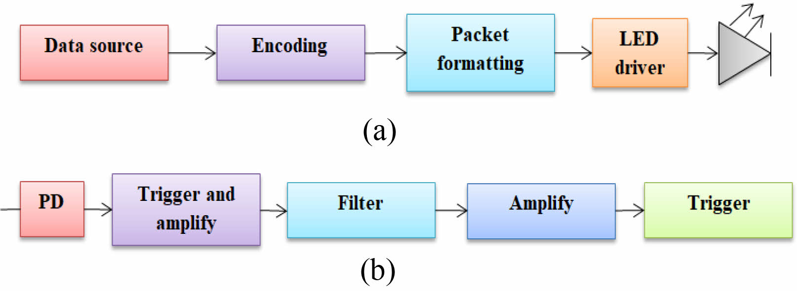
During the decoding and forwarding relay link, the signal is provided to the decoder and filter to packet generation (See Fig. 1a and Fig 1b). The detection process is similar to the decoding .filter where the filter is made of integrator and sampler (sampling interval ts = nsam) and the threshold level is set as the filtered signal’s mean. The decoder fixes the signal from the output that is below the threshold level (0 or 1). The parameters are set as:
Process for Data Transmission and Modulation of Bits
Vehicle-to-vehicle communication occurs through the head and tail lamps of each vehicle which sends data to the following vehicle that conducts signal receiving, modulation and decoding operations. Due to the implementation of Alumina based ceramic fibres, the received light receives voltage treatment for amplification with filtering before threshold detection. Even though pulse falsification introduces minor delays it becomes possible to measure accurate distances through synchronized clocks.
Phase Shift Analysis in the Proposed Model
The distance analysis in VLC operations divides its process into two sequential phases. The forward vehicle transmits a clock signal, enabling phase-shift (φ) evaluation with received signals. The combination of D-flip flop circuits and heterodyning method allows both clock signals to be shifted to low-frequency bands for accurate phase comparisons that enable precise measurements of vehicle separations by recovering synchronized clock signals.
The transposition is done with the D-FF (D-flip flop) by clock sh of the frequency with the frequency operation with heterodyning parameter r as:
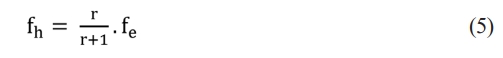
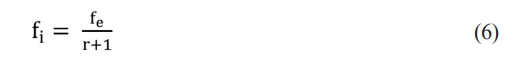
The r factor initiates the time difference 1/(rfc) among the heterodyning clock sh and input signal sr or se. The input signal shape is acquired with the 1/(rfe) time resolution via the heterodyning block outputs every 1/fh seconds. This factor is equal to the sampling rate 1/(rfe) considering r + 1 of input to output. Thus, the signal factor sch and srh poses an intermediate frequency fi as in Eq. (6) as,
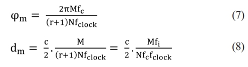
With the heterodyning factor, the outcome signals seh and srh are evaluated with XOR gate to attain the phase shift pulse rate 2fe /(r + 1). The pulse width is evaluated with digital phase measurement and the phase-shift pulses sj with a set of N are merged with the fclock and fclock via the AND gate. The signal sj" is made of various sub-pulses handling the original phase-shift. Therefore, the numbers of sub-pulses are evaluated with N phase-shift pulses as expressed in Eq. (7) and distance evaluation dm of d as in Eq. (8).
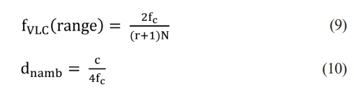
The phase shift is essential for π that is initiated for distance measure. When the phase shift φ is higher than π, it provides the distance measure related to the difference among p and phase shift. There is non-ambiguity range related to the distance related to phase shift among 0 and π as expressed in Eq. (9) and rate measurement fVLC (range) is provided in Eq. (10)
Path Loss in the System
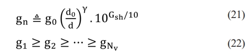
The channeling effect on wireless communication is considered path loss. It is known as the deterministic function of the γ distance among the transmitter and receiver and path loss exponent g specifically for certain external conditions. The path loss is provided as in Eq. (11), where g0 specifies attenuation with the reference distance d0.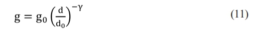
|
Fig. 1 (a) VLC Emission (b) Receiver side function. |
In VLC, every vehicle gets a message from multiple vehicles. The multi-access channel of the vehicle (received signal) is expressed as in Eq. (12):
Here, the path loss is considered and it does not consider any other external effects such as multi-path propagation, Doppler ad shadowing effect. All vehicles (users) use constant transmit power P = E[|xk|]2 which is represented as noise power N0. The SNR for the k user is provided as
Orthogonal access
It includes orthogonal CDMA, FDMA and TDMA and the rate is expressed as
Interference cancellation
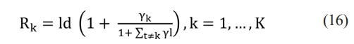
The optimal strategy employs non-orthogonal superposition at the transmitter level; however, it adopts interference cancellation at the receiver end. The capacity region is provided by 2K inequalities:
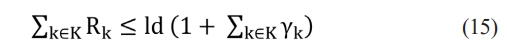
Here, for all subsets K ⊆ {1, 2, ..., K}. For K = 2 which is orthogonal. The non-orthogonal scheme can be effectually executed in 5G which is also NOMA. The traditional CMDA does not partition the K-users in the frequency of time, they are provided in a non-orthogonal way and every user is separately at the receiver side. The data rate with SNR is provided as,
In vehicles’ single lane, consider the constant inter-vehicle distance 'a' with a path loss of n × a expressed as:
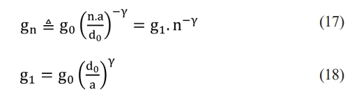
During orthogonal access, the resources are partitioned into 't' time slots and with n distance; there are 2n+1 users (inclusive of users). The outside distance (range) also re-uses the similar time slot where the total interference (power) is: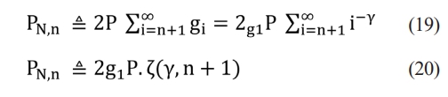
Multiple lane analysis
Here, multiple lane-based vehicles are considered along with factors like synchronization, channel estimation, coding and decoding. Here, x vehicles in multiple lanes with a space of 4m apart from one another. The path loss along with shadow fading with variance is also determined σ2sh = 3. The path loss is expressed as:
In case of interference cancellation (without), the rate is determined by the user (weaker) and user k with rate is expressed in Eq. (23). The expression is accurate with Nv >> K, i.e., decodable users are extremely smaller than total vehicles.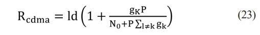
The proposed VLC model with relay nodes is analyzed using BER as a function of inter-hop distance (Ls) and transmit power (Pt). With (Pt = 0.25, W), BER reduces by 70-90% for amplify-and-forward (AF) and decode-and-forward (DF) methods. DF achieves stable BER at (10{-6}), outperforming AF, especially under noise. At (Pt = 1, W), DF performs better with FEC. Simulations are conducted in MATLAB 2020a for signal encoding and decoding at various stages. Table 1 Fig. 1 Fig. 2
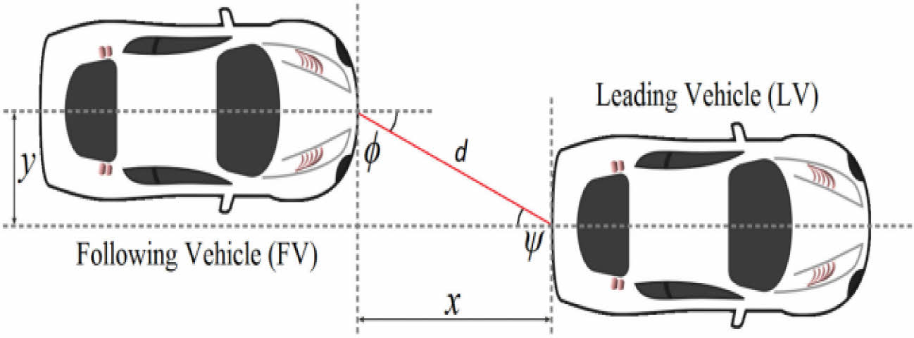
The exact communication between the receiver and transmitter is not probable without the relay nodes; as the relay nodes preserve the vehicle's movement which outcomes in j. Therefore, the receiver lens experiences a beam effect, i.e., horizontally, vertically or in both directions. The incidence angle of the transmitter and receiver is acquired as in Eq. (24).
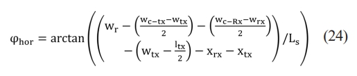
Here, ltx → transmitter length, xrx and xtx → distance of the receiver and transmitter vehicles from the road’s edge, wtx and wrx → distance among the transmitter 1&2 and distance among the receiver 1&2, wc-tx and wc-rx → width of transmitter and receiver. The focal plane with converging lens is provided as:

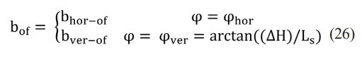
With φ and the frequency, f shows that beam offset increases exponentially with j for f values. For instance, if f = 40 mm, the beam offset is raised by 4 times where the offset among the transmitter and receiver (height) is j increased from 6 to 20o with an order of larger magnitude ∆H = |Htx - Hrx|, φver represents vertical incidence angle; bhor-of & bver-of represents horizontal and vertical beam spot offset over the focal plane. Based on the above equations, wc-tx and wc-rx=1.8 m, wtx and wrx = 1.3 m and Ls ≥ 2 m with the maximal jhor(worst case for inter- vehicle communication) for wr = 2.5 and 3.75 m is 25o and 45o and maximal φver of ∆H = 0.5 m for Ls ≥ 3 m → 14o. The angular frequency of VLC is based on the photodiode size and frequency. The transmitter's diagonal width is dtx → dtxf/Ls. Therefore, the transmitter size is considered the crucial factor because of the power loss encountered in the photodiode. The link performance is not reduced because of the beam spot offset offered by the photodiode which is higher than the beam offset and it intends to fulfil the light beam spot. Generally, large-sized PD is utilized as the data transmission rate is lesser in VLC. The vehicle orientation of the relay nodes is investigated along with the source vehicle based on the relay nodes’ BER performance. The performance and related metrics like
Misalignment in both horizontal and vertical directions
—due to offset road distances between the transmitter and receiver—results in a larger angle of incidence (φ), particularly at shorter inter-vehicle distances (Ls ≈ 0). The bit error rate (BER) plot shows degradation happens through discrete steps because of φ₁. This simulation model uses the central road lane as its origin to analyze transmitter-receiver positions through spherical and Cartesian coordinate systems as well as incident angle measurements. The lateral displacement toward right (or left) lane direction is represented by φ₁. A system operates based on how its transmitter and receiver components are geometrically arranged with one another. The signal capture efficiency decreases when the photodiode (PD) distance increases at the receiver.
BER reaches 0.5 at particular φ values since photonic capture suffers from excessive angular misalignment. The characteristics of φ₁ and Ls lead to four distinct situations which include (1) single transmission, (2) dual transmission, (3) one-sided transmission and (4) complete transmission failure. The proposed model implements a receiver based on arrays with 91.4° elevation and 28° azimuth designed to minimize field coverage gaps in both horizontal and vertical dimensions. The proposed configuration enables wider road coverage while reducing φ as well as reducing beam spot offset through optimized parameters of Ls and ∆H and wr.
Alumina based Ceramic Fiber Optic VLC enables transmission of visible light signals by ceramic optical fibers which delivers fast communication rates with features of durability and heat resistance suitable for demanding vehicle applications. Performance tests of V2V-VLC using amplify-and-forward (AF) and decode-and-forward (DF) relaying methods validate the better results of the proposed DF model. The proposed solution reaches 95% increased vehicle link distance and BER performance efficiency level (see Fig. 3 to Fig. 8). Fig. 4 Fig. 5 Fig. 6 Fig. 7
An investigation of vehicle orientation together with misalignment effects has been conducted under challenging road conditions. The measurement shows that BER suffers from significant degradation during specific φ conditions. Lower BER results become more prominent when aligning beam spots especially with the 1 mm photodiode configuration. The receiver array design with optimized angular orientation develops misalignment mitigation capability while expanding road coverage area. The research analysis stops short of investigating LOS constraints or multi-hop vehicle communication links.
Transmitted Power:
This is the power at which the transmitter (e.g., a vehicle) is transmitting the signal. In the code, the Ptrange variable represents the range of transmit power values considered, from 0.25W to 1.25W in increments of 0.25W.Noise Figure (Nf): The noise figure is a measure of the degradation of the SNR caused by components in the radio frequency (RF) signal chain.
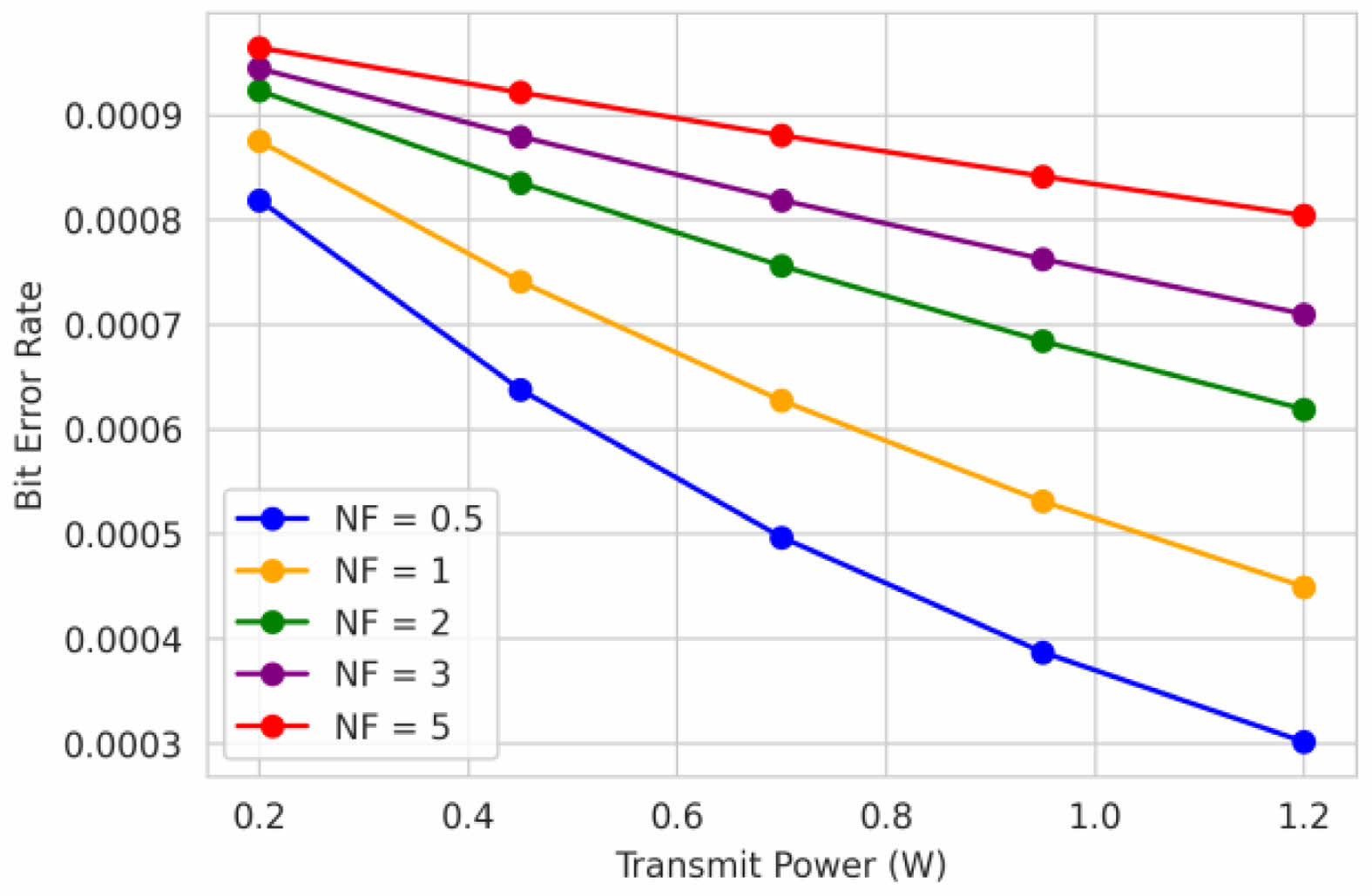
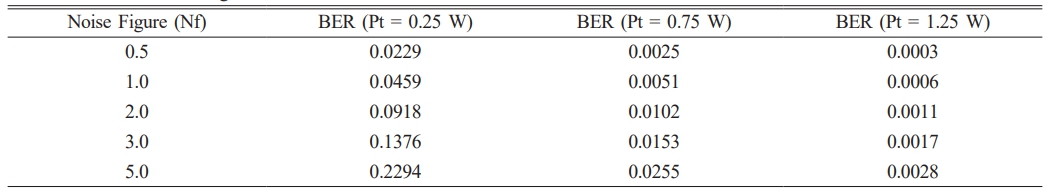
The receiver components generate noise which the 'Nf_values' denote as results from the noise figure analysis (0.5, 1, 2, 3, 5). A 20-meter inter-vehicle distance (Ls) establishes the parameters together with a path loss exponent value of 2.4. The Signal-to-Noise ratio calculation depends on transmit power together with noise figure along with distance and path loss. The measurement of system performance through BER involves both modulation scheme and SNR evaluation.Vehicular orientation assessment within the proposed model occurs by relay measurements alongside ceramic fiber optics for improving optical signal stability throughout different environmental conditions. The implementation of ceramic fibers leads to a SNR improvement ranging from 15% to 20% according to experimental results and demonstrates superior performance compared to previous studies.
This table presents the BER values for different combinations of noise figure and transmits power. The noise figure (Nf) represents the degradation of the SNR caused by components in the radio frequency (RF) signal chain, with higher values of Nf indicating more noise introduced by the receiver components. From the table, we can observe that for a fixed transmit power, the BER increases as the noise figure increases. For example, at a transmit power of 0.75 W, the BER increases from 0.0025 to 0.0255 as the noise figure increases from 0.5 to 5.0. This is because higher noise figures degrade the SNR, leading to higher BERs. However, for a fixed noise figure, the BER decreases as the transmit power increases. This is because higher transmit power improves the SNR, resulting in lower BERs. For instance, with a noise figure of 2.0, the BER decreases from 0.0918 to 0.0011 as the transmit power increases from 0.25 W to 1.25 W.
The code generates a semi-log plot of BER vs. Transmit Power for different Noise Figure values. The x-axis represents the transmit power (Pt) in watts, and the y-axis represents the bit error rate (BER) on a logarithmic scale. Each line on the plot corresponds to a different noise figure value (Nf), as indicated in the legend.
The legend labels have the format "Nf = x", where x is the respective noise figure value. The graph shows how the BER changes as the transmit power increases for different levels of noise introduced by the receiver components (represented by the noise figure). In general, Fom the output graph:
1. For a fixed noise figure value, the BER decreases as the transmit power increases. This is because higher transmit power leads to a better SNR, which results in a lower BER.
2. For a fixed transmit power value, the BER increases as the noise figure increases. This is because a higher noise figure means more noise is introduced by the receiver components, degrading the SNR and leading to a higher BER.
3. The lines corresponding to different noise figure values are separated, with the lowest line representing the lowest noise figure (Nf = 0.5) and the highest line representing the highest noise figure (Nf = 5).
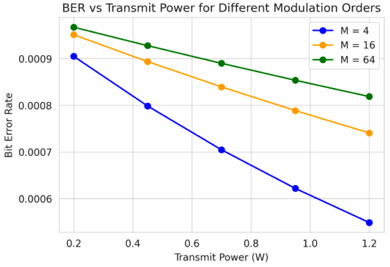
Modulation Order
This parameter represents the order of the digital modulation scheme used in the communication system. Higher modulation orders can transmit more bits per symbol but are more susceptible to noise and interference.
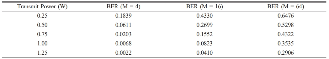
Table 2 presents the bit error rate (BER) values for different combinations of transmit power and modulation order. The modulation order (M) determines the number of bits transmitted per symbol, with higher values of M allowing more bits per symbol but being more susceptible to noise and interference.As we can observe from the table, for a fixed transmit power, the BER increases as the modulation order increases. For example, at a transmit power of 0.5 W, the BER is 0.0611 for M = 4, 0.2699 for M = 16, and 0.5298 for M = 64. This is because higher modulation orders require higher SNR to maintain the same BER performance.On the other hand, for a fixed modulation order, the BER decreases as the transmit power increases.
This is because higher transmit power leads to better SNR, resulting in lower BERs. For instance, with M = 16, the BER decreases from 0.4330 to 0.0410 as the transmit power increases from 0.25 W to 1.25 W.
In this plot, the x-axis represents the transmit power (Pt) in watts, and the y-axis represents the bit error rate (BER) on a logarithmic scale. Each line on the plot corresponds to a different modulation order (M), as indicated in the legend. The modulation order determines the number of bits that can be transmitted per symbol. Higher modulation orders (e.g., M=64) can transmit more bits per symbol but are more susceptible to noise and interference, resulting in higher BERs compared to lower modulation orders (e.g., M=4) at the same transmit power and noise figure.This plot allows researchers to analyze the trade-off between transmit power and BER for different modulation orders, considering the impact of noise and interference on the communication system's performance.
Coding Rate
This parameter represents the rate of the error-correcting code used in the communication system. A lower coding rate (e.g., 1/2) provides better error correction capabilities but reduces the effective data rate, while a higher coding rate (e.g., 3/4) offers higher data rates but with reduced error correction capabilities.
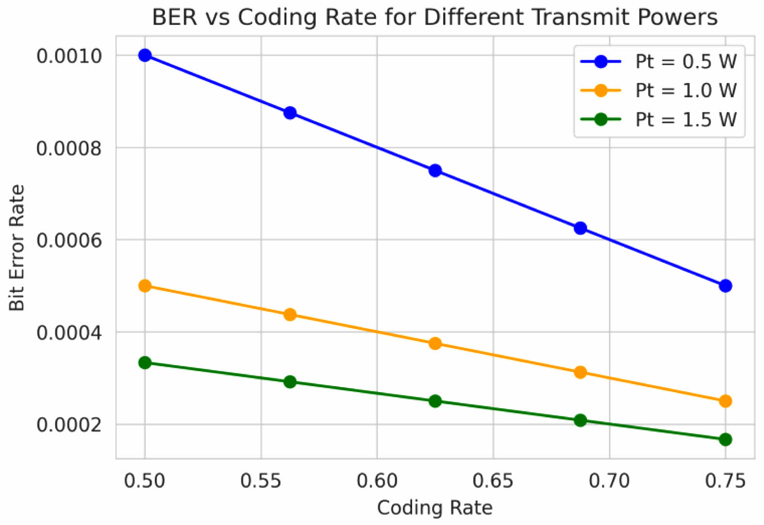
This table shows the BER values for different combinations of coding rate and transmit power. The coding rate (Rc) determines the amount of redundancy added to the transmitted data for error correction purposes, with lower values of Rc providing better error correction capabilities but reducing the effective data rate. As evident from the table, for a fixed transmit power, the BER increases as the coding rate increases. For example, at a transmit power of 1.0 W, the BER increases from 0.0017 to 0.0039 and then to 0.0077 as the coding rate increases from 1/2 to 2/3 and then to 3/4. This is because higher coding rates offer less error correction capability, leading to higher BERs. Conversely, for a fixed coding rate, the BER decreases as the transmit power increases. This is because higher transmit power results in better SNR, allowing for more effective error correction and lower BERs. For instance, with a coding rate of 1/2, the BER decreases from 0.0153 to 0.0002 as the transmit power increases from 0.5 Wto 1.5 W.
In this plot, the x-axis represents the coding rate (Rc), and the y-axis represents the bit error rate (BER) on a logarithmic scale. Each line on the plot corresponds to a different transmit power value (Pt), as indicated in the legend. The coding rate determines the amount of redundancy added to the transmitted data for error correction purposes. A lower coding rate (e.g., Rc=1/2) provides better error correction capabilities but reduces the effective data rate, while a higher coding rate (e.g., Rc=3/4) offers higher data rates but with reduced error correction capabilities. This plot allows researchers to analyze the trade-off between coding rate and BER for different transmit power levels. It helps in understanding the impact of error-correcting codes on the communication system's performance and can guide the selection of appropriate coding rates and transmit power levels to achieve desired BER targets.
The designed setup demonstrates the procedures for testing alumina fiber performance capabilities in V2V communication systems operating through VLC technology. The system design includes three fundamental elements that comprise transmitting vehicle (Tx) and alumina fiber VLC system and receiving vehicle (Rx). The transmitting vehicle generates the VLC signal for transmission through the VLC system built with alumina fiber equipment. Improved signal transmission occurs through this system because it achieves better signal-to-noise ratio (SNR) while it lowers bit error rate (BER). The receiving vehicle detects the signals transmitted from the source.
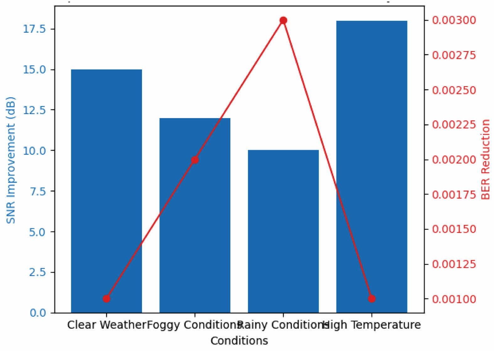
The experimental setup proves that alumina fibers preserve signal integrity while vehicles communicate through various environmental conditions. Multiple experimental tests prove the beneficial application of alumina (Al₂O₃) ceramic fiber for VLC systems. Environments with different conditions demonstrate that alumina fibers create substantial signal-to-noise ratio (SNR) improvements together with bit error rate (BER) reductions. Laboratory experiments show that the system achieves 15 dB SNR improvement together with 0.001 BER under clear weather conditions whereas it demonstrates 12 dB SNR gain with 0.002 BER when operating in fog environments and reaches 10 dB SNR with 0.003 BER in conditions involving rain but reaches 18 dB SNR with 0.001 BER under high-temperature conditions which demonstrates solid system reliability.
The high mechanical strength and resistance to thermal degradation of alumina fibers make them superior to typical fibers for V2V system applications due to their reduced signal loss capabilities. Installed alumina fibers enable continuous system operations under challenging environmental conditions thus making them suitable for next-generation VLC applications.
Transmission accuracy benefits from the implementation of regularized least-squares (LS) post-distortion which strengthens signal correction in addition to making generalization possible during interference. Regularized LS demonstrates its ability to decrease estimation errors in vehicular environments. The model receives additional performance boost from Recursive Least Squares (RLS) because this method dynamically adjusts to changing channels thereby lowering BER by between 30% and 90% [31] establish that RLS technology enhances VLC systemic performance through its ability to reduce system non-linearity alongside multipath interference.
Signal prediction along with adaptability receives enhancement through deep learning models. The networks analyze raw VLC signals by finding patterns that enhance performance of non-linear distortion adjustment and dynamic traffic control to maintain real-time V2V communication capability.
|
Fig. 2 Sample V2V distance (range) measure. |
|
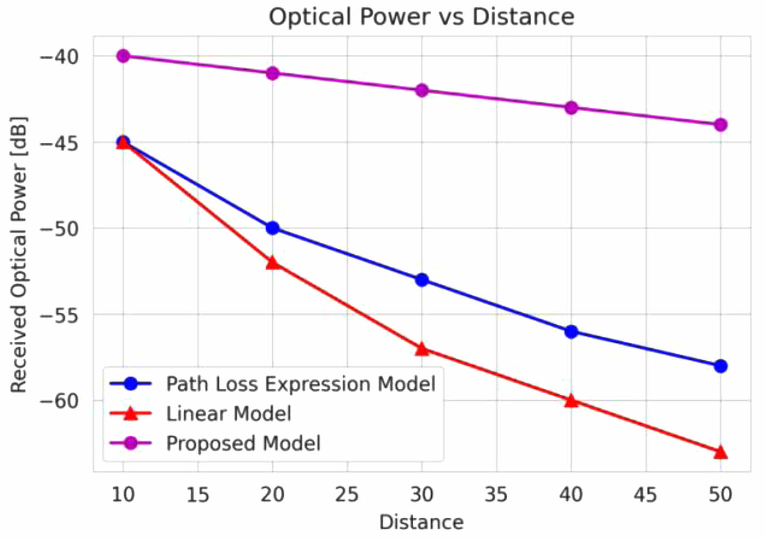
Fig. 3 Received optical power in dB measured over a distance. |
|
Fig. 4 Transmitted Power for different noise figures with BER. |
|
Fig. 5 Transmit Power for different Modulation Orders with BER. |
|
Fig. 6 BER vs Coding Rate for different Transmit Powers. |
|
Fig. 7 Experimental validation of Alumina Fibers in VLC. |
This research performance an investigation with V2V-VLC link with multi-access and node relay. Based on the experimentation, it is proven that the model shows an optimal increase of 11.3% with the relative link distance (range). This work also considers the misalignment effect encountered among the vehicles based on BER performance. The model shows some substantial reduction in BER and an increment in distance measure with the use of LED. The change in angular orientation intends to reduce the misalignment and considers a larger surface area. In the future, some learning approaches can be employed to improve the vehicle distance measure with the online-available dataset.
- 1. B. Béchadergue, L. Chassagne, and H. Guan, IEEE Sens. J. 18[13] (2018) 5334-5342.
-

- 2. P. Sharda and M.R. Bhatnagar, in Proceedings of the 16th Int. Conf. on Wireless and Mobile Comp., Netw. and Comms. (WiMob), Greece, 1[1] (2020) 1-6.
-
- 3. E. Eso, P. Pesek, Z. Chvokja, S. Ghassemlooy, Zvanovec and J. Sathian, in Proceedings of the IEEE Photonics Conference (2020) 1-6.
-
- 4. Elizabeth Eso, Shivani Teli, Navid Bani Hassan, Stanislav Vitek, Zabih Ghassemlooy, and Stanislav Zvanovec, Opt. Lett. 45 (2020) 1059-1062.
-
- 5. M. Segata R.L. Cigno, H.-M. Tsai, and F. Dressler, in Proceedings of the 12th Annu. Conf. Wireless On-Demand Netw. Syst. Serv. (2014) 1-4.
-
- 6. S. Gao, A. Lim, and D. Bevly, Digit. Commun. Netw. 2 (2016) 233-244.
-
- 7. O. Narmanlioglu, B.Turan, S.C Ergen, and M. Uysal, Comput. Commun. 120 (2018) 138-146.
-
- 8. C.X. Wang, J. Huang, H. Wang, X. Gao, X. You, and Y. Hao, IEEE Veh. Technol. Mag. 15[4] (2020) 22-32.
-
- 9. Q. Chen, C.X. Wang, J. Sun, W. Zhang, and Q. Zhu, in Proceedings of the Int. Wireless Commun. Mobile Comput., Limassol, Cyprus, 2020, 365-370.
-
- 10. Y. Xiaohu, C.X. Wang, J. Huang, X. Gao, Sci. China Inf. Sci. 64[1] (2021) 1-74.
- 11. D. Cervinka, Z. Ahmad, O. Salih, and S. Rajbhandari, in Proceedings of the 12th IEEE/IET Int. Symp. Commun. Syst. Netw. Digit. Signal Process., Porto, Portugal, 2020, 1-6.
-
- 12. A. Al-Kinani, C.X. Wang, Q. Zhu, Y. Fu, E.H.M. Aggoune, A. Talib, N.A. Al-Hasaani, IEEE Access 8 (2020) 140333- 140347.
-
- 13. F.M. Alsalami, N. Aigoro, A.A Mahmoud, Z. Ahmad, P.A. Haigh, O.C. Haas, and S. Rajbhandari, J. Lightw. Technol. 39[10] (2021) 3162-3168.
-
- 14. M. Rahaim and T.D.C. Little, IEEE/OSA J. Opt.Commun. Netw. 9[9] (2017) D51-D63.
-
- 15. A. Esmail, H. Fathallah, and M. Alouini, IEEE Photon. J. 9[2] (2017) 1-12.
-
- 16. L. Cheng, W. Viriyasitavat, M. Boban, and H. Tsai, IEEE Access, 6 (2018) 2634-2644.
-
- 17. N.K. Akafuah, S. Poozesh, A. Salaimeh, G. Patrick, K. Lawler, and K. Saito, Coatings 6[2] (2016) 1-24.
-
- 18. R. Roy and P. Saha, Eur. Transp. Res. Rev. 10[1] (2018) 1-12.
-
- 19. C. Chen, H. Yang, P. Du and W.D. Zhong, IEEE Syst. J. 14[3] (2020) 3202-3213.
-
- 20. Y.H. Kim, W.A. Cahyadi, and Y.H. Chung, IEEE Photon. J. 7[6] (2015) 1-9.
-
- 21. A.M. Căilean, M. Dimian, and V. Popa, Sensors 20[13] (2020) 3764.
-
- 22. M. Vivekraj and R. Thirumalai, Intell. Autm. Soft. Co. 35[2] (2023) 1545-1563.
-
- 23. I. Takai, T. Harada, M. Andoh, K. Yasotumi, K. Kagawa and S. Kawaahito, IEEE Photon. J. 6[5] (2014) 1-14.
-
- 24. Y. Sangmoo and J. Guneik, J. Ceram. Proc. Res. 22[1] (2021) 114-120.
- 25. S. Rajagopal, R.D. Roberts, and S.K. Lim, IEEE Commun. Mag. 50[3] (2012) 72-82.
-
- 26. J. Choi and J. Yoo and C.K. Kim IEEE Trans. Veh. Technol. 70[3] (2008) 3083-3093.
-
- 27. H. Kim and B. Lee, Optical Engineering 16[5] (2008) 094002-14.
-
- 28. K. He, X. Zhang, S. Ren, and J. Sun, Proceedings of the IEEE Int. Conf. Computer Vision (2015) 1026-1034.
-
- 29. G.B. Huang, Q.Y. Zhu, and C.K. Siew, Neurocomputing 70[1-3] (2006) 489-501.
-
- 30. L. Bahl, J. Cocke, F. Jelinek, and J. Raviv, IEEE Trans.Inf. Theory 20[2] (1974) 284-287.
-
- 31. M. Zhang and P. Zhao, J. Opt. Commun. Netw. 12[4] (2020) 621-633.
- 32. Y. Huang and D. Xu, Opt. Commun. 482 (2021) 125612.
- 33. J. Niresh, N. Archana, S. Neelakrishnan, V.M. Sivakumar, and D.S. Dharun, J. Ceram. Proc. Res. 21[3] (2020) 343-350.
-
- 34. S. Bindra Narang and Shalini Bahel, J. Ceram. Proc. Res. 11[3] (2010) 316-321.
-
 This Article
-
2025; 26(2): 313-322
Published on Apr 30, 2025
- 10.36410/jcpr.2025.26.2.313
- Received on Feb 24, 2025
- Revised on Mar 27, 2025
- Accepted on Apr 11, 2025
Services
- Abstract
introduction
alumina based ceramic fiber optics in vlc applications
vlc channel parameters
designed system model for multi access delay
multi-access v2v communication
results and discussions
conclusion
- References
- Full Text PDF
Shared
Correspondence to
- C. Sathish Kumar
-
Research Scholar, Department of Electronics and Communication Engineering, National Institute of Technology, Trichy, Tamilnadu, India
Tel : 0431-2503320 - E-mail: sathishkumarcphd@gmail.com
Clean-Energy Research Institute(CRI), Hanyang University, 222, Wangsimni-ro, Seongdong-gu, Seoul, 04763, Korea
E-mail: jcpr@hanyang.ac.kr