


- Experimental investigations of composite column with and without fibre
M. Surendara, S. Lavanya Prabhab, G. Prabhac,* and M. Sivad
bProfessor, Easwari Engineering College, Chennai, Tamil Nadu, India
a,c,dAssistant Professor, Easwari Engineering College, Chennai, Tamil Nadu, IndiaThis article is an open access article distributed under the terms of the Creative Commons Attribution Non-Commercial License (http://creativecommons.org/licenses/by-nc/4.0) which permits unrestricted non-commercial use, distribution, and reproduction in any medium, provided the original work is properly cited.
Concrete-filled steel tube (CFST) columns offer notable advantages over traditional reinforced concrete columns, including improved energy dissipation, strength, and stiffness. This research explores the structural behavior of CFST stub columns under uniaxial compression, focusing on the impact of steel fibers in M30 grade concrete. Nine CFST specimens with different slenderness ratios were tested to examine their axial load behavior. The study evaluates variables such as ultimate load capacity, axial load-deformation response, strain characteristics, failure modes, concrete confinement, and axial strength. Tests included hollow and concrete-filled steel tubes (100 mm inner diameter, 3mm thick) at heights of 200 mm, 300 mm, and 400 mm, with slenderness ratios of 1.89, 2.83, and 3.77. Three specimens per ratio (hollow, concrete-filled, and fiber-reinforced) were tested. Vertical deformation, vertical strain, and lateral strain were measured. Confinement factors were 0.708 for plain concrete and 0.574 for fiber-reinforced concrete. Results showed an 8.34% increase in ultimate load capacity for fiber-reinforced concrete at a 3.77 ratio, while other ratios had marginal gains. Fiber reinforcement improved stiffness by 20.48%, 6.25%, and 0.56% for the respective heights, with ultimate load capacities increasing by 0.96%, 2.46%, and 8.34%. Vertical shortening varied, and strength indices decreased with height.
Keywords: Concrete-filled steel tube (CFST), Steel fiber reinforced concrete (SFRC), Load-bearing capacity, Stiffness, Strength enhancement index (SI), Load capacity, Ductility, Poisons ratio.
Concrete-filled steel tube (CFST) is a highly efficient composite structure that involves filling a steel tube with concrete. This combination offers rapid construction and excellent economic efficiency. The steel tube provides lateral confinement for the core concrete, while the core concrete limits the inward local buckling of the steel tube. This synergistic approach leverages the strengths of both materials, significantly enhancing the bearing capacity, ductility and stiffness of the structure. As a result, CFSTs are widely used in high-rise buildings, bridges, and large-span structures.
Concrete-filled steel tubular (CFST) columns are increasingly used in high-rise buildings due to their superior load-bearing capacity and fire resistance compared to traditional steel or concrete columns. CFSTs enhance material performance in composite action. Studies on concrete columns confined with fiber-reinforced polymer (FRP) tubes show that FRP confinement significantly improves strength, ductility, and energy absorption [3, 15, 30].
Experimental work on short steel tube columns filled with plain and steel fiber-reinforced concrete under axial load involved 36 specimens. Variables included steel fiber volume (0%, 0.6%, 0.9%, 1.2%), steel tube thickness (3, 4, 5 mm), and concrete strength (50-70 MPa). Failure modes, ultimate loads, and axial load-shortening relationships were analyzed [4, 8, 17, 31].
Research on square high-strength steel fiber-reinforced concrete (SFRC) filled steel tube columns under axial load tested 13 specimens, examining D/t ratio and bond strength effects [5, 6, 23, 32]. Results were compared to Eurocode 4, ACI, AS, and AISC standards. Another study investigated the behavior of plain and fiber-reinforced concrete filled slender steel tubular columns under eccentric compression, measuring strength, load-strain, load-deflection relationships, and failure modes [6, 16].
Studies on self-compacting CFST stub columns strengthened with carbon fiber-reinforced polymer (CFRP) laminates found transverse CFRP tubes optimal for circular columns and longitudinal CFRP tubes for square columns. The ultimate load increases with varying the column type [7, 8, 28]. A total of 114 specimens tested fiber-reinforced concrete (FRC) with low and normal strength as infill in CFST columns [8, 9, 10]. Enhanced flexural and tensile strengths of FRC improved strain gradient handling, column strength, stiffness, ductility, and energy dissipation [11, 12, 14].
In this study the CFST column are cast using M30 grade concrete and behavior of columns is analyzed against plain concrete and fibre reinforced concrete columns.
Hollow Steel Tube (HT) columns offer a high strength-to-weight ratio, easily fabricated and cost-effective, they are economical. HTFC columns enhance load-bearing capacity and fire resistance, crucial for heavy-duty applications and seismic zones. The concrete core prevents steel tube buckling, boosting stability in HTFC. HTFRC columns, with fiber reinforcement, improve strength, toughness, and crack control, enhancing longevity and durability. These columns resist impact and dynamic loads, suitable for high-impact areas. The combination of steel, concrete, and fibers allows for flexible, innovative architectural and structural solutions
The mild steel circular tubes were utilized to construct the steel frameworks for all samples. The steel tube's yield strength (fy) and elastic modulus (Es) were determined through coupon tests, resulting in average values of 304 MPa and 205 GPa, respectively. The construction materials included 53-grade Ordinary Portland Cement with a normal consistency of 30% and a specific gravity of 3.05. M30 grade concrete with and without steel Fibers, were investigated in this study and analyzed against the behavior of concrete filled with plain concrete. 30mm hooked steel fibres with 1000 MPa tensile strength are used with aspect ratio of 0.02 for making steel fibre reinforced concrete.
Specimen Preparation
The mix design M30 grade was carried as per IS: 10262 (2019) to suit severe exposure conditions. The developed concrete had a slump of 100 mm. For Steel Fiber-Reinforced Concrete (SFRC) 1% volume of steel fiber was used to make concrete.
For compressive strength evaluation, cubic specimens measuring 100×100×100 mm were cast. To determine split tensile strength 100 mm diameter cylindrical specimens were cast. Stress-strain behavior were studied using cylindrical specimens of 150 mm diameter and 300 mm height. Flexural strength testing was conducted using prismatic specimens sized 100×100×500 mm.
Twenty-seven test specimens, including 9 hollow steel tube (HT) specimens, 9 specimens with concrete filled steel tube (HTFC) and remaining 9 with steel fibre reinforced concrete filled steel tube (HTFRC) specimens, were tested under axial load. The tested parameters were type of concrete (plain concrete and FRC) and height of steel tube (200 mm, 300 mm and 400 mm). All specimens, steel tube had a thickness (t) of 3 mm and inner diameter of 100 mm. The height to diameter ratios is 1.89, 2.83 and 3.772 were studied in this paper.
Mechanical properties of concrete
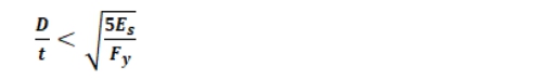
Concrete specimens were tested to evaluate the mechanical properties of control concrete and fibre reinforced (FRC) concrete mixtures in a 1000 kN capacity Universal Testing Machine conforming to IS: 516:1959. The test arrangements for the specimens are shown in Fig. 1. Three identical specimens of size 100 mm cubes were tested at the curing age of 3, 7 and 28 days under compression. Mechanical properties, viz., compressive strength, split tensile strength and flexural strength of conventional concrete and fibre reinforced concrete are presented in Table 1. The percentage increase in cube compressive strength, cylinder compressive strength, split tensile strength and flexural strength in FRC are 23.40%, 43.42%, 43.79% and 61.49%, respectively, when compared to conventional concrete specimens.
Behavior of Hollow and Concrete Filled Steel Tube Columns
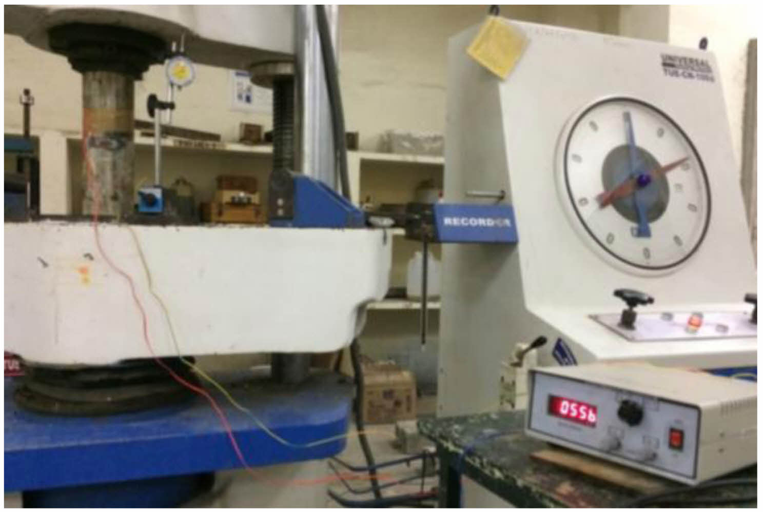
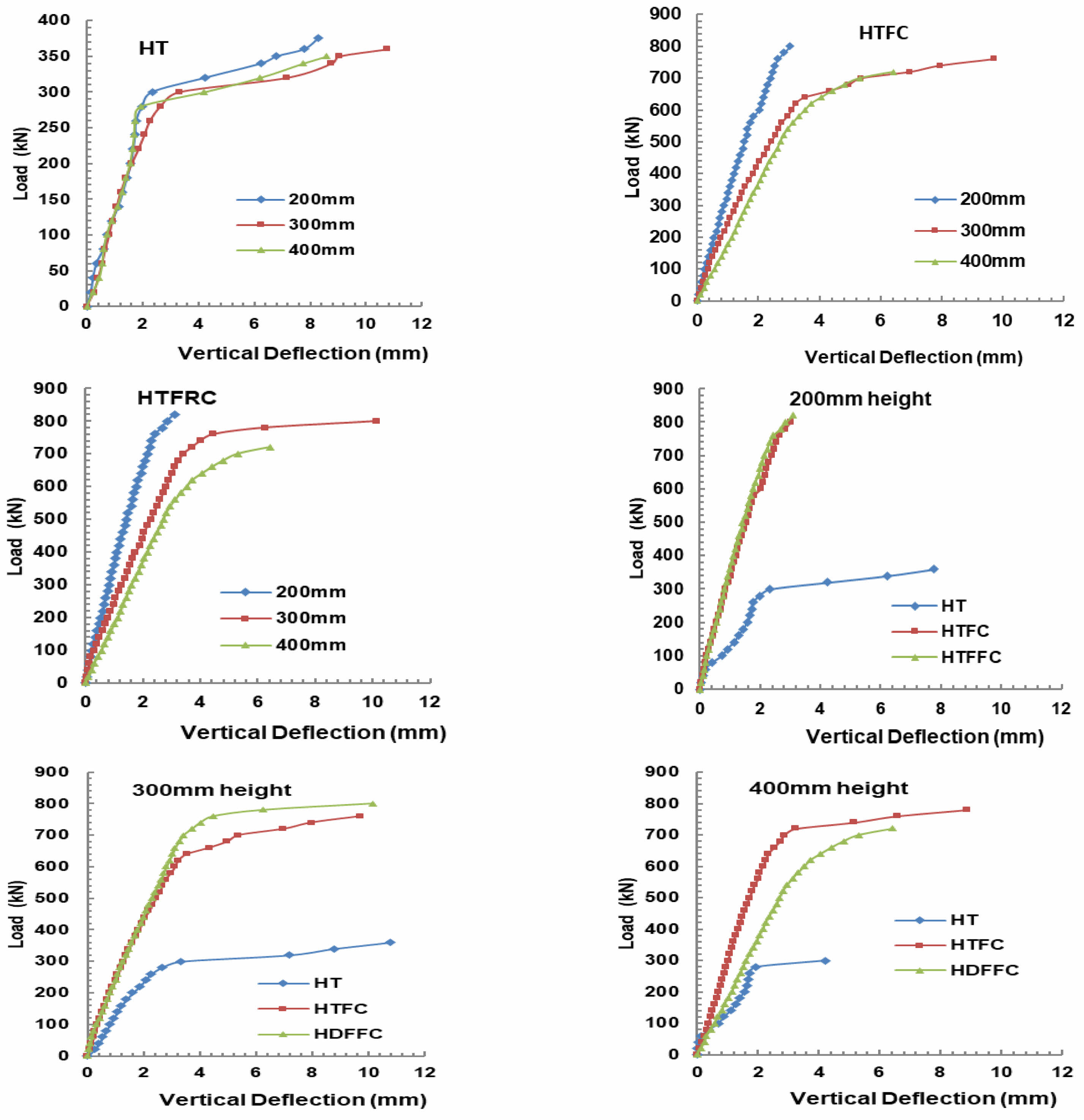
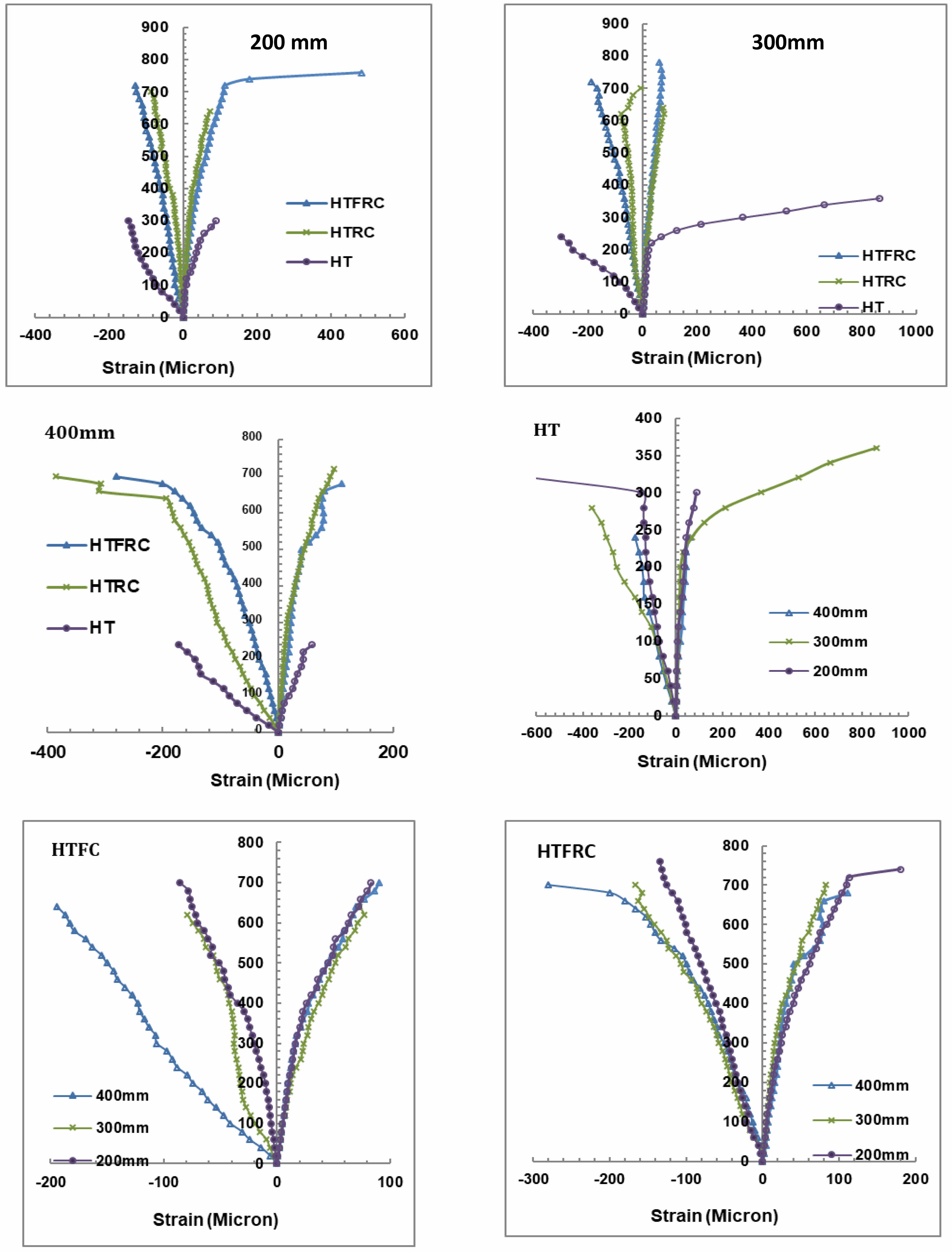
Hollow steel tube columns (HT), Hollow steel tube filled with concrete columns (HTFC) and hollow steel tube filled with fibre reinforced concrete (HTFRC) of 200 mm, 300 mm and 400 mm height were tested under universal testing machine of capacity 1000 kN. Vertical shortening and vertical and horizontal strain values were observed at different load intervals by using dial gauge and electrical strain gauges. Table 2 presents the geometric properties of column specimens. Load-vertical shortening of 400 mm, 300 mm and 200 high columns of HT, HTFC and HTFRC and also HT, HTFC and HTFRC columns at different heights are shown in Fig. 2.
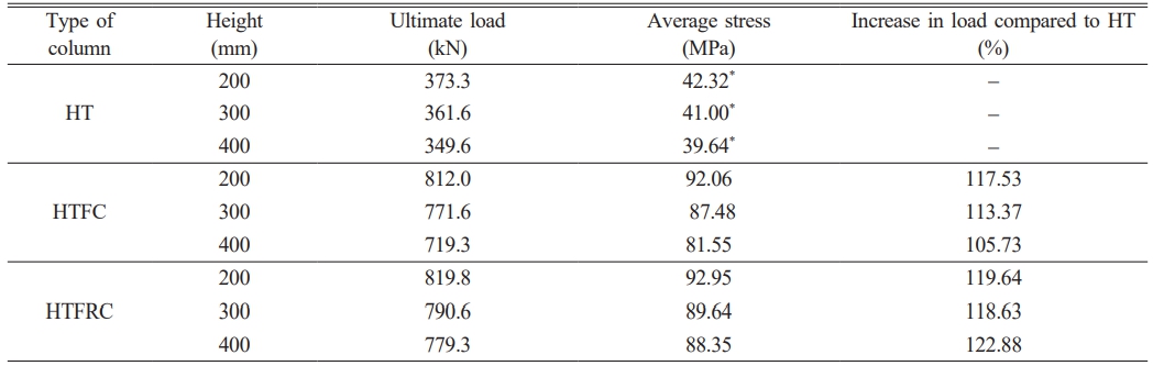
Table 3 displays the ultimate load carrying capacity of columns tested under uniaxial compression. The results indicate that the ultimate load carrying capacity decreases with increasing column height for all types of columns. Compared to HTFC columns, HTFRC columns demonstrated an increase in ultimate load capacity across all specimen heights.
Table 4 presents parameters for concrete and FRC-filled specimens, along with the ultimate load-carrying capacity and stiffness of all columns tested under uniaxial compression. The data shows that as column height increases, both stiffness and ultimate load-carrying capacity decrease. Additionally, the results indicate that the presence of steel fibers in the concrete does not significantly affect the ultimate load of the columns.
The strength enhancement index (SI) and strength ratio (SR) decreases by increasing height of the column in all type. Ultimate stress, stiffness and ductility index are calculated and presented in Table 5. The stiffness values are decreased by increasing height of the columns in the entire category.
Load and Vertical Shortening Behavior
At different load intervals, vertical shortening of column specimens was observed by using dial gauge. Fig. 3 shows the vertical shortening of columns tested under uniaxial compression. Comparison of vertical shortening of HT, HTFC and HTFRC columns at different height and also at 200 mm, 300 mm and 400 mm height columns with hollow, HTFC and HTFRC specimens separately. The vertical shortening in HT columns showed marginal difference up to 200 kN load but in HTFC and HTFRC columns the shortening height are reduced by reducing the height of the columns right from the load starting point and also the stiffness is increased. Compared to HTFC, the HTFRC showed 20.48%, 6.25% and 0.56% increased in stiffness for 200, 300 and 400 mm height columns, respectively.
Axial and Horizontal Strain at Different Load Levels
Axial and lateral distortions were detected within the central segments of the columns at different loading stages using strain measurement devices that were calibrated electronically. The relationship between the applied loads and the resulting axial and lateral strains was illustrated for specimens composed of High-Performance Concrete (HT), Hybrid Fiber-Reinforced Concrete (HTFC), and Hybrid Textile-Reinforced Concrete (HTFRC), each with varying column heights, as depicted in Fig. 3. However, the introduction of Steel Fiber-Reinforced Concrete (SFRC) delayed the occurrence of bulges in the steel casing. As the axial load grew, the fractured surfaces of the materials underwent relative sliding motion. This effect can be ascribed to the alleviation provided by the steel fibers, which mitigated the expansion pressures of the cracked concrete on the external steel casing. Additionally, the HTFRC specimens exhibited a more gradual reduction in axial load. This behavior could be attributed to the steel fibers spanning the cracks in the concrete, effectively forming bridges that sustained resistance against the axial load.
Nonetheless, once the applied load exceeded a specific threshold, the lateral strain in HTFC specimens increased notably faster compared to the corresponding HTFRC specimens. This phenomenon originated from the influence of the steel fibers in controlling the propagation of concrete cracks, consequently impeding the lateral expansion of the concrete. It is worth noting that the lateral strain within the steel casing at maximum load amplified with higher proportions of steel fibers incorporated.
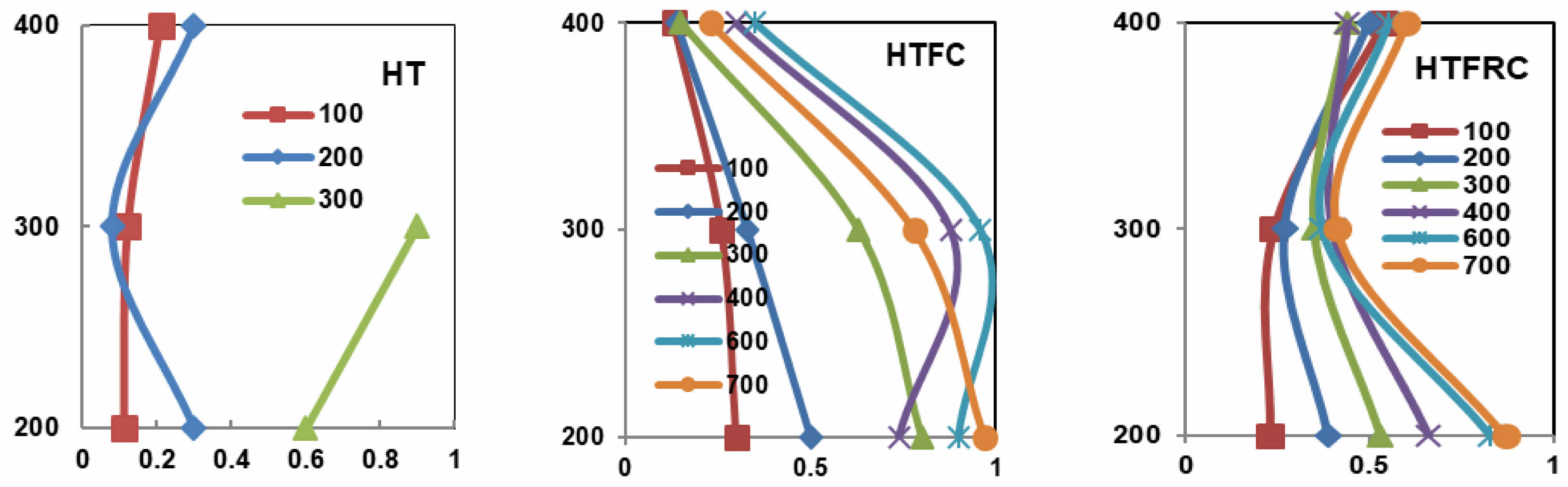
Poisson’s ratio effect at different load levels
Poisson’s ratio effect at different load levels of HT, HTFC and HTFRC specimens with height of 200, 300 and 400 mm are presented in Fig. 4.In HT columns at 100 kN load Poison ratio is marginally increased by increasing height of the specimens. But in 200 kN load the poison ratio is reduced, in 300 mm height and again increase in 400 mm height and lesser than 200 mm height column. Poison ratio is directly increased when height of column is increased in 300 mm column. In HTFC columns poison’s ratio are reduced by increasing the height of the column up to 400 kN load levels. In 600 kN and 700 kN load levels, enormously increase in poison ratio in 300 mm and 200 mm column and marginal reduction in 400 mm height than 300 mm column.
The trends in HTFRC columns are opposite to the trends of HTFC columns in poison’s behavior at different load intervals. The poison’ ratio is increasing with the increase in load for 200 mm height column. The poison’s ratio is lower in 300 mm column and again increase in 400 mm column. The variation in poison ratio is more in 200 mm column, lesser than 200 mm in 300 mm column and marginal variation in 400 mm column at load intervals. Results clearly showed that the effect of fibre reinforced concrete in steel tube composite columns.
Failure modes
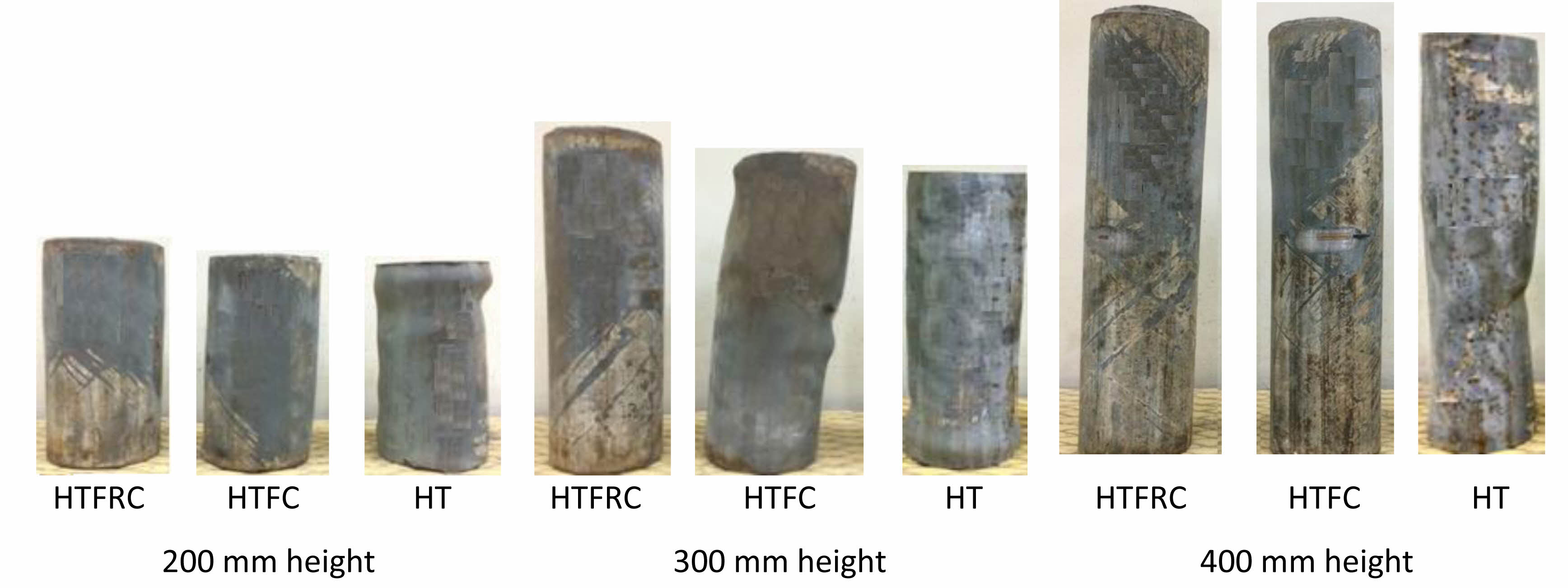
Failure pattern of HT, HTFC and HTFRC column specimens loaded up to ultimate loads are shown in Fig. 5. Hollow tube specimens bulging more on the outside of top and bottom portion the specimens in 200 mm height and total vertical shortening is 17 mm. In 300 mm minor bulging occurred top and bottom also in three places in between top and bottom slightly. Minor bulging occurred at bottom edge and also slight bulging occurred at 50 mm interval in the middle portion. The vertical shortening in ultimate load is 16 mm. In 400 mm height hollow tube, inside buckling was occurred near the middle portion because of slenderness effect. The total height reduction is 22 mm.
In HTFC 300 mm height column, uniform minor buckling occurred due to ultimate load. Total shortening of height is 8 mm. Buckling was occurred at top and bottom and also at middle portion due to crusting of concrete and concrete internal pressure. Total shortening of height is 20 mm. In 400 mm height HTFC column minor uniform lateral buckling occurred many placed due to pressure developed by the filled concrete after crushing. Total height reduction is 17 mm.
Uniform expansion taken place on the steel tube because of uniform pressure developed inside by FRC core. Same type of failure pattern was observed in all columns with different heights. Total shortening of heights in 200, 300 and 400 mm columns are 6 mm, 6 mm and 11 mm, respectively.
The percentage reduction in height 200 mm, 300 mm, and 400 mm for HT is 3.50%, 5.33% and 5.50%, for HTFC are 4.00%, 6.67% and 6.75% and for HTFRC are 3.00%, 2.00% and 2.75%, respectively. HTFRC showed better performance than other columns.
Strength comparison by Design Code
In this section, a succinct outline of the main mathematical formulas used for designing steel-concrete composite columns is presented, adhering to both American and European standards. More comprehensive guidelines pertaining to the design procedures can be found in the respective code documents. The design criteria analyzed in this study provide diverse equations for evaluating the compressive strength of columns. However, these equations all rely on integrating the influences of both steel and concrete to ascertain the load-bearing capacity of the columns. The obtained peak experimental values (referred to as Pthe) were calculated by summing up the individual ultimate axial capacities of the steel tube and concrete, as defined by the equation.

In the equation, Ac represents the cross-sectional area of the concrete core, As stands for the cross-sectional area of the steel tube, Fc denotes the concrete compressive strength, and fy represents the yield stress of the steel tube. It has been noted that the calculated outcomes exceed the actual experimental results. As per the European code (EC04), for columns under axial compressive loads, the design resistance of circular concrete-filled steel tube columns is determined by
Where ηc is a concrete-confinement factor and ηa is a steel resistance reduction factor. NED is the design resistance.
Georgios Giakoumelis in 2003 put forth an adjusted factor for the formula provided by ACI to calculate the axial load capacity of a concrete-filled tube (CFT) column, accounting for the influence of concrete confinement. The altered equation reads as follows

Nu (ACI) = 0:85Acfc + þ As fy
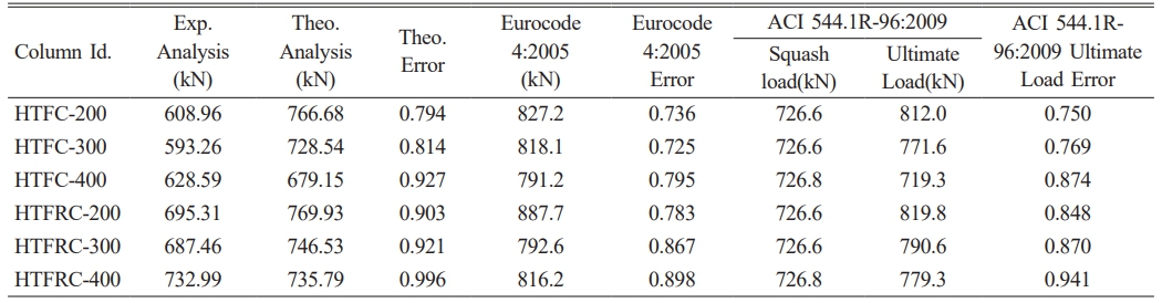
For all columns tested in the experimental part of the investigation, the strength predicted by code resistance models was determined. Results were compared and tabulated in Table 6.
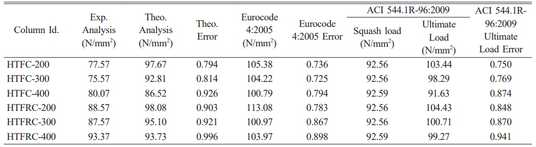
Table 7 presents the comparison of compressive stress with theoretical, ACI and European codes were solved and found that the error percentage was 0.9 to 0.99 respectively.
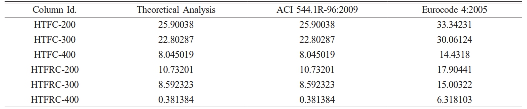
In the context of comparing with experimental outcomes, the equations were solved using unitary partial safety factors. The percentage of confinement was determined by the quotient of the disparity between experimental and theoretical values, divided by the theoretical values. This result was then documented in Table 8.
The confinement percentage range specified by the ACI Code, ranging from 0.38% to 25.90%, does not take into account the effect of confinement. Furthermore, the ACI Code incorporates a factor to account for the reduction in strength due to the softening influence of creep in concrete under sustained compressive loads. However, the ACI approach seems overly cautious because it does not consider the confinement of concrete, leading to a potentially conservative estimation of axial load-carrying capacity.
|
Fig. 1 Experimental Test Set Up for Column under Uniaxial Compression. |
|
Fig. 2 Load Vs Vertical Shortening of Hollow and Concrete/FRC filled Steel Tube Columns. |
|
Fig. 3 Load-Vertical and Horizontal Strain Behavior of Hollow and Concrete Filled Columns. |
|
Fig. 4 Poisons Ratios Effect of Columns under Different Load Intervals. |
|
Fig. 5 Failure patterns of columns subjected to uniaxial compression. |
|
Table 1 Mechanical Properties of Concrete with and without Steel Fibres. |
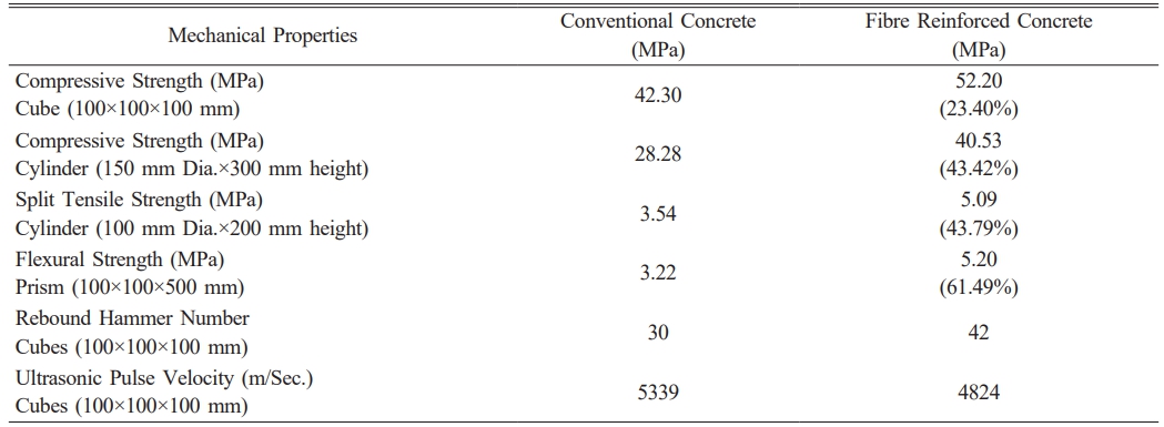
Note: Values in (---) are the percentage increase in strength of FRC compared to plain concrete |
|
Table 2 Geometric Properties of Specimens. |
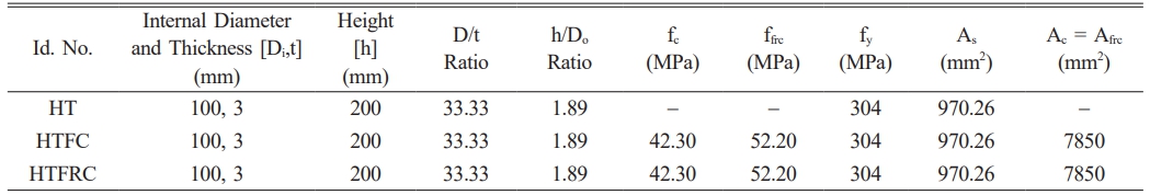
fc = compressive strength of concrete, ffrc = compressive strength of fibre reinforced concrete, As = Area of Steel tube Ac = Area of Concrete core Afrc = Area of fibre reinforced concrete core |
|
Table 3 Ultimate Load Carrying Capacity of Columns Tested under Uniaxial Compression. |
|
Table 4 Parameters on Concrete and FRC Filled Column Specimens. |
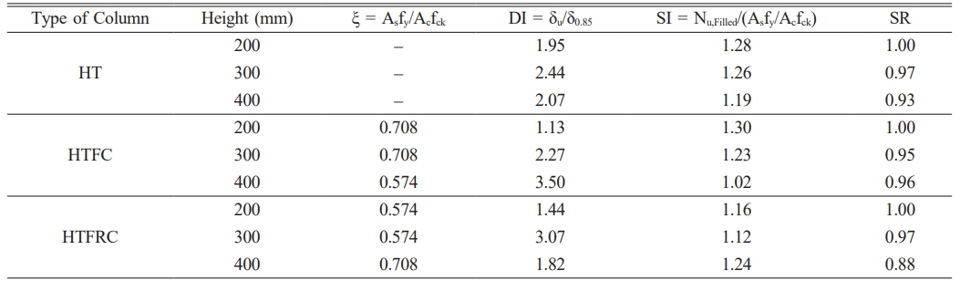
Note: ξ – Constraining factor, DI – Ductility index, SI – Strength Enhancement Index, SR – Strength ratio |
|
Table 5 Ultimate Load, Stiffness and Ductility Index of Column Specimens. |
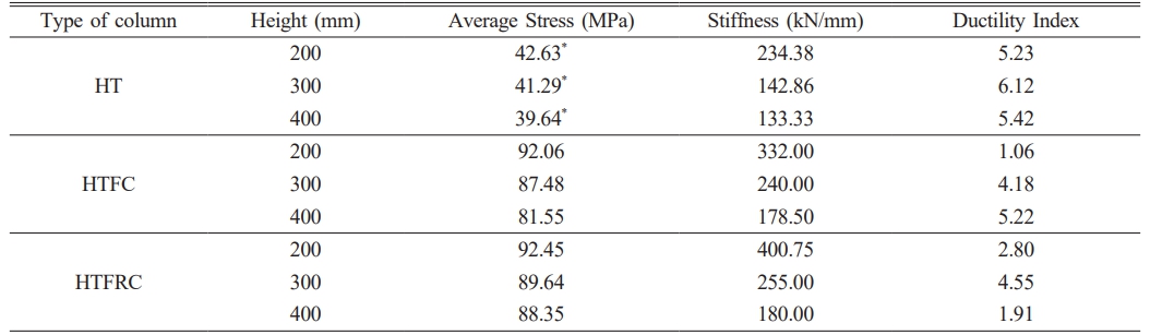
Note: * Stress calculated by considering total area including hollow portion of the steel tube |
Based on the experimental results the following conclusions are arrived.
● The percentage increase in cube compressive strength, cylinder compressive strength, split tensile strength and flexural strength in FRC are 23.40, 40.53, 43.79 and 61.49, respectively, when compared to conventional concrete specimens.
● When compared to HTFC columns, HTFRC columns showed increase in ultimate load in all the height of the specimens. The strength enhancement index (SI) and strength ratio (SR) decreases by increasing height of the column in all type.
● Compared to HTFC, the HTFRC showed 20.48%, 6.25% and 0.56% increased in stiffness for 200, 300 and 400 mm height columns, respectively.
● The percentage increase in ultimate load carrying capacity of HTFRC columns of height 200 mm, 300 mm and 400 mm when compared with corresponding height of HTFC columns are 0.96, 2.46 and 8.34, respectively.
● The vertical shortening of 200 mm, 300 mm and 400 mm height columns are for HT columns 3.5%, 5.33% and 5.50%, for HTFC 4.00%, 6.67% and 6.75% and for HTFRC 3.00%, 2.00% and 2.75%, respectively.
● The strength enhancement index (SI) and strength ratio (SR) decreases by increasing height of the column in all type.
● The reason behind this is that steel fibers play a crucial role in managing the formation of cracks in concrete and slowing down the sideways expansion of the concrete material. It's important to highlight that the extent of sideways deformation in the steel tube during peak load rises as the volume fraction of steel fibers increases.
● The trends in HTFRC columns are opposite to the trends of HTFC columns in poison’s behavior at different load intervals.
● Increasing the height of the columns leads to a reduction in both their stiffness and ultimate load-carrying capacity. The findings suggest that the inclusion of steel fibers in the concrete does not significantly impact the ultimate load-bearing capacity of the columns. However, it is evident that steel fiber-reinforced concrete exhibits superior structural behavior when compared to both hollow steel tube columns and control columns filled with regular concrete.
● The load capacities of HTFC columns, HTFRC columns were verified with predicted values using Eurocode, and ACI codal provisions.
● Based on the results for HTFC columns, HTFRC columns, the EC4 gives us lower than that from experiments. Based on this it was suggested that EC04 can reliably predict the axial capacity of CFT columns using concrete strength.
The authors wish to thank Department of Science & Technology, Government of India for funding the Research Infrastructure under the Scheme entitled "Funds for the Improvement of S&T Infrastructure (DST-FIST)" Ref. No. SR/FST/ College - 110/2017. And AICTE Government of India under the scheme Modernisation and Removal of Obsolenscence (AICTE-MODROBS) Programme Sanction order (No:F.No.9.66/RIFD/MODROBS/Policy-1/2017-18).
- 1. ACI 544.1R-96(Reapproved) (2009) Report on Fibre Reinforced Concrete–Reported by ACI Committee 544.
- 2. Eurocode 4:2005 Design of composite steel and concrete structures - December 2004.
- 3. M. Saafi, H.A. Toutanji, and Z. Li, ACI Mater. J. 96[4] (1999) 500-509.
- 4. Y. Lu, N. Li, S. Li, and H. Liang, Constr. Build. Mater. 95 (2015) 74-85.
-

- 5. S. Guler, E. Lale, and M. Aydigan, Adv. Steel Constr. 9[1] (2013) 14-25.
-
- 6. S.R. Gopal, KSCE J. Civ. Eng. 21[3] (2017) 923-927.
-
- 7. N.A. Alwash and H.I. AL-Salih, Constr. Eng. (CE) 1[2] (2013) 37-51.
- 8. K.S. Nakahara, S. Morino, and I. Nishiyamakino, J. Struct. Eng. 130[2] (2004) 180-188.
-
- 9. G. Campione, L.L. Mendola, L. Sanpaolesi, N. Scibilia, and G. Zingone, Mater. Struct. 35 (2002) 332-337.
-
- 10. E. Ellobody and M.F. Ghazy, J. Constr. Steel Res. 76 (2012) 167-176.
-
- 11. E. Ellobody and M.F. Ghazy, Adv. Struct. Eng. 16[3] (2013) 427-440.
-
- 12. T. Zhong, B. Uy, L.-H. Han, and Z.-B. Wang, Thin-Walled Struct. 47[12] (2009) 1544-1556.
-
- 13. S.R. Gopal and P.D. Manoharan, Steel Compos. Struct. 4 (2004) 37-48.
-
- 14. V.K.R. Kodur and T.T. Lie, J. Struct. Eng. 122[7] (1996) 776-782.
-
- 15. Y. Wei, Y. Zhang, J. Chai, G. Wu, and Z. Dong, Compos. Struct. 244 (2020) 112311.
-
- 16. J. Yang, J. Wang, and Z. Wang, Compos. Struct. 246 (2020) 112373.
-
- 17. S. Barua, K. Mahmoud, and E. El-Salakawy, J. Bridge Eng. 26[7] (2021) 04021033.
-
- 18. J. Wei, Z. Xie, W. Zhang, X. Luo, Y. Yang, and B. Chen, Eng. Struct. 230 (2021) 111599.
-
- 19. A. Raza and Q.U.Z. Khan, Mater. Struct. 53 (2020).
-
- 20. S.L. Prabha, J.K. Dattatreya, M. Neelamegam, and M.V.S. Rao, J. Struct. Eng. (Madras) 36[5] (2009) 333-341.
- 21. S.L. Prabha, M. Gopalakrishnan, and M. Neelamegam, ACI Mater. J. 4 (2020) 37-46.
- 22. R. Al-Rousan, Procedia Manuf. 44 (2020) 623-630.
-
- 23. F. Faleschini, M.A. Zanini, L. Hofer, and C. Pellegrino, Constr. Build. Mater. 243 (2020) 118296.
-
- 24. Z. Kharal and S.A. Sheikh, J. Compos. Constr. 24[1] (2020) 04019059.
-
- 25. A. Mohan, S. Karthika, J. Ajith, and L. Dhal, Mater. Today Proc. 22 (2020) 904-911.
-
- 26. V.S. Karthika, A. Mohan, R.D. Kumar, and C. James, J. Green Eng. 9[4] (2019) 514-525.
- 27. S.L. Prabha, M. Surendar, and G. Prabha, J. Ceram. Process. Res. 24[5] (2023) 884-893.
-
- 28. K. Chandrasekaran, S.L. Prabha, and M. Neelamegam, Mater. Plast. 58[4] (2021) 158-170.
-
- 29. C. Kiruthika, S.L. Prabha, and M. Neelamegam, Mater. Today Proc. 43 (2021) 1622-1625.
-
- 30. M. Siva, T. Sasikumar, P.S. Aravind Raj, and R. Divahar, Mater. Today Proc. 33[1] (2020) 189-195.
-
- 31. M. Siva, Int. J. Recent Technol. Eng. (IJRTE) 8[3] (2019) 8614-8618.
-
- 32. S.L. Prabha, A. Mohan, G. Velrajkumar, and M.H. Zubair, J. Environ. Prot. Ecol. 23[6] (2022) 2380-2388.
- 33. R. Gopalakrishnan, A. Mohan, L.P. Sankar, and D.S. Vijayan, J. Environ. Prot. Ecol. 21[6] (2020) 2153-2163.
- 34. R. Divahar, P.S. Aravind Raj, M. Siva, and S.I. Xavier, Indian J. Environ. Prot. 41[10] (2021) 1120-1125.
- 35. D.S. Vijayan, A. Mohan, J.J. Daniel, V. Gokulnath, B. Saravanan, and P.D. Kumar, Adv. Mater. Sci. Eng. (2021) 1-12.
-
 This Article
-
2025; 26(1): 148-156
Published on Feb 28, 2025
- 10.36410/jcpr.2025.26.1.148
- Received on Aug 8, 2024
- Revised on Sep 26, 2024
- Accepted on Dec 18, 2024
Services
- Abstract
introduction
research significance
material properties
experimental results and discussion
conclusions
- Acknowledgements
- References
- Full Text PDF
Shared
Correspondence to
- G. Prabha
-
Assistant Professor, Easwari Engineering College, Chennai, Tamil Nadu, India
Tel : 9841442944 - E-mail: prabhagandhi1985@gmail.com
Clean-Energy Research Institute(CRI), Hanyang University, 222, Wangsimni-ro, Seongdong-gu, Seoul, 04763, Korea
E-mail: jcpr@hanyang.ac.kr