


- Layer by layer fabrication of zirconia by different UV light position approaching in digital light processing method
So-Young Koa, Kyoung-Jun Jangb and Sang-Jin Leea,c,*
aDepartment of Advanced Materials Science and Engineering, Mokpo National University, Muan 58554, Republic of Korea
bResearch Institute, 3D Controls Co., Ltd, Busan 46721, Republic of Korea
cResearch Institute of Ceramic Industry and Technology, Mokpo National University, Muan 58554, Republic of KoreaThis article is an open access article distributed under the terms of the Creative Commons Attribution Non-Commercial License (http://creativecommons.org/licenses/by-nc/4.0) which permits unrestricted non-commercial use, distribution, and reproduction in any medium, provided the original work is properly cited.
The digital light processing (DLP) 3D printing method can be used to achieve continuous ceramic laminations during additive manufacturing. However, it has limited applications because its green body, which is photocured by adding a resin and photoinitiator to the ceramic powder, cracks during the debinding process. In this study, we used four types of acrylic resins with low functional groups and mixed 82 wt% zirconia powder with the photoinitiator and dispersant to prepare a slurry. Under a certain content of photoinitiator, the photocured zirconia green body was prepared by controlling the light intensity conditions of 32 W/m2 and 38 W/m2, and the light exposure time of 3s and 7s, respectively. Furthermore, we conducted experiments focused on the condition of photocuring green body according to the printing approach based on the UV light position, as well as cracking of the green body after the debinding process. The position of the UV light influenced the continuous lamination behavior and intervention of oxygen during photocuring, and based on these results, we investigate the differences in the laminated layer interphase of the photocured green body and its relationship to cracking with the debinding behavior.
Keywords: Ceramic 3D printing, Digital Light Processing (DLP), Photocuring, Zirconia, Debinding.
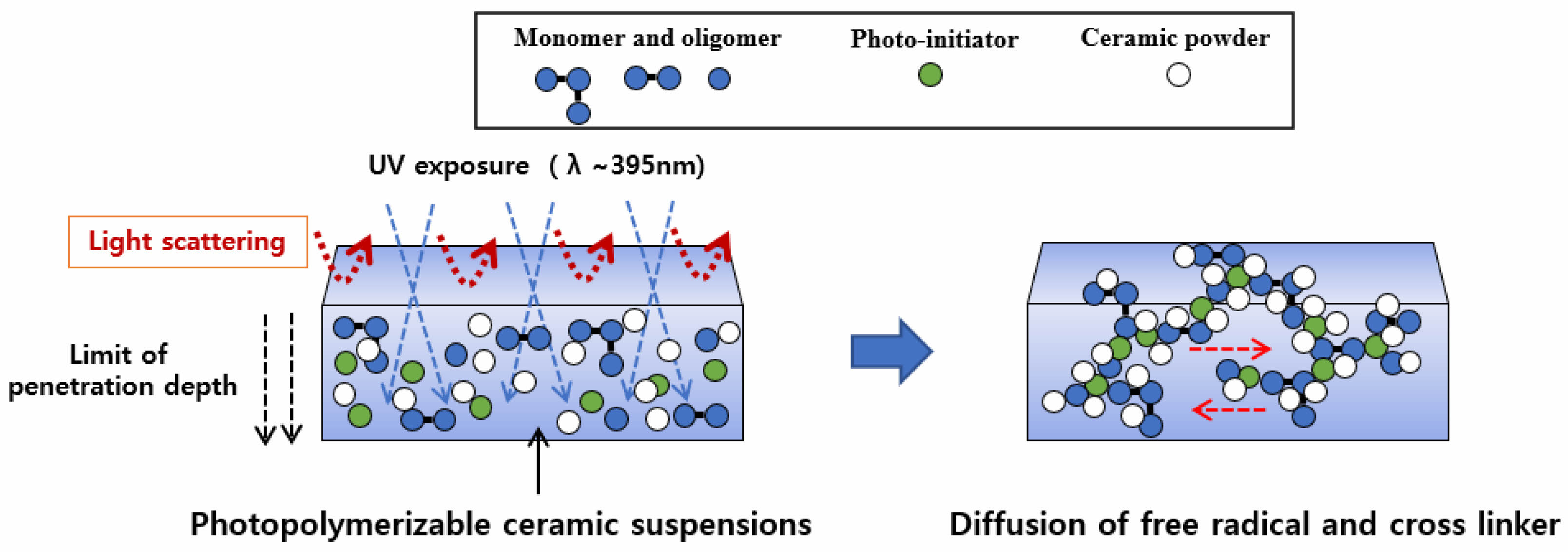
Ceramics have almost no ductility and are very brittle, making them fragile. Furthermore, their low plasticity makes continuous layer by layer fabrication difficult, in particular, as for precision in shape [1, 2]. To overcome these limitations, a digital light processing (DLP) method was introduced wherein photocurable, liquid-type resins were mixed into a ceramic powder, and cured. In the slurry-based DLP process, a slurry prepared by mixing a photoinitiator and ceramic powder with a photocurable resin, as shown in the schematic diagram in Fig. 1, absorbs and scatters light with wavelengths in the ultraviolet (UV) range, thereby accelerating the decomposition of the photoinitiator and generating free radicals. These free radicals break the double bonds of the monomers and cause cross-linking bonding. In short, the DLP method is used to solidify and stack the ceramic slurry instantaneously by triggering a polymerization reaction [3-8]. The resulting multilayer ceramic photocured green body exhibits a high degree of precision and reasonable handling strength through the relatively simple process. For this reason, it is the most appropriate method for manufacturing ceramic layer by layer samples with complex shapes [9].
Acrylates, which are photoreaction polymers, have a wide range of application in the ceramic layer by layer process owing to their fast curing speed and ability to control the properties according to the type of monomer and oligomer and number of reactive groups. However, the conversion rate is low because it is difficult to achieve full curing because of the effect of oxygen in the air during radical curing [10-12]. Ceramic layer by layer fabrication based on DLP process requires a debinding process to remove the acrylate-type binder present in the photocured green body through heat treatment [13-18]. In previous research, a very slow heating rate (0.2 to 0.5 ℃/min) was set during the debinding process to prevent cracking of the green body, which had the disadvantage of requiring a long debinding process. Despite the long debinding process, cracks were generated during the pyrolysis-removal process of the cured resin. These problems were also reflected after sintering, causing serious defects in the sintered body accompanying sintering shrinkage [3, 5, 19, 20]. Owing to these postprocessing issues, ceramic materials are utilized less than plastics and metals in additive manufacturing, and the sintering-based manufacturing of ceramics in the 3D printing process has not been studied widely.
Process variables in the DLP process that affect debinding include the types and contents of the acrylic resin and photoinitiator used, light intensity and light exposure time during the printing process, heating conditions for debinding, and printing approach method [3, 5, 9, 16, 17, 21]. Controlling these process variables including heat-treatment is a prerequisite for a crack-free debinding process. Although previous studies established the conditions under which DLP could be used for printing, the problem of cracking during the debinding process still exists. Although the process variables can be controlled to prevent the cracking, this paper focuses on a printing approach based on the position of the UV light. In the case of ceramic layer by layer fabrication applying DLP, top-down and bottom-up printing approaches depending on the position of the UV light source are of interest. Considering this, we studied the differences in photocuring mechanism based on the position of the light source with the effects of light intensity and light exposure time for crack-free debinding zirconia 3D printing output.
|
Fig. 1 Photocuring mechanism of DLP ceramic 3D printing process. |
Slurry preparation
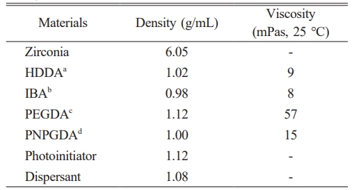
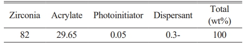
A photocurable slurry was prepared by mixing zirconia powder (3Y-TZP, D50=0.4 μm), 0.05 wt% photoinitiators (Irgacure TPO, Ciba Specialty Chemicals, Inc., Switzerland) and 0.3 wt% dispersant [22] in a liquid-type resin containing four types of photocurable acrylic materials including 1,6-Hexanediol diacrylate (HDDA). The physicochemical properties of each material are summarized in Table 1 and the composition of the slurry is summarized in Table 2 based on weight fraction. Mixing was performed by ball milling using zirconia balls at 120 rpm for 12 h to prepare the slurry. Resins with low viscosity were used to maximize the content of zirconia powder, which was mixed up to 82 wt%. And, the four kinds resin system were designed for staged thermal decomposition. After milling, the zirconia balls were removed by 230 mesh sieving to finally prepare the slurry for DLP 3D printing.
Layer by layer fabrication process
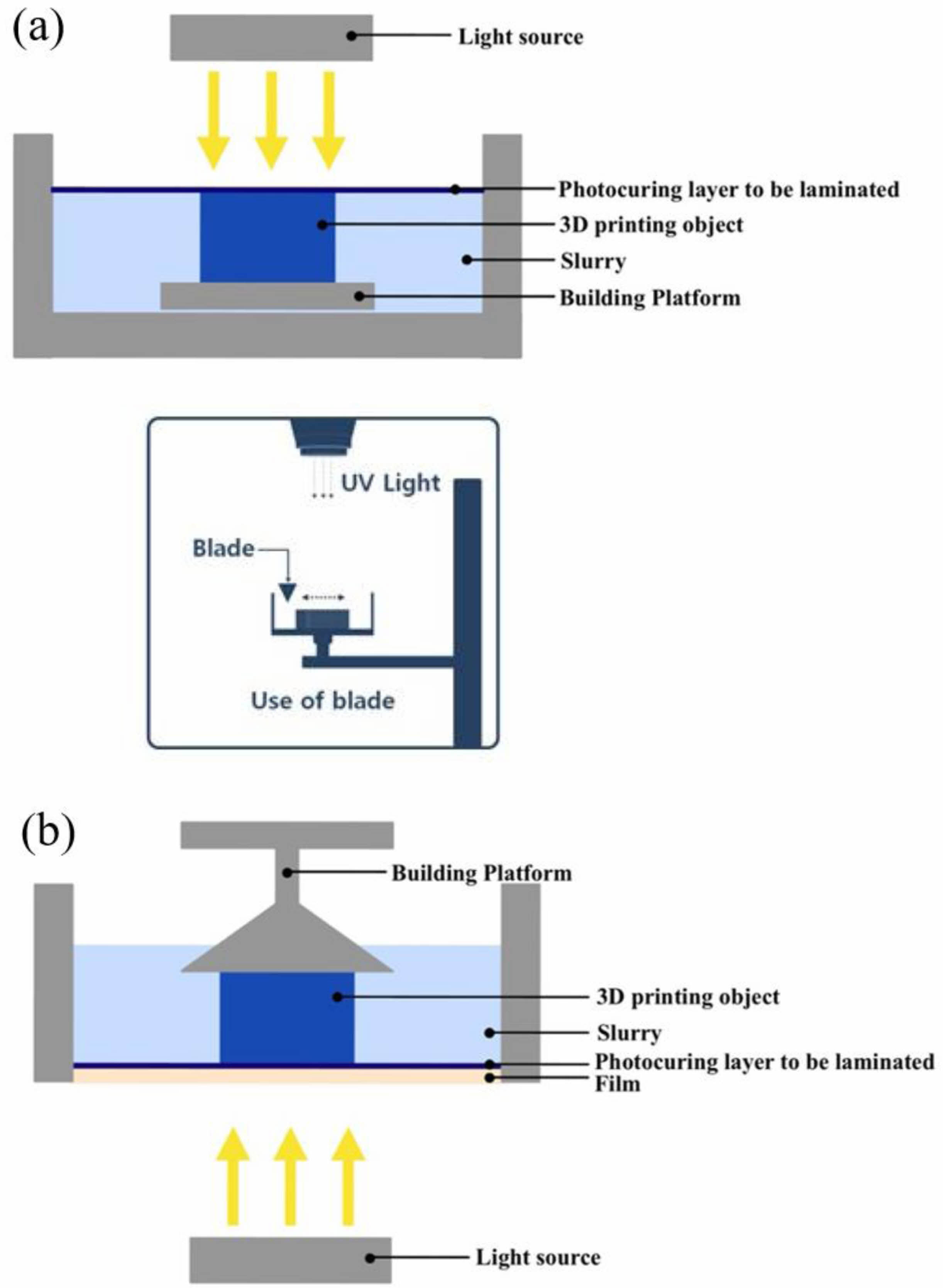
DLP 3D printing methods are applied to top-down and bottom-up approaches depending on the position of the UV light source, and a schematic diagram of both approach methods is shown in Fig. 2. In the top-down method, curing is performed by exposing the UV light source from the top to bottom. After curing, the building platform is moved downward by an amount equivalent to the cured thickness. The top-down method, similar to tape-casting, supplies slurry on the uniform surface through the repeated left and right movements of the blade whenever a layer is added to the platform. The speed of the blade and the shear stress occurring between the blade surface and the slurry affect the layer thickness. The viscosity of the slurry also affects the layer thickness [23]. As the building platform moves downward, the printed object is immersed in the slurry, and the cured layer is continuously exposed to air during the curing process. In the bottom-up method, the UV light source is positioned at the bottom, below the plate containing the slurry. The building platform is moved downward to obtain a certain thickness of slurry on the plate containing, and the slurry between the lower film (FEP film, Si-based composite film) and building platform is cured using UV light. The cured layer is then removed from the film, attached to the building platform, and moved upward. These processes are repeated to perform 3D printing lamination [14, 24, 25]. In the process of separating the film and adhering to the building platform, the printed object is periodically under stress. This causes unwanted stress and deformation of the printed object during printing [3], and this is characterized by the absence of contact with air because the curing process takes place inside the slurry.
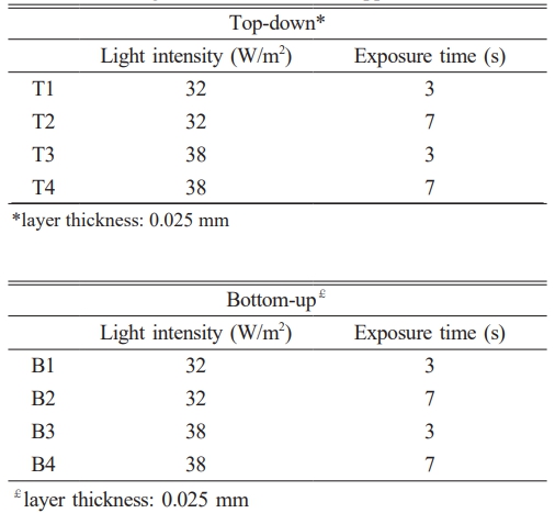
In this study, two kinds of printing equipment, TD6 (3DCONTROLS, Korea) for top-down system and IMC (Carima, Korea) for bottom-up system, were used. The specification of each equipment is listed in Table 3. During curing, the absolute value of light intensity varies depending on the printing approach method. Therefore, to maintain the same light intensity, we measured the light intensity using a light intensity meter (BLUEWAVE, StellarNet, Inc., USA) and adjusted the power. The printing conditions were the same for both the top-down and bottom-up approach methods. Under light intensity conditions of 32 W/m2 and 38 W/m2, the exposure time was changed to 3 s and 7 s, respectively, to proceed with the printing. The detailed printing conditions are summarized in Table 4.
Debinding & sintering
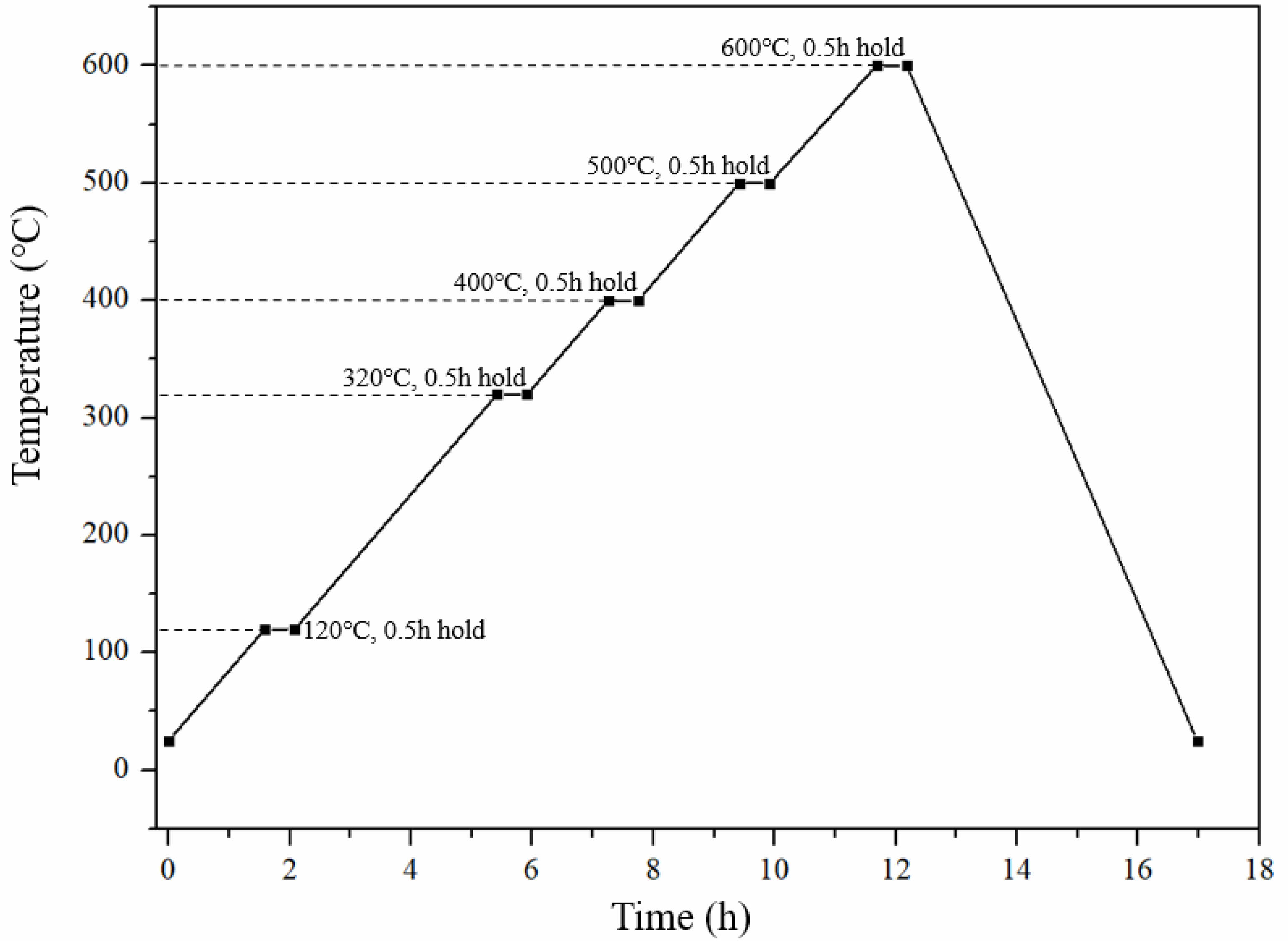
The debinding process conditions for the printed object are presented in Fig. 3. Debinding was performed in air, at a heating rate of 1 ℃/min, the temperature was maintained at 120, 320, 400, 500, and 600 ℃, respectively, for 30 minutes. The heating schedule was determined based on the temperature of thermal decomposition of each resin and also based on the results of a thermogravimetric analysis (Fig. 4). For the sintering of the sample after debinding, the temperature was raised to 1,500 ℃ at a heating rate of 3 ℃/min and maintained for 2 h, followed by furnace cooling.
Characterization
To examine the debinding behavior, photocured green body samples were prepared by changing only the zirconia solid content to 55 wt% in order to clearly measure the degree of weight loss. Using a thermogravimetric analyzer (TGA, STA 409PC, Netzsch, Korea), measurements were conducted in air at a heating rate of 5 ℃/min in a range of 30 to 1200 ℃. To examine the difference in the molecular bonding of the photocured green body according to the printing method, each sample was powdered and subjected to a Fourier transform infrared (FT-IR, VERTEX 80v, Bruker, USA) analysis in a wavelength range of 4000~500 cm-1. The hardness of each green body was measured using a hardness tester (GS-702N, TECLOCK, Japan). And Vernier Calipers (CD-20CP, Mitutoyo, Japan) was used to measure the size of green body in order to compare the size difference with the program size (10 mm by 10 mm). Microstructural analyses of the photocured green body and green body after debinding were performed using a scanning electron microscope (SEM, EM-30N, Coxem, Korea). After fixing the sample with carbon tape on an aluminum holder, it was coated via Au-Pd sputtering. Because it was difficult to handle the sample after debinding, the sample was prepared by sintering the green body after debinding by increasing the temperature to 1,150 ℃ at a heating rate of 3 ℃/min and maintaining it for 2 h. The density of the sintered zirconia body was measured by the Archimedes method. To calculate relative density, the measured density was compared with the theoretical density of 3Y-TZP (6.05 g/cm3). The flexural strength of the sintered body was measured to determine the presence of microcracks. Bend bar samples for the measurement were prepared by polishing the surfaces of the samples using abrasive SiC paper no. 2000, and the flexural strength was measured by a four-point flexural strength test with a universal testing machine (Instron 4461, Norwood Co., USA) at a cross-head speed of 0.5 mm/min using a fixture with an inner span of 10 mm and an outer span of 20 mm.
|
Fig. 2 DLP 3D printing methods: (a) top-down (use of blade), (b) bottom-up. |
|
Fig. 3 Heating schedule for debinding process of zirconia green body photocured by DLP method. |
|
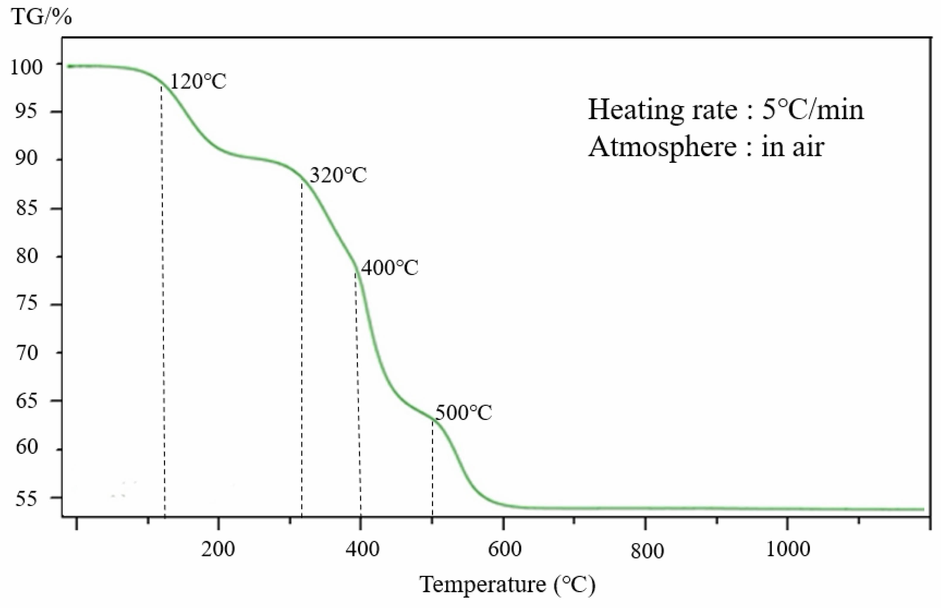
Fig. 4 Thermal analysis result of zirconia green body photocured by DLP method. |

A thermogravimetric analysis was performed to observe the debinding behavior of the photocured green body, and the results are presented in Fig. 4. As the temperature increased, weight loss was detected owing to the removal of the photocured resin. The weight loss occurred in stages, at 120, 320, 400, and 500 ℃. Weight loss was not detected beyond 600 ℃. The four step weight loss is due to the four kinds of resin having deferent thermal decomposition temperature. Maintaining the weight loss in stages by adjusting the type of resin is one way to inhibit cracking of the green body. The analysis results of the printed objects obtained by the different printing approaches were almost identical.
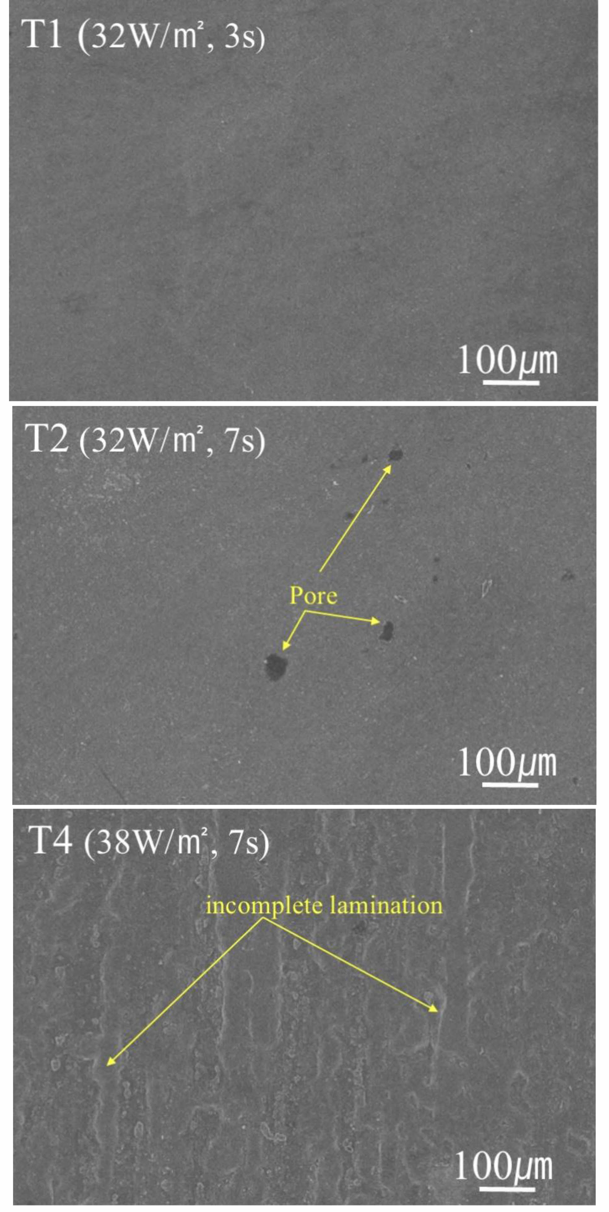
The microstructures of the top surface of the photocured green body depended on the printing approach, light intensity, and exposure time, and are presented in Figs. 5 and 6. Slight changes were observed in the microstructures of the top surfaces with increase in the light intensity and exposure time. These changes were more noticeable in the bottom-up approach method than in the top-down method. In the green body prepared by the top-down method, shown in Fig. 5, pores and incomplete laminations were observed as the light intensity and exposure time increased. In the bottom-up method, these defects were more extensive, as shown in Fig. 6. These defects were believed to have been caused by overcuring. In particular, in the case of the bottom-up method, which caused severe defects, the incomplete lamination phenomenon was more severe. The reason for this was that the photocured green body layer to be laminated was strongly cured on the FEP film during the printing process. It did not completely adhere to the building platform, but remained on the film and was not properly bonded to the previous laminated layer. Incomplete lamination caused unwanted defects and deformations by overcuring in the printed object, resulting in uneven density of the photocured green body because of micro delamination between layers.
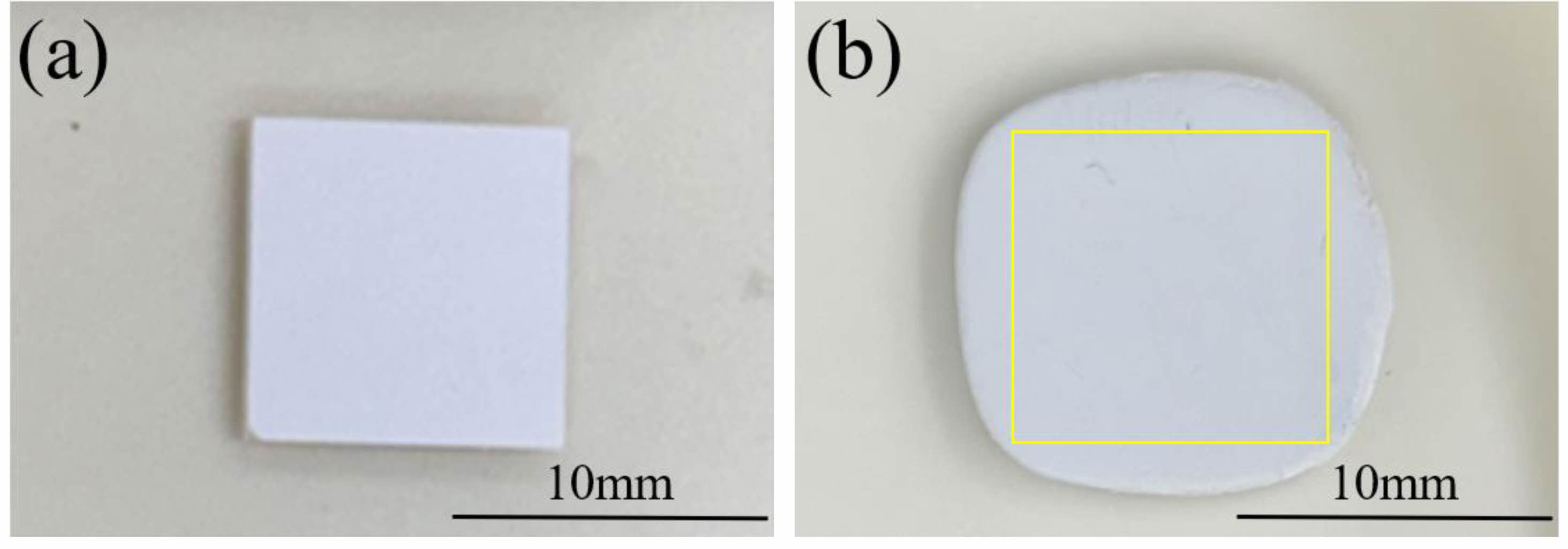
The hardness of the photocured green body at each condition is listed in Table 5. As the light intensity and exposure time increase, the hardness was increased. And the samples photocured by bottom-up process showed higher hardness value. Table 6 shows the final size of photocured green body. In case of the top-down process, the sample size was same with the program size (10 mm by 10 mm). However, the samples prepared by bottom-up process showed over size. The light intensity and exposure time more increased, the degree of oversize also more increased. Photographs of the representative printed objects under top-down and bottom-up conditions are presented in Fig. 7. It is generally believed that the presence of solid ceramic powder in the slurry can cause UV light scattering because of the large refractive-index difference between the ceramic powder and photocurable resin, which can affect the printing accuracy. The green body can be cured beyond the exposure area by the light scattered from the interface of the resin and powder particles because of the different refractive indices of the materials [17]. When comparing these effects according to the printing approach, it could be seen that the printing accuracy was inferior with the bottom-up method. In the top-down method, there was almost no difference between the designed area and the size of the printed object, regardless of the exposure time. In the bottom-up method, on the other hand, there was a deviation depending on the exposure time, and as the exposure time increased, the overcuring became more severe, resulting in a larger printing size. This indicated that more UV light scattering occurred in the bottom-up method than in the top-down method. Therefore, it is recommended that the printing conditions such as exposure time be adjusted according to the printing approach method.
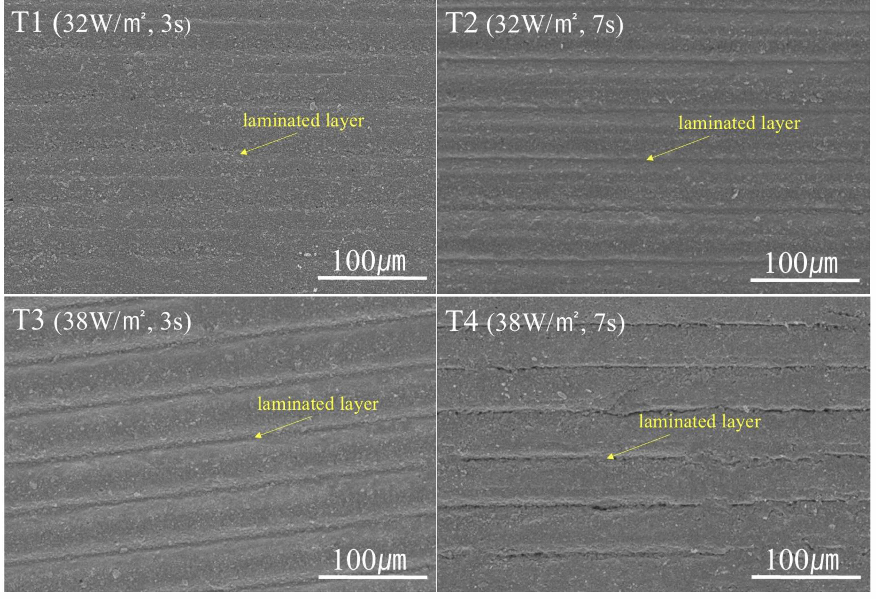
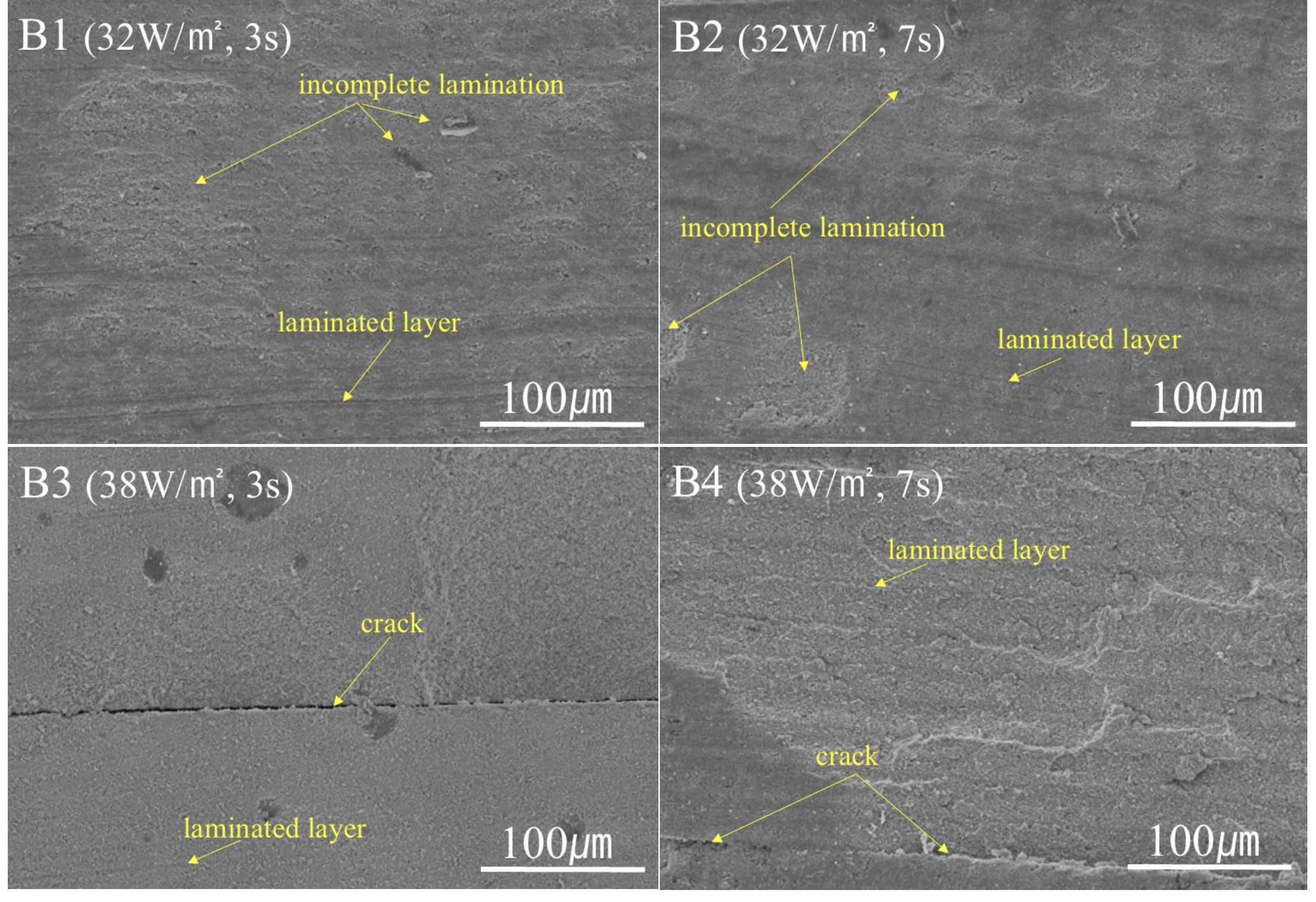
The microstructure of the laminated layer of the photocured green body is presented according to the printing method, light intensity, and exposure time in Figs. 8 and 9. The microstructure of the laminated layer exhibited clear differences depending on the printing method. In the case of the top-down approach (Fig. 8), the microstructure of the laminated layer was more uniform compared to that obtained with the bottom-up method. The laminated layer was also more clearly visible as the light intensity and exposure time increased. In the case of the top-down method, the cured layer interphase was not clearly visible under conditions of 32 W/m2 and 3 s, which indicated uniform mixing between the laminated layers during the photocuring lamination process, similar to a powder compact prepared by press forming. Furthermore, the laminated thickness was set to 25 μm for printing, but the SEM microstructure analysis showed that the laminated layers were at 50 μm intervals. This was considered to be a result of the equipment characteristics such as moving blade [23]. In the case of the bottom-up method (Fig. 9), despite applying the same light intensity and exposure time in printing, the laminated layer was found to be highly irregular in thickness and shape under all conditions, compared to that yielded by the top-down method. The layers were not laminated with a set laminated thickness of 25 μm. Instead, the thickness of each output layer was different, and the horizontality of the layer interphases was also uneven. The cracks seen in the bottom-up method were believed to be the result of defects caused by the phenomenon of the printed object adhering to and remains on the FEP film. The inconsistent and uneven shape of the laminated layer of the photocured green body was determined to be the result of overcuring, which led to inconsistent thickness of the laminated layer.
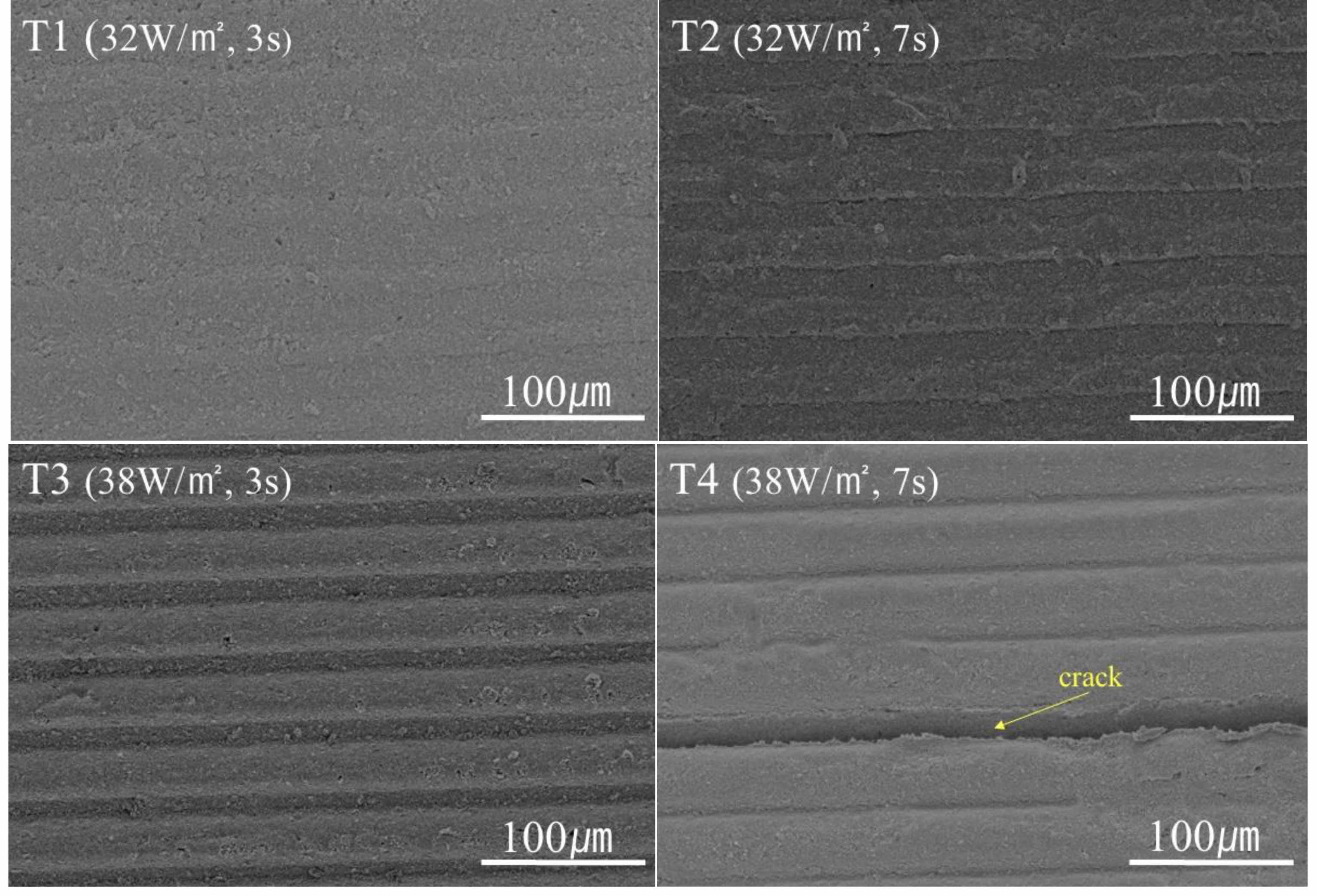
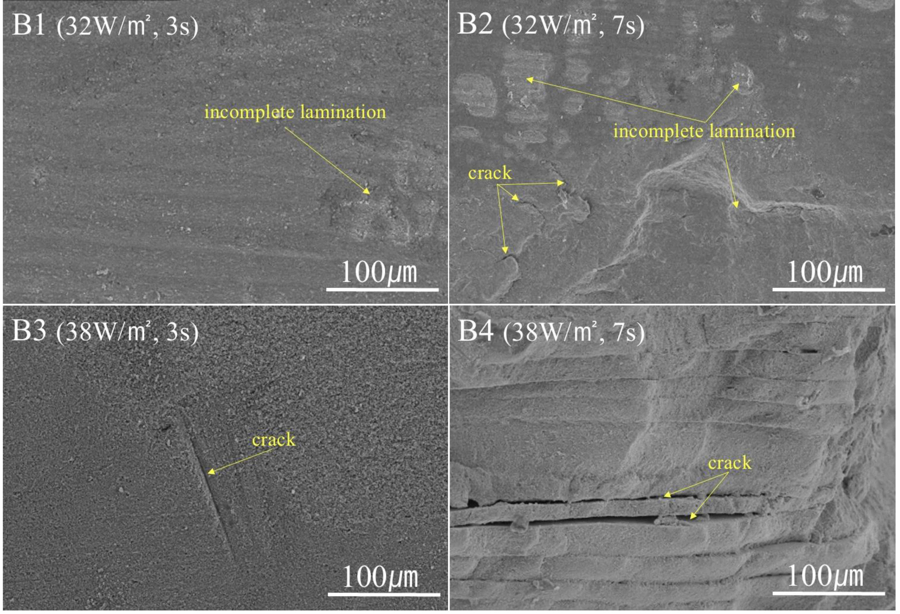
The microstructure of the laminated layer of the printing green body after debinding is presented according to the printing method, light intensity, and exposure time in Figs. 10 and 11, respectively. In the case of the photocured green body sample printed under conditions of 32 W/m2 and 3 s by the top-down method, no cracks are observed after debinding. As overcuring of the printed object was prevented by using a low light intensity and short exposure time, the interphases of the laminated layers were not clear, resulting in an effect similar to that of pressing ceramic powder, and cracks did not occur even after debinding. In the case of the top-down method, cracks did not occur after debinding even in the samples where the laminated layer interphase was observed. On the contrary, when the sample was printed with a relatively high light intensity and long exposure time of 38 W/m2 and 7 s, cracks occurred horizontally along the interphase of the laminated layer after debinding. This indicated that the cause of cracking during debinding was the strong physical bonding between the zirconia powders and the resins (high hardness) by overcured printed zirconia green body. Figure 11 presents images of the samples prepared by the bottom-up method. It can be seen that when the light intensity is low and the exposure time is short, cracking of the green body after debinding occurs along the interphase. On the other hand, when the light intensity is high and the exposure time is long, we observed not only cracks horizontal to the laminated layer, but also transverse cracks. In the case of conditions of 38 W/m2 and 7 s, many cracks are clearly observed. It is believed that the higher the light intensity and longer the exposure time are, the more the printing zirconia green body will be overcured. This makes it difficult to burn out the resins in the photocured green body during the debinding process and causes cracking during debinding. The degree of overcuring is also thought to be affected by the printing method, as relatively more cracks occur in the case of the bottom-up method under the same printing conditions.
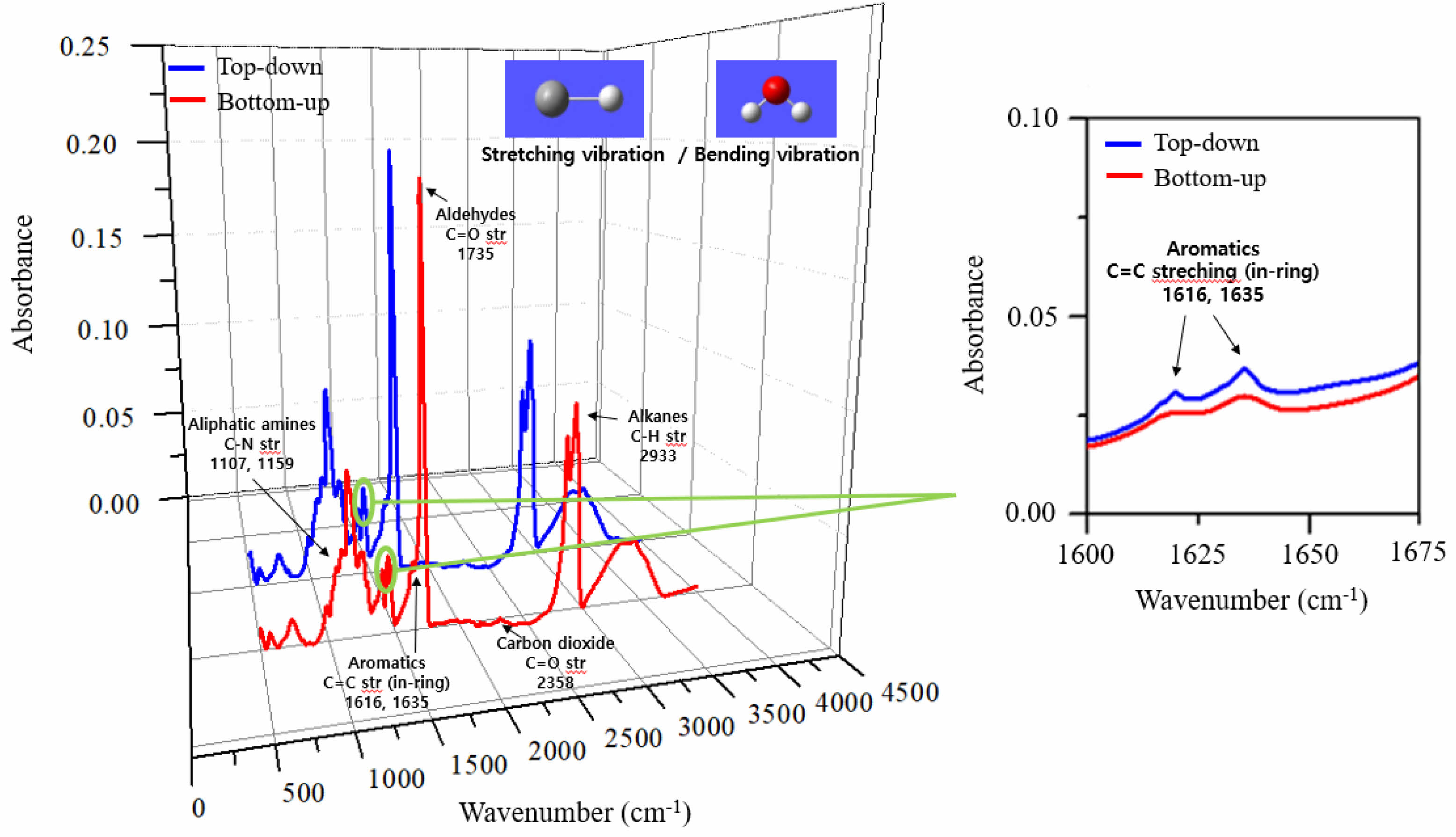
The occurrence of more cracks in the bottom-up method than in the top-down method is attributed to oxygen intervention during the printing process. Oxygen is reported to inhibit the polymerization reaction, thereby interfering with curing [3, 10]. In the DLP process, light with wavelength in the UV region is absorbed, which accelerates decomposition of the photoinitiator to produce free radicals. These free radicals break the double bonds of the monomers and cause cross-linking, which leads to the curing phenomenon. When curing in air, the presence of oxygen leads to incomplete curing and surface tackiness by consuming free radicals and inhibiting the photo-polymerization process [5, 26-28]. Oxygen reacts with carbon-centered radicals in the diffusion step to form peroxyl radicals, and these radicals do not readily participate in the reaction of acrylate monomers and do not break the double bond, thus reducing the efficiency of photocuring [26, 29, 30]. In the top-down method, the interface where photo-polymerization occurs is in direct contact with oxygen, and the curing time is longer compared to that of the bottom-up method. In the bottom-up method, when UV light is irradiated, a vacuum is maintained between the slurry and the film. This leads to the absence of oxygen and increases photocuring accompanying the bonding force with the film. Due to the absence of oxygen, curing tends to occur more easily and quickly compared to curing in the top-down method [17]. Therefore, even if the same light intensity is used for printing, the curing effect in the bottom-up method is better than that of the top-down method, which may result in overcuring. Figure 12 shows the FT-IR results of the photocured green body. When comparing the printed zirconia green body of the top-down and bottom-up methods, it is found that the peak positions are not significantly different; however, the C=C peaks (1616 and 1635 cm-1) for the bottom-up method are smaller in size, for the same light intensity and exposure time. As photocurable acrylic resin progresses, the double bonds (C=C) of the acrylic monomer are consumed [31]. After the UV polymerization, the C=C bonds are converted to a C-C bonds, and the size of the C=C peak becomes smaller. These results show that crosslinks are more actively formed through free radical polymerization, causing overcuring in the bottom-up approach method [12, 31-35].
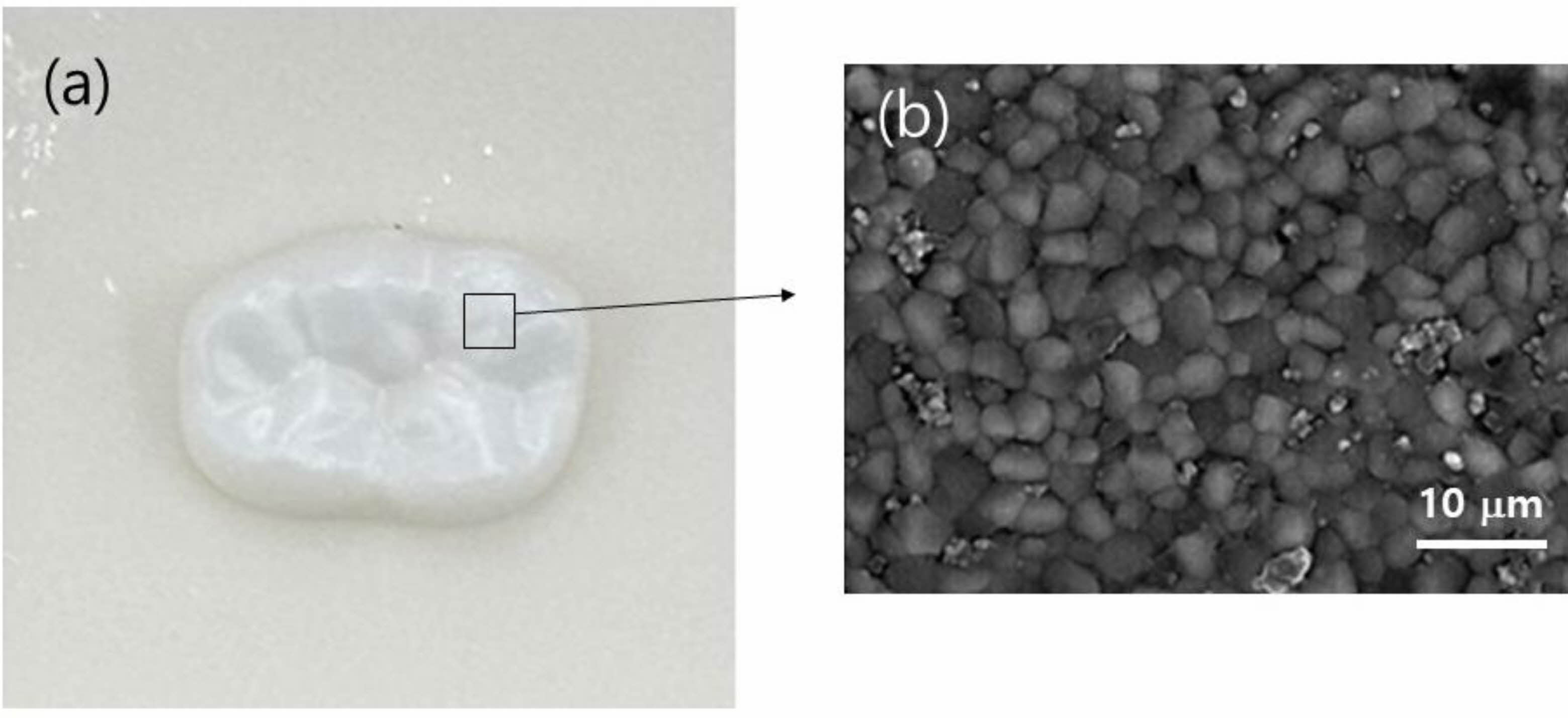
The relative density and flexural strength of the sintered zirconia are listed in Table 7. As a result of debinding the printed green bodies photocured using the top-down method, we obtained dense sintered zirconia without cracks. The measured average flexural strength also showed reasonable value. However, the sample T4 and the printed green bodies photocured using the bottom-up method were fractured with cracks, so the measurement was impossible. Figure 13 shows a photograph of a sintered dental-shaped zirconia sample fabricated by the DLP top-down method on the printing condition of 32 W/m2 for 3 s, as well as the microstructure of the sintered dense body with no cracks.
|
Fig. 5 SEM micrographs of top surface of zirconia green body photocured by DLP top-down method. |

|
Fig. 6 SEM micrographs of top surface of zirconia green body photocured by DLP bottom-up method. |
|
Fig. 7 Photographs of zirconia green body photocured under 38 W/m2 and 7 s, printed by top-down, (b) bottom-up method. |
|
Fig. 8 SEM micrographs of laminated layer of zirconia green body photocured by DLP top-down method. |
|
Fig. 9 SEM micrographs of laminated layer of zirconia green body photocured by DLP bottom-up method. |
|
Fig. 10 SEM micrographs of laminated layer of green body printed by DLP top-down method after debinding process. |
|
Fig. 11 SEM micrographs of laminated layer of green body printed by DLP bottom-up method after debinding process. |
|
Fig. 12 FT-IR results of printed green body photocured by DLP method under a condition of 32 W/m2 and 3 s. C=C peaks (1616 and 1635 cm-1) for the bottom-up method are smaller in size, that is the double bonds (C=C) of the acrylic monomer are consumed to form crosslinks through free radical polymerization in the absence of oxygen. |
|
Fig. 13 (a) Photograph of sintered zirconia fabricated by DLP 3D printing using top-down method under 32 W/m2 , 3 s condition, and (b) its SEM micrograph. |


|
Table 7 Relative Density and Flexural Strength of Sintering Zirconia. |

*average value of five samples at each condition |
To address the problem of cracking during the debinding process of zirconia photocured green body produced by DLP 3D printing, this study was focused on finding the optimal conditions for a crack-free debinding process by controlling the process variables that affect debinding. We tested the top-down and bottom-up approachs according to the position of the UV light source, and the results showed that the top-down method inhibited overcuring relatively more, resulting in fewer cracks during debinding. Light intensity of 32 W/m2 and exposure time of 3 s in the top-down method resulted in a crack-free green body after debinding and a dense sintered zirconia body with no laminated layer interphases. In the case of the bottom-up method, overcuring occurred in all printing conditions, resulting in irregular laminated layers in the photocured green body, and cracks occurred in all green bodies after debinding. The occurrence of relatively fewer cracks in the top-down method than in the bottom-up method may be due to oxygen intervention during the printing process. This oxygen intervention inhibited overcuring by consuming free radicals and generating peroxyl radicals. This decelerates conversion of C=C bonds to C-C bonds, which generates crosslinks. Finally, the printing method based on the position of the UV light source had a strong influence on the photocuring mechanism, and thus it is necessary for successful 3D printing of another ceramic powder to control the amount of photoinitiator and the kind of acrylic resin according to the printing approach method.
This work was supported by the National Research Foundation of Korea (NRF) grant funded by the Korea government (MSIT) (No. NRF-2022H1D8A3038671).
- 1. J.H. Choi, E.T. Kang, J.W. Lee, U.S. Kim, and W.S. Cho, J. Ceram. Process. Res. 19[1] (2018) 43-49.
-

- 2. G. Moulika and P. Ponnusamy, J. Ceram. Process. Res. 23[3] (2022) 391-396.
-
- 3. O. Santoliquido, P. Colombo, and A. Ortona, J. Eur. Ceram. Soc. 39[6] (2019) 2140-2148.
-
- 4. K.M. Kim, H. Jeong, Y.S. Han, S.H. Baek, Y.D. Kim, and S.S. Ryu, J. Korean Powder Metall. Inst. 26[4] (2019) 327-333.
-
- 5. Q. Lian, F. Yang, H. Xin, and D. Li, Ceram. Int. 43[17] (2017) 14956-14961.
-
- 6. H. Zhang, Q.Q. Wang, H.X. Xiang, and X.L. Wang, Adv. Mater. Res. 299 (2011) 649-653.
-
- 7. J.W. Bae, J.H. Jung, H.S. Wang, S.H. Kim, I.J. Kim, and K.G. Song, Polym. Korea 41[2] (2017) 361-366.
-
- 8. H.S. Do, D.J. Kim, and H.J. Kim, J. Adhes. Interface 4[3] (2003) 41-51.
- 9. C. Cha, Ceramist 23[1] (2020) 4-15.
-
- 10. S.H. Kim, H.S. Chang, S.H. Park, and K. Song, Polym. Korea 34[5] (2010) 469-473.
-
- 11. C.J. Bae, A. Ramachandran, K. Chung, and S. Park, J. Korean Ceram. Soc. 54[6] (2017) 470-477.
-
- 12. H.S. Kim, D.H. Lee, and H.J. Kang, Polym. 41[6] (2017) 973-977.
-
- 13. H. Wu, Y. Cheng, W. Liu, R. He, M. Zhou, S. Wu, X. Song, and Y. Chen, Ceram. Int. 42[15] (2016) 17290-17294.
-
- 14. T.D. Ngo, A. Kashani, G. Imbalzano, K.T. Nguyen, and D. Hui, Compos. Part B: Eng. 143 (2018) 172-196.
-
- 15. J.W. Halloran, Annu. Rev. Mater. Res. 46 (2016) 19-40.
-
- 16. E. Zanchetta, M. Cattaldo, G. Franchin, M. Schwentenwein, J. Homa, G. Brusatin, and P. Colombo, Adv. Mater. 28 (2016) 370-376.
-
- 17. J. Sun, J. Binner, and J. Bai, J. Eur. Ceram. Soc. 40[15] (2020) 5837-5844.
-
- 18. B.J. Yun, Ceramist, 19[3] (2016) 78-88.
- 19. F. Liravi, S. Das, and C. Zhou, Solid Freeform Fabrication Symposium. Univ. Tex. Austin, (2014) 1432-1451.
- 20. M. Lee, H. Do, J. Park, J. Lee, M. Kim, S. Park, W. Kim, J. Whang, and H. Kim, J. Weld. Join. 39[1] (2021) 59-66.
-
- 21. H.B. Lee, H.J. Lee, K.H. Kim, S.S. Ryu, and Y.S. Han, J. Korean Powder Metall. Inst. 27[6] (2020) 490-497.
-
- 22. J.H. Choi, K.H. Hwang, U.S. Kim, J.H. Lee, K.B. Shim, S.M. Kang, and W.S. Cho, J. Ceram. Process. Res. 20[5] (2019) 547-555.
-
- 23. S.Y. Ko, S.I. Go, K.J. Jang, and S.J. Lee, Korean J. Mater. Res. 34[10] (2024) 457-463.
-
- 24. J.H. Back, Y.C. Yu, and W.J. Lee, Polym. Sci. Technol. 32[2] (2021) 147-151.
- 25. W. Moon, E. Jiang, Y. Choi, B. S. Lim, and S. Chung, J. Korean Dent. Assoc. 61[7] (2023) 470-478.
-
- 26. S.C. Ligon, B. Husár, H. Wutzel, R. Holman, and R. Liska, Chem. Rev. 114[1] (2014) 557-589.
-
- 27. Y. Yagci, S. Jockusch, and N.J. Turro, Macromol. 43[15] (2010) 6245-6260.
-
- 28. S.P. Gentry, J.W. Halloran, J. Eur. Ceram. Soc. 35[6] (2015) 1895-1904.
-
- 29. G. Mitteramskogler, R. Gmeiner, R. Felzmann, S. Gruber, C. Hofstetter, J. Stampfl, J. Ebert, W. Wachter, and J. Laubersheimer, Addit. Manuf. 1 (2014) 110-118.
-
- 30. E. Andrzejewska, Prog. Polym. Sci. 26[4] (2001) 605-665.
-
- 31. J.W. Hwang, S.M. Noh, B. Kim, and H.W. Jung, J. Appl. Polym. Sci. 132[22] (2015) 41939.
-
- 32. E.A. Clark, M.R. Alexander, D.J. Irvine, C.J. Roberts, M.J. Wallace, S. Sharpe, J. Yoo, R.J.M. Hague, C.J. Tuck, and R.D. Wildman, Int. J. Pharm. 529[1-2] (2017) 523-530.
-
- 33. Y. Ko, J.W. Won, J.S. Hwang, and O.H. Kwon, Polym. Korea 47[3] (2023) 332-339.
-
- 34. Y. Choe and B.K. Ryu, Polym. Korea 27[5] (2003) 421-428.
- 35. H.J. Park, C.D. Han, and S.T. Oh, J. Adhes. Interface 14[4] (2013) 167-174.
-
 This Article
-
2025; 26(1): 91-101
Published on Feb 28, 2025
- 10.36410/jcpr.2025.26.1.91
- Received on Oct 7, 2024
- Revised on Jan 20, 2025
- Accepted on Feb 5, 2025
Services
- Abstract
introduction
experimental procedures
results and discussion
conclusions
- Acknowledgements
- References
- Full Text PDF
Shared
Correspondence to
- Sang-Jin Lee
-
aDepartment of Advanced Materials Science and Engineering, Mokpo National University, Muan 58554, Republic of Korea
cResearch Institute of Ceramic Industry and Technology, Mokpo National University, Muan 58554, Republic of Korea
Tel : +82-10-5587-6919 Fax: +82-61-450-2498 - E-mail: lee@mokpo.ac.kr
Clean-Energy Research Institute(CRI), Hanyang University, 222, Wangsimni-ro, Seongdong-gu, Seoul, 04763, Korea
E-mail: jcpr@hanyang.ac.kr