


- Granulation behavior of CFBC ash for various states using a high intensive mixer
Jiwon Choi, Youna Lim and Kangduk Kim*
Department of Advanced Material Engineering, Kyonggi University, Suwon 16227, Korea
This article is an open access article distributed under the terms of the Creative Commons Attribution Non-Commercial License (http://creativecommons.org/licenses/by-nc/4.0) which permits unrestricted non-commercial use, distribution, and reproduction in any medium, provided the original work is properly cited.
In this study, 3 types of circulating fluidized bed combustion(denoted as CFBC) boiler fly ashes, an original fly ash (denoted as O-FA), a hydrated fly ash (denoted as H-FA) and a carbonated fly ash (denoted as C-FA), were used to produce granules of 600 ㎛~1.7 mm in diameter with a high intensive mixer, and the granulation mechanism of each fly ash was analyzed by examining the shear stress acting on the impeller and the size distribution of the granules obtained according to time. The C-FA with a high specific surface area had a long early stage of wetting and nucleation because a longer time was required to wet the particles, while the O-FA and H-FA with relatively lower specific surface areas had a shorter early stage. In the middle stage, the granule grew by fusing several nuclei, and as time passed, the granule became dense; the water inside was squeezed out to the surface which acted as a bridge between the granules, promoting the consolidation and growth of the granule. However, for the coarse particles from the O-FA, grain growth did not occur by the water-squeeze-out and bridging mechanism. In addition, the O-FA had higher levels of free-CaO causing high heat of hydration; therefore, the granule was quickly dried and easily broken at the final stage, which makes granulation of O-FA difficult. However, H-FA and C-FA, which are in a stable state, could be easily granulated by controlling the operating time.
Keywords: CFBC fly ash, High intensive mixer, Granulation, Shear stress, Granular size.
A firing system using coal utilized in a thermal power plant can be classified into 2 types, a pulverized coal-fired boiler (denoted as PC boiler) and a circulating fluidized bed combustion (denoted as CFBC) boiler [1, 2]. The PC system has been used in most plants for large power generation because a large amount of coal can be burnt. Coal as a resource is being depleted around the world; moreover, the supply of high quality, low water content and high content of volatile component coal is decreasing making it difficult to adapt PC boilers [3, 4]. In contrast, firing by the CFBC system is not affected much by the variation in the moisture and volatile component content of coal; thus, the trend of adopting CFBC systems in power plants is increasing [5].
Coal ash is produced by thermal power plants, among which the fly and bottom ashes occupy 80 % and 20 %, respectively [6, 7]. Fly ash discharged from a PC boiler has been used as a cement supplement in commercial bricks, blocks, concrete, etc. [8, 9]. However, the fly ash from CFBC boilers has limited reclamation use due to high free-CaO and low SiO2 contents because desulfurization of the boiler is done with limestone [10].
If granules could be fabricated with CFBC without any firing process, the recycling rate of CFBC fly ash would be greatly increased because 0.6~2 mm granules can be used as a fine aggregate and filler in building materials. However, the free-CaO present in the CFBC fly ash causes a rapid hydration reaction with water, generating high heat of hydration [11]. Therefore, the stabilization of fly ash such as hydration or carbonation prior to recycling is necessary [12]. Several studies on the hydration and carbonation of fly ash containing higher levels of CaO have been done, but there are not many studies on the stabilization and granulation of CFBC fly ash [13-15].
A high intensive mixer can make granules of uniform size quickly using a fine powder with some binder by applying a shear stress on particles with an impeller. Granulation using a high intensive mixer has been widely used in various industries such as the pharmacy, agriculture, and special minerals and chemistry industries [16-19]. There have been many studies on granulation mechanisms with various impeller speeds, liquid to solid ratios, kinds of binder, batch sizes, etc [20-22]. Granulation of calcium carbonate was investigated in terms of the wetting phenomenon between the binder and powder and the impeller speed [23-25]. However, there is little research on the granulation of CFBC fly ash.
In this research, hydrated and carbonated fly ashes were prepared using CFBC fly ash. The fly ash undergoes several changes during the hydration or carbonation process including the shape, mean size, particle size distribution and specific surface area. The granulator used in this study was a high intensive mixer. We granulated 3 types of CFBC fly ashes with different physical properties: the original fly ash, hydrated fly ash, and carbonated fly ash. Then, each granulation mechanism by measuring the shear stress acting on the impeller and by the granule size distribution as time passed were analyzed.
Raw Materials
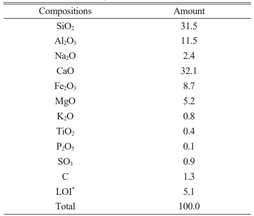
The chemical composition of the fly ash discharged from the CFBC boiler was analyzed by XRF shown in Table 1. The amount of SiO2 was low at 31.5 %, and the CaO content was very high at 32.1 %. Most of the CaO in the CFBC fly ash was in the free-CaO form; thus, stabilization of the fly ash into hydrated or carbonated form was done before use in the experiments. Hydration of fly ash was done with a water to fly ash ratio of 4 and a stirring speed of 500 rpm for 1 h. The carbonation of fly ash was done by injecting CO2 gas at 1000 cc/min for 2 h in a water vessel in which the water to fly ash ratio and the stirring speed were the same as the hydration process for the fly ash.
The 3 types of fly ashes, the original fly ash (denoted as O-FA), hydrated fly ash (denoted as H-FA) and carbonated fly ash (denoted as C-FA), were dried at 105 ℃ for 24 h and crushed to less than 150 mm before use. The chemical composition and identification of the crystal phases of the fly ashes were ascertained with XRF (ZSX-100e, Rigaku, Japan) and XRD (MiniFlexⅡ, Rigaku, Japan), respectively. Additionally, the particle size distribution was measured with a Sedigraph-5100 (Micromeritics Instrument Co., United States of America). In addition, the specific surface area of each fly ash was measured with the Blaine air-permeability apparatus (DY-101, Dyscale Co., Korea).
Granulation Process
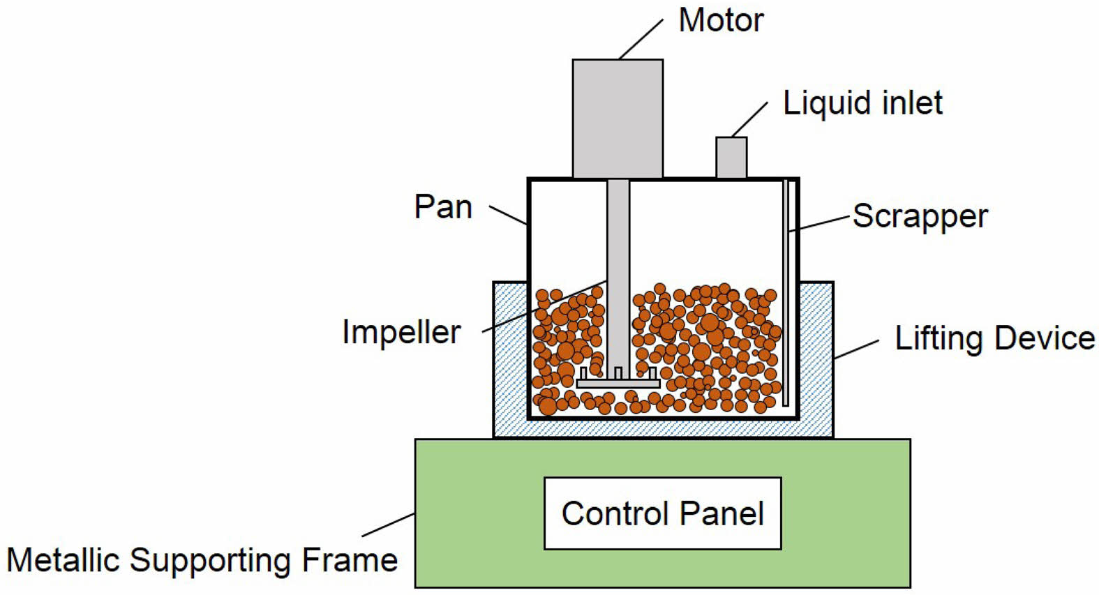
The granulation of fly ash in this study was done with a high intensive mixer (EL1, Maschinenfabik Gustav Eirich GmbH & Co KG, Germany) shown in Fig. 1. Water was poured through a liquid inlet into the barrel filled previously with an adequate amount of fly ash. The bottom pan plane can be titled against the stand. The rotating impeller delivers the shear stress to the powders while the rotational direction of the pan is reverse to that of the rotating impeller. From the preliminary tests for each fly ash, the liquid to solid ratios (denoted as L/S ratio) were found to be 0.26, 0.32, and 0.36 for O-FA, H-FA and C-FA, respectively. Those L/S ratios for each fly ash were fixed in this experiment. The impeller speed, pan speed, and pan tilting degree were also fixed at 2700 rpm, 85 rpm and 20°, respectively, throughout the experiment. The impeller design of the high intensive mixer uses the radial type.
The granules were sampled every 30 s until 3 min passed, and after that, they were sampled every 1 min. The sampled granules were dried at room temperature for 24 h, and their size distribution was measured with 7 sieves: 75 mm, 300 mm, 600 mm, 850 mm, 1.18 mm, 1.7 mm, and 2.36 mm meshes (TESTING SIEVE, Chung Gye Sang Gong Sa, Korea). Additionally, the morphology of the granules was observed with an optical camscope (DCS-105, Sometech-vision, Korea).
|
Fig. 1 The high intensive mixer for granulating the powder. |
Analysis of Raw Materials
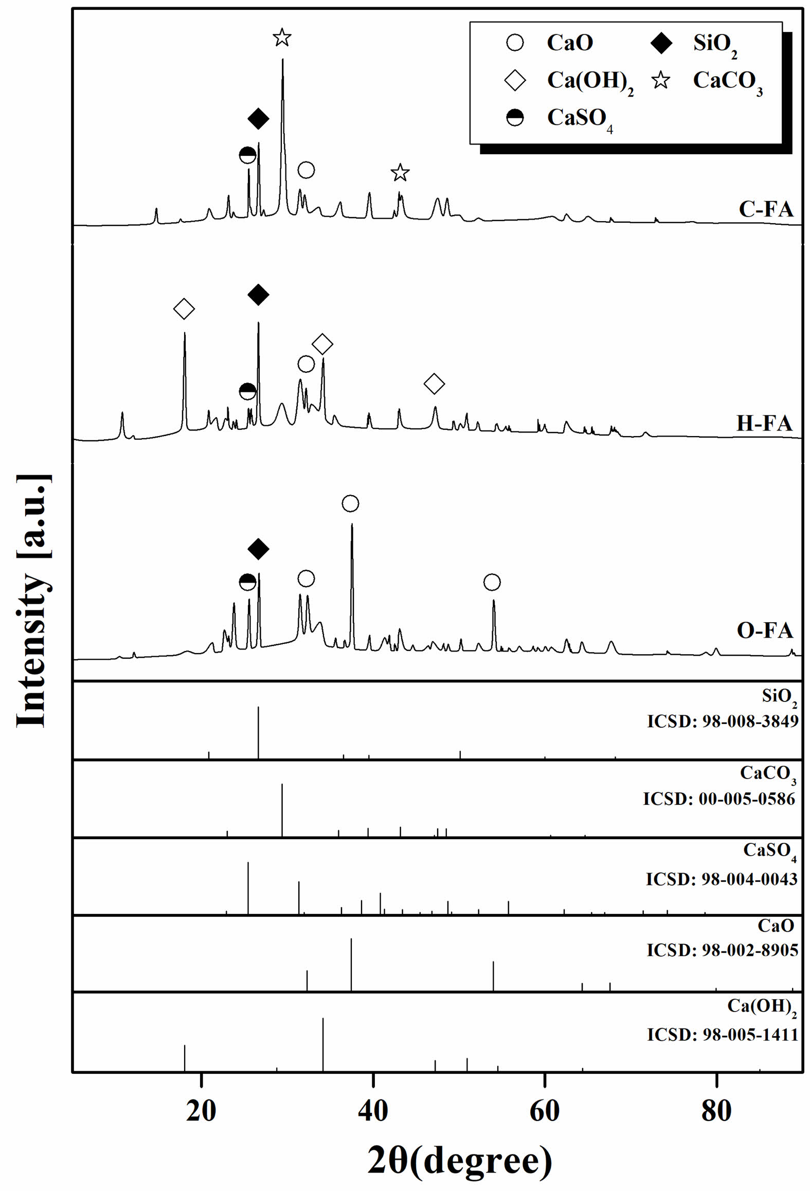
The XRD patterns of the 3 types of fly ashes are shown in Fig. 2. The major phase of the O-FA is CaO, while Ca(OH)2, and CaCO3 are the main phases in the H-FA and C-FA, respectively.
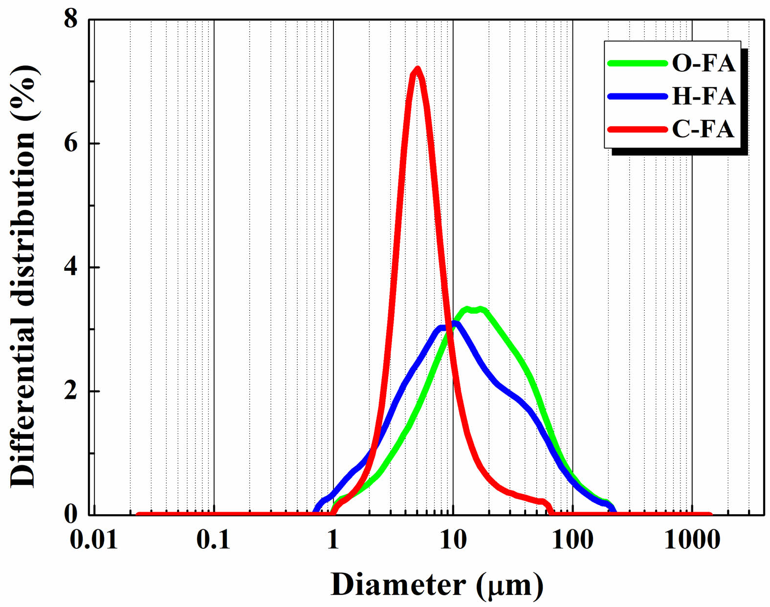
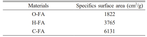
Fig. 3. shows the particle size distribution for the 3 types of fly ashes, C-FA (D10=2.75 μm, D50=5.04 μm, D90=12 μm), H-FA (D10=2.52 μm, D50=10.09 μm, D90=52.33 μm), and O-FA (D10=3.89 μm, D50=15.6 μm, D90=57.1 μm), with a median particle size of 5.0, 9.2 and 14.2 mm, respectively. The specific surface area of the C-FA is the highest at 6131 cm2/g while that for O-FA is the lowest at 1822 cm2/g, which is only 0.3 times that of the C-FA value presented in Table 2. The specific surface area of the H-FA is 3765 cm2/g, which is between the values for the C-FA and O-FA.
Shear stress vs. Time during granulation
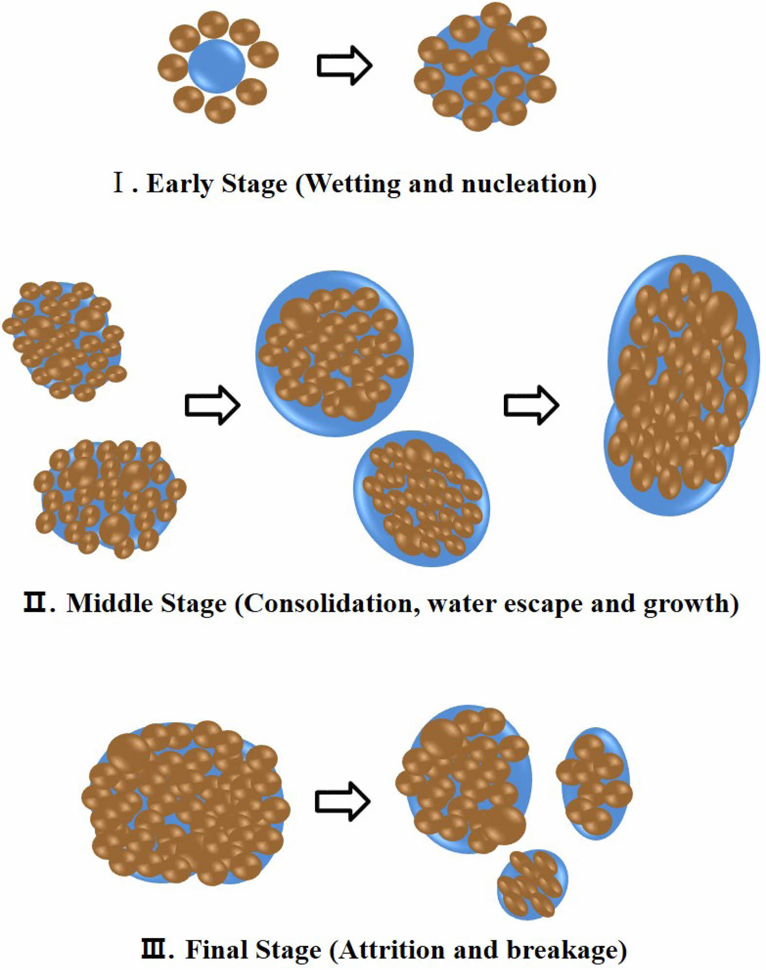
It is common to interpret the granulation process as a combination of three stages of the rate process. There is the early stage in which wetting and nucleation occur, the middle stage in which consolidation and growth of the granule proceed and the final stage in which attrition and breakage occur [26-28]. Generally, shear stress is low when the powder is dry. High shear stress occurs when the powder is sufficiently coagulated and shear stress is transmitted through the powder from the impeller. In the early stage of granulation, the shear stress increases rapidly as wetting and nucleation occur and then in the final stage, the shear stress decreases due to the dried granules [29, 30].
A schematic illustration of the three stages of granulation is shown in Fig. 4. In the early stage (I), the particles of the fly ash are wetted by water and agglomerated to form nuclei for granules. The fine particles require a longer time to wet due to a larger specific surface area in the early stage [31]. In the middle stage, the granules form and grow caused by collisions and coalescence between the nuclei. In addition, because the granules are plastically deformed and denser, the water is squeezed out from inside, which promotes the granules to consolidate and grow further [32]. In the final stage (Ⅲ), the water in the granules is almost evaporated, and the granules break by the attrition between the granules and/or the wall of the vessel.
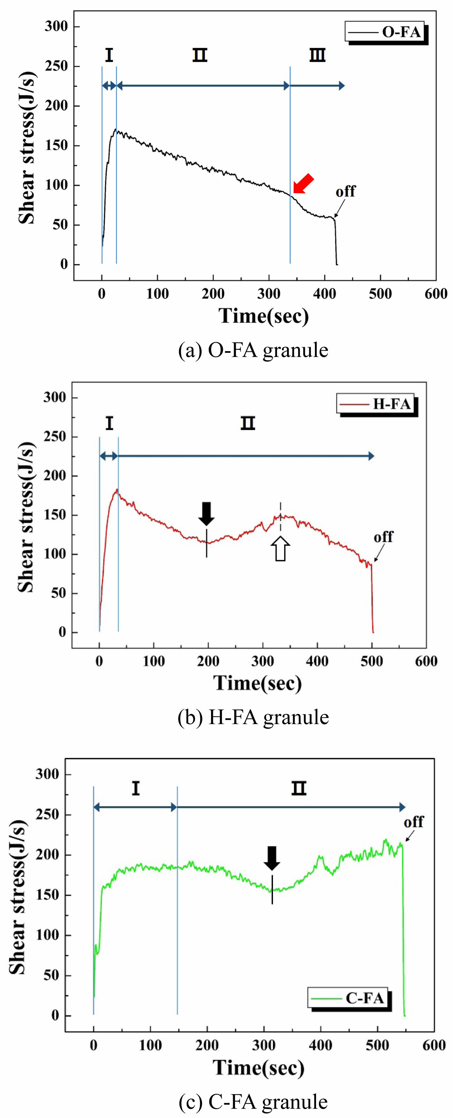
The variation in the shear stress acting on the impeller during the granulation process with the passing of time is shown in Fig. 5. First, in the case of O-FA, the shear stress increased rapidly within 0~25 s, indicating the early stage in which the particles of the fly ash are wetted by water and agglomerated to form nuclei. Then, the shear stress gradually reduces between 25~350 s, corresponding to the middle stage. The reason for this is the decreased specific surface area of the granules and the subsequent decreased contact with the impeller as the grains grow [33]. Then, the decreasing rate of the shear stress intensifies more after 340 s, during which time the dried granules break due to impact or attrition in the mixer, corresponding to the final stage [34].
For the granulation of H-FA, the early stage lasts for 0~35 s, which is a little bit longer than that of the O-FA due to the increased wetting time caused by the larger specific surface area and larger median particle size of the H-FA. In the middle stage, the granule grows at a constant rate; therefore, the specific surface area of the granule decreases, and the shear stress gradually decreases to a minimum value at 200 s (indicated by black arrow). After 200 s, the shear stress increases until 350 s.
The increase in shear stress at the halfway point in the middle stage is because the water is squeezed out of the granule from the inside. As collisions and coalescence between the granules proceed, plastic deformation and consolidation of the granules occur, making the granular structure dense [35, 36]. The water distributed over the surface of the granules forms a liquid bridge at contact points between the granules, and promotes the sticky action on the impeller increasing the shear stress [37]. From 350 s, the final stage begins, in which the granules dry and break due to attrition.
For C-FA granulation, the initial stage in which the shear stress increases is long compared to that of H-FA and O-FA, consisting of a rapid increase from 0~20 s and then, a gradual increase from 20~150 s. The longer early stage of the C-FA is because of the larger specific surface area requiring a longer time to wet the particles. As the granules grow, the shear stress gradually decreases up to 340 s, and then, the shear stress increases again (indicated by black arrow) because of the sticky surface caused by the water escaping out of the insides of the granules. The L/S ratio for the C-FA granulation was 0.36, which was the highest value among the 3 fly ashes because so much water escaped out of the granules in the middle stage. Consequently, the period during which the shear stress increased caused by the sticky surface lasted longer, and the granule size distribution began to widen because of the formation of large grains caused by the consolidation of sticky grains.
In the granulation of C-FA, the initial and middle stages are relatively long compared with those of O-FA and H-FA; thus, the final stage would appear later. In fact, the final stages for the granulation of C-FA did not appear from 0~550 s, which was the operating time for granulation in this experiment.
Size Distribution and Morphology of the Granules
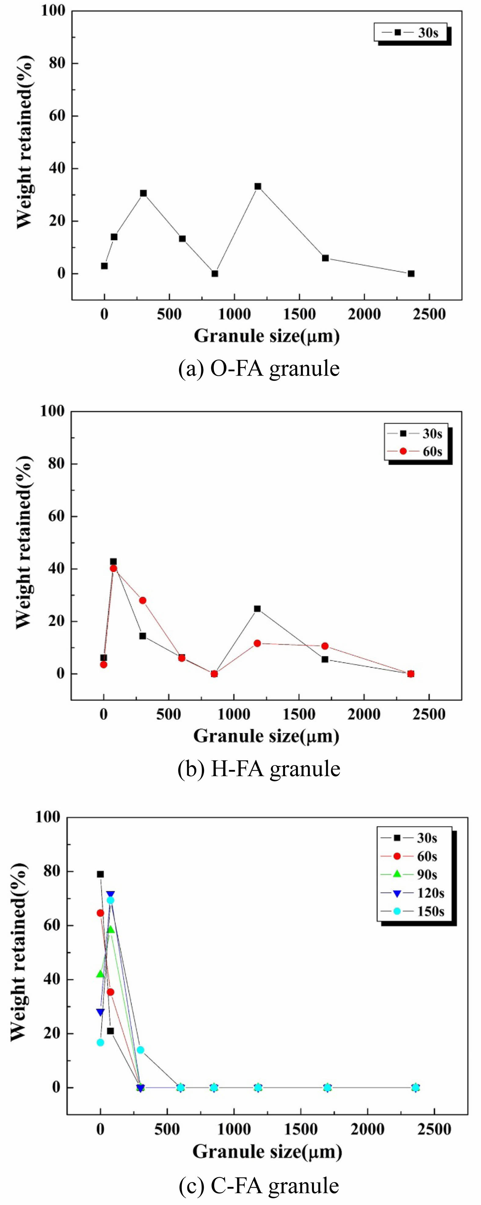
The granule size distribution in the early stage for the 3 kinds of fly ashes are shown Fig. 6. The early stage period for the C-FA was determined as 0~150 s from the time vs. shear stress graph shown in Fig. 5. The nuclei size was determined as 75 μm in this study because the main granule size was found to be 75 μm at the end of the early stage. For the initial stage of the H-FA granulation, its period was measured as 0~35 s from Fig. 5(c), and nuclei of 75 mm were mainly formed, and some larger granules of 1.18 mm were also generated. For the initial stage of the O-FA granulation, within 0~30 s, two main granules of 300 mm and 1.18 μm were generated as well as some small nuclei (75 μm). The reason for the occurrence of nuclei and growth simultaneously in the granulation of O-FA and H-FA is mainly because of the particle size of the starting materials. From Fig. 3, the O-FA and H-FA have some particles larger than 75 mm, defined as the nucleus size in this experiment.
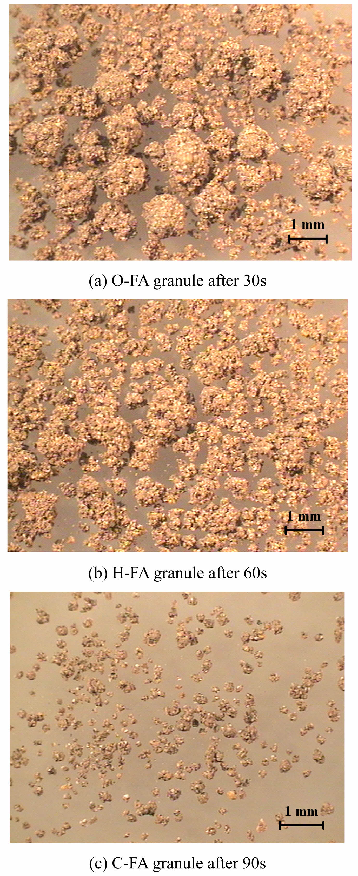
Optical microscopic images of the granules obtained in the early stage are shown in Fig. 7. Various sizes of granules containing larger granules over 1 mm as well as small nuclei were formed in the initial stage in O-FA and H-FA. In contrast, most of the particles obtained correspond to a nucleus size of 75 μm in the initial stage of C-FA.
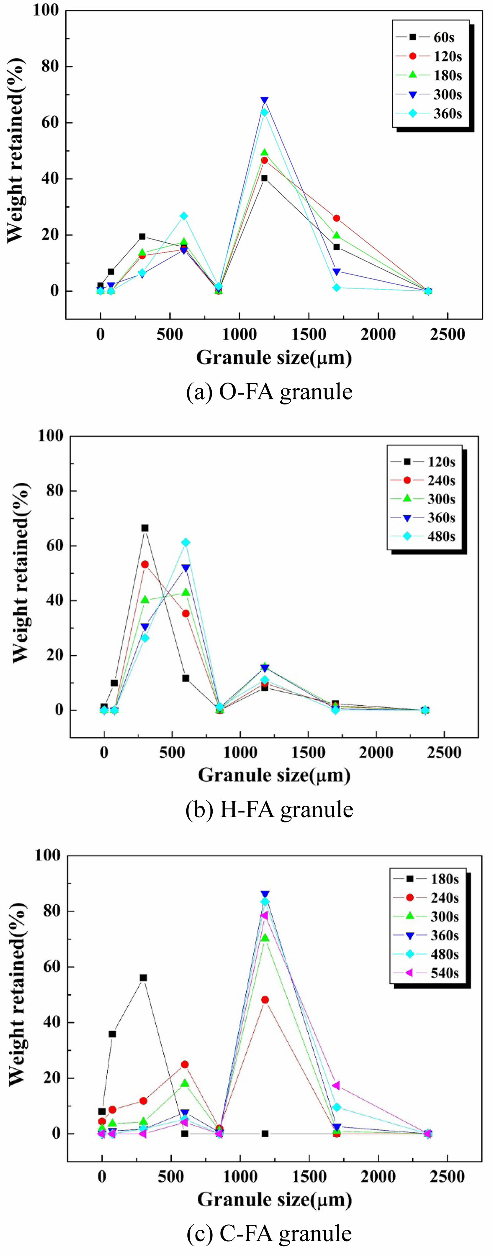
The granule size distribution graphs in the middle stage are shown in Fig. 8. For the granules from C-FA formed at 180 s, the peak intensity for the 75 μm nuclei decreased, and the peak for the 300 mm granules increased. Between 240~360 s, large granules of 1.18 mm were primarily formed while the second largest granules of 600 mm disappeared. When more time passed from 360 to 540 s, the newly-generated minor peak for the 1.7 mm granules slightly increases, while the major peak for the 1.18 mm granules somewhat decreases. This period of time corresponds to when the impeller shear stress increases indicated by the black arrow shown in Fig. 5(c). During that period, the squeezed-out water from the inside makes the granules sticky which accelerates the consolidation of the granules and their subsequent growth [38, 39]. To obtain a sharp granule size distribution with a mean diameter of 1.18 mm from the C-FA, the mixer operation should be terminated at around 360 s. The period of the initial state for H-FA granulation was measured as 35~350 s in Fig. 5(b). During the time that the shear stress increases in the middle stage, the granule size of the main peak moves from 300 mm to 600 mm for the H-FA shown in Fig. 8(b). During the middle stage of O-FA granulation, granules of 1.18 mm mainly formed as well as some granules of 600 mm and 1.7 mm, widening the size distribution graph.
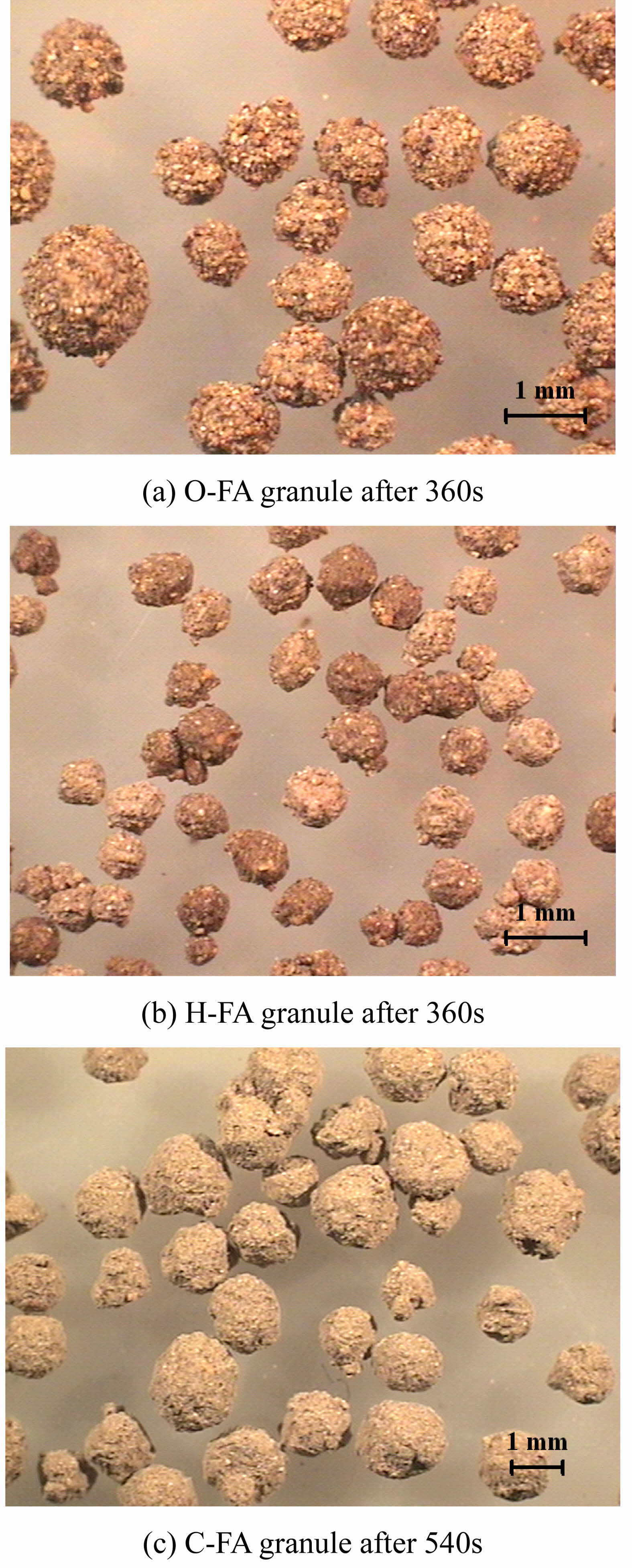
Only granules corresponding to the main peak in the granule size distribution graph obtained in the middle stage were selected and shown below in Fig. 9. The surface of granules from the O-FA is somewhat rough compared with that of the H-FA and C-FA, which could be because of the larger mean particle size of O-FA.
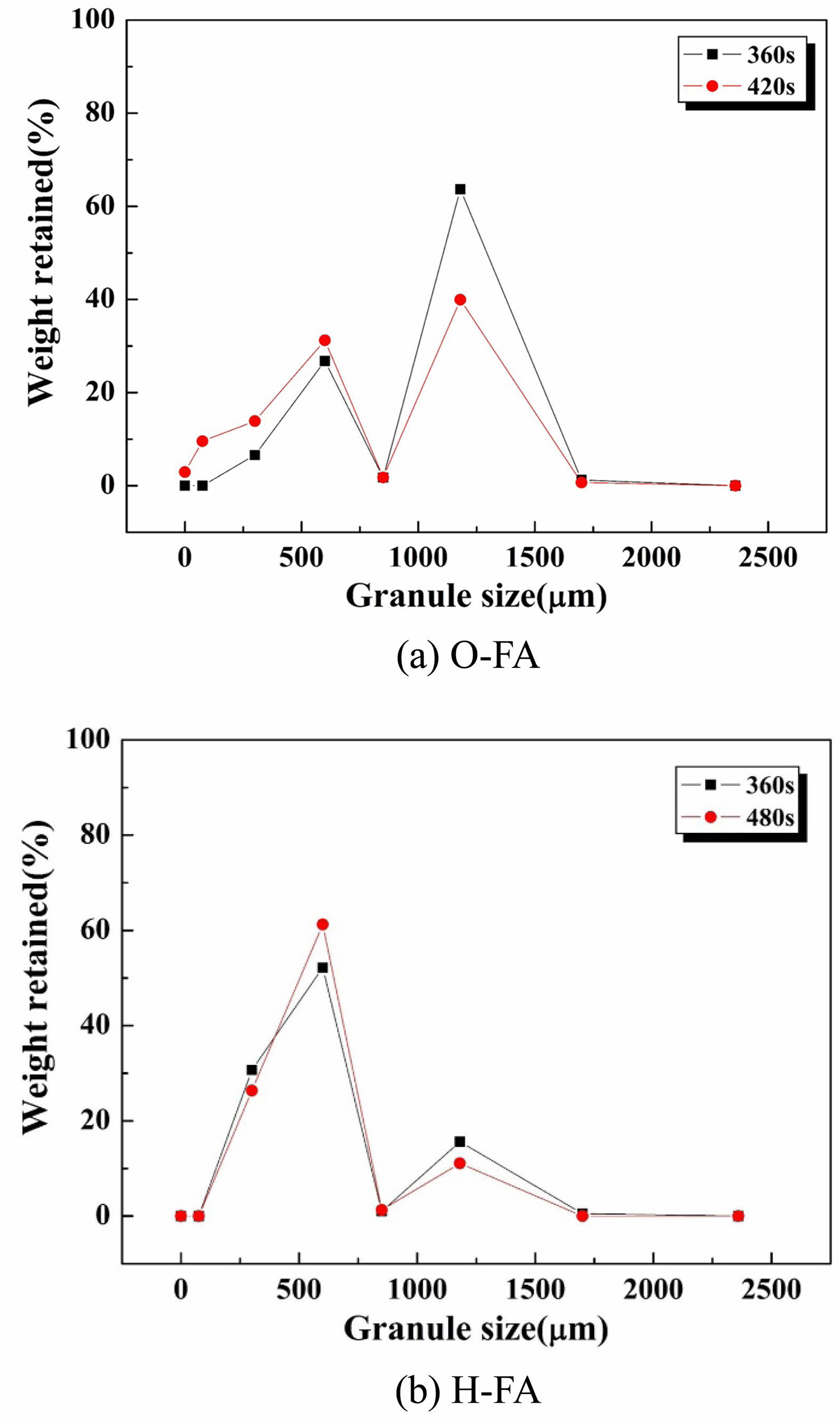
The granule size distribution at the final stage for O-FA and H-FA are shown in Fig. 10. After 360 s for O-FA granulation, the peak for granules of 1.18 mm decreased and the peak for granules of 600 mm increased slightly because the granules break because of attrition. This corresponds with where the shear stress suddenly decreases at 340 s shown in Fig. 5(a). During 360~480 s in the granulation of H-FA, the peak for the granules of 1.18 mm decreased slightly and the peak for the granules of 600 mm increased a little due to the attrition of the granules. H-FA and O-FA exhibited a final stage while C-FA did now show a final stage in the time range shown in Fig. 5, which is probably due to the high L/S ratio of 0.36 for the C-FA, suppressing the fast drying of the granules.
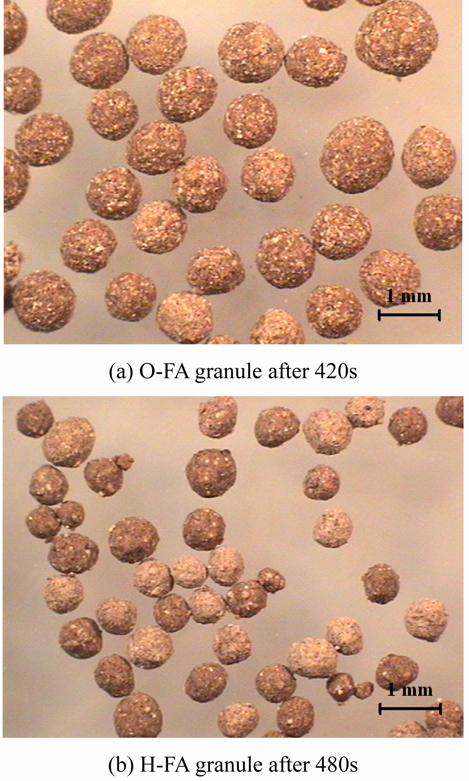
Only granules corresponding to the main peak in the granule size distribution graph obtained in the final stage were selected and shown in Fig. 11. The surface of the granules from O-FA is smooth compared to that obtained at the middle stage shown in Fig. 9(a). Moreover, the surface roughness of the granules for the H-FA smoothened compared to the surface obtained at the middle stage shown in Fig. 9 because of the attrition in the final stage. In the granulation of raw materials for ceramic using shear stress, particle size and shape affect plastic deformation and consolidation. Particles with small size and large specific surface area have improved adhesion and cohesion between particles due to wetting by liquid and plastic deformation under shear stress. Additionally, plastically deformed particles can be granulated through coagulation as continuous packing occurs [40].
|
Fig. 2 XRD pattern of the O-FA, H-FA and C-FA. |
|
Fig. 3 Particles size distribution of various fly ashes. |
|
Fig. 4 Schematic illustration of granulation process. |
|
Fig. 5 Shear stress acts on impeller as a function of time during granulation process. 3 steps of granulation are indicated; (Ⅰ) early stage, (Ⅱ) middle stage, and (Ⅲ) final stage. |
|
Fig. 6 Granule size distribution in the early stage by materials. |
|
Fig. 7 Morphology of the granules obtained in the early stage. |
|
Fig. 8 The granule size distribution at the middle stage. |
|
Fig. 9 Morphology of granules selected corresponding to the main peak in the granule size distribution graph at the middle stage. |
|
Fig. 10 Final stage of granule size distribution for (a) O-FA and (b) H-FA. |
|
Fig. 11 Morphology of selected granules corresponding to the main peak in the granule size distribution graph at the final stage. |
In this study, the granulation mechanisms for the various CFBC fly ashes, an original fly ash, a hydrated fly ash and a carbonated fly ash, were examined. Each fly ash with different physical properties showed different periods of time for each of the three stages in the granulation process. The granulation of fly ash with a high specific surface area (C-FA) had a long early stage of wetting and nucleation, while the O-FA and H-FA with a relatively lower specific surface area had a shorter early stage.
In the middle stage, the granules formed and grew caused by collisions and coalescence between nuclei, and the stress acting on the impeller decreased. As the granules grew, however, the granules plastically deformed and became denser; the water was squeezed out from the inside, and the stress increased again because of the sticky surface of the granules. That point in time did not appear in the granulation of O-FA with its coarse particles, in which a low L/S ratio is used.
In the granulation of the O-FA, having much free-CaO causing much heat of hydration, the granules quickly dried and were easily broken at the final stage due to attrition, which makes controlling the granulation of O-FA difficult; however, controlling the granule size and distribution are easy for the H-FA and C-FA. Consequently, granules of 600 mm~1.7 mm from CFBC fly ash could be fabricated with the desired width for the size distribution curve by controlling the operating time in the middle stage and modifying the fly ash, through hydration and carbonation.
This research was supported by Ceramic Strategy Technology Development Project (KPP24001) funded by Korea Institute of Ceramic Engineering and Technology.
The authors declare that they have no known competing financial interests or personal relationships that could have appeared to influence the work reported in this paper.
- 1. M.M. Aba, I.L. Sauer, and N.B. Amado, Int. J. Hydrogen Energy. 57 (2024) 660-678.
-

- 2. H.P. Kuo, H.Y. Tseng, A.N. Huang, and R.C. Hsu, Adv. Powder Technol. 25 (2014) 472-475.
-
- 3. H.Bilirgen, Fuel. 115 (2014) 618-624.
-
- 4. J. Wang, .K. Xu, Z. Li, Y. Yang, Q. Li, Y. Bao, H. Yang, L. ding, R. Zhang, Y. Wang, and L. Yao, J. Ceram. Process. Res. 23[1] (2022) 79-85.
-
- 5. E. Jeong, S. Jung, and H.S. Shin, Sci. Total Environ. 945 (2024) 174104.
-
- 6. J. Park and Y.T. Kim, J. Ceram. Process. Res. 15[4] (2014) 212-215.
-
- 7. Y. Kim, Y. Ryu, H. Jeon, G.K. Lee, S. Kang, J. Kim, C.S. Jang, and S.G. Lee, J. Ceram. Process. Res. 11[2] (2010) 225-232.
-
- 8. G. Sheng, J. Zhai, Q. Li, and F. Li, Fuel. 86 (2007) 2625-2631.
-
- 9. C. Chinnaraj, K. Subramanian, and P. Muthupriya, J. Ceram. Process. Res. 25[3] (2024) 345-354.
-
- 10. C. Baek, J. Seo, M. Choi, J. Cho, J. Ahn, and K. Cho, Sustainability. 10 (2018) 4854.
-
- 11. S.E. Lee and Y.C. Choi, Const. Build. Mater. 439 (2024) 137273.
-
- 12. X.Y. Wang, J. Ceram. Process. Res. 21[6] (2020) 622-631.
-
- 13. S.K. Seo, J. Ceram. Process. Res. 18[3] (2017) 177-182.
-
- 14. J.S. Sim, K.G. Lee, Y.T. Kim, and S.K. Kang, J. Korean Ceram. Soc. 49 (2012) 185-190.
-
- 15. J.S. Sim, K.G. Lee, Y.T. Kim, and S.K. Kang, J. Korean Ceram. Soc. 50 (2013) 18-24.
-
- 16. P.B. Pathare, N. Bas, J.J. Fitzpatrick, K. Cronin, and E.P. Byme, Biosyst. Eng. 110 (2011) 473-481.
-
- 17. P. Pandey, J. Tao, R. Chaudhury, J.Z. Gao, and D.S. Bindra, Pharm. Dev. Technol. 18 (2013) 210-224.
-
- 18. S.M. Iveson, J.D. Litster, K. Hapgood, and B.J. Ennis, Powder Technol. 117 (2001) 3-39.
-
- 19. P.K. Le, P. Avontuur, M.J. Hounslow, and A.D.Salman, Powder Technol. 189 (2009) 149-157.
-
- 20. Y. Liu, D. Scharf, T. Graule, and F.J. Clemens, Powder Technol. 263 (2014) 159-167.
-
- 21. T.M. Chitu, D. Oulahna, and M. Hemati, Powder Technol. 206 (2011) 34-43.
-
- 22. W.D. Tu, A. Ingram, J. Seville, and S.S.Hsiau, Chem. Eng. J. 145 (2009) 505-513.
-
- 23. H.J. Cheng, S.S. Hsiau, and C.C. Liao, Powder Technol. 211 (2011) 165-175.
-
- 24. P.C. Knight, A. Johansen, H.G. Kristensen, T. Schæfer, and J.P.K. Seville, Powder Technol. 110 (2000) 204-209.
-
- 25. S.H. Cho, S.M. Joo, J.S. Cho, J.K. Lee, and H. Kim, J. Ceram. Process. Res. 6[1] (2005) 57-62.
- 26. B.J. Ennis and J.D. Litster, in “Particle size enlargement” (Perry’s Chemical Engineers’ Handbook, 7th end., 1997), pp. 20-56-20-89.
- 27. P. Mort and G. Tardos, Kona. 17 (1999) 64-75.
-
- 28. M. Butensky and D. Hyman, Ind. Eng. Chem. Fundam. 10 (1971) 212-219.
-
- 29. G.I. Tardos, K.P. Hapgood, O.O. Ipadeola, and J.N. Michaels, Powder Technol. 140[3] (2004) 217-227.
-
- 30. A. Szulc, E. Skotnicka, M.K. Gupta, and J.B. Królczyk, Powder Technol. 431 (2024) 119092.
-
- 31. L. Kotamarthy, A. Dan, S. Karkala, S. Parvani, A.D. Román-Ospino, and R. Ramachandran, Adv. Powder Technol. 34 (2023) 104137.
-
- 32. I. Muthancheri, A. Chaturbedi, A. Bétard, and R. Ramachandran, Adv. Powder Technol. 32 (2021) 2085-2096.
-
- 33. V. Boonkanokwong, R.P. Frank, P. Valliappan, B. Remy, J.G. Khinast, and B.J. Glasser, Adv. Powder Technol. 29 (2018) 2733-2752.
-
- 34. B. Liu, J. Wang, Q. Zhou, L. Zhao, Y. Wang, L. Shen, and R. Du, Adv. Powder Technol. 33 (2022) 103369.
-
- 35. H.J. Cheng and S.S. Hsiau, Powder Technol. 199 (2010) 272-283.
-
- 36. M. Bardin, P.C. Knight, and J.P.K. Seville, Powder Technol. 140[3] (2004) 169-175.
-
- 37. T. Kusano, M. Yokota, A. Yonaga, Y. Akimoto, M. Tani, H. Nakamura, and T. Matsunaga, Adv. Powder Technol. 33 (2022) 103585.
-
- 38. S. Pohl and P. Kleinebudde, Int. J. Pharm. 587 (2020) 119660.
-
- 39. K.V. Probst and K.E. Ileleji, Adv. Powder Technol. 27 (2016) 1347-1359.
-
- 40. J.B. Wade, G.P. Martin, and D.F. Long, Int. J. Pharm. 478[2] (2015) 439-446.
-
 This Article
-
2025; 26(1): 58-65
Published on Feb 28, 2025
- 10.36410/jcpr.2025.26.1.58
- Received on Sep 20, 2024
- Revised on Oct 30, 2024
- Accepted on Jan 10, 2025
Services
- Abstract
introduction
experimental procedure
results and discussion
conclusions
- Acknowledgements
- Conflict of Interest
- References
- Full Text PDF
Shared
Correspondence to
- Kangduk Kim
-
Department of Advanced Material Engineering, Kyonggi University, Suwon 16227, Korea
Tel : +82-10-6206-6290 - E-mail: solidwaste@kyonggi.ac.kr
Clean-Energy Research Institute(CRI), Hanyang University, 222, Wangsimni-ro, Seongdong-gu, Seoul, 04763, Korea
E-mail: jcpr@hanyang.ac.kr