- Tribological behavior of AA7075 hybrid composites reinforced with Al2O3 and TiO2 particles
N.H. Agilandeswaria,*, J. Jebeen Mosesb, M. Felix Xavier Muthuc and T CH Anil Kumard
aAssistant Professor, Department of Civil Engineering, E.G.S. Pillay Engineering College, Nagappattinam 611002, Tamilnadu, India
bAssociate Professor, Department of Mechanical Engineering St. Xavier’s Catholic College of Engineering Chunkankadai, Nagercoil, Tamil Nadu, India
cAssociate Professor, Department of Mechanical Engineering St. Xavier’s Catholic College of Engineering Chunkankadai, Nagercoil, Tamil Nadu, India
dAssistant Professor, Department of Mechanical Engineering, Vignan’s Foundation for Science Technology and Research, Vadlamudi, Guntur Dt., Andhra Pradesh, IndiaThis article is an open access article distributed under the terms of the Creative Commons Attribution Non-Commercial License (http://creativecommons.org/licenses/by-nc/4.0) which permits unrestricted non-commercial use, distribution, and reproduction in any medium, provided the original work is properly cited.
The study investigates the wear behavior of AA7075 hybrid composites reinforced with varying percentages of Al2O3 and TiO2. The microstructure reveals a homogenous distribution of reinforcing particles in the aluminum alloy matrix, enhanced by the addition of K2TiF6 flux. The wear process parameters, including % reinforcement, applied load, temperature, sliding velocity, and sliding distance, are systematically studied to understand their effects on wear resistance. The results reveal a non-linear trend in wear rate with increasing % reinforcement, showing an optimal percentage for the lowest wear rate. Applied load initially improves wear resistance but can lead to increased wear rates beyond threshold limit. The wear rate decreases initially with increasing temperature, indicating improved wear resistance, but increased at higher temperatures due to thermal softening effects. Sliding velocity and distance also significantly influence wear behavior, with lower wear rates observed at moderate velocities and distances due to the formation of protective layers. The addition of reinforcement reduces the COF, the relationship between COF and wear rate is inversely proportional, with lower COF leading to lower wear rates. The presence of reinforcement stabilizes the COF at different sliding distances, indicating improved wear resistance. The worn surface morphology indicates severe abrasion, micro-cutting, and plastic deformation, influenced by particle characteristics and load.
Keywords: Tribology, Friction, Surface morphology, Hybrid composites, Wear mechanisms.
Aluminium matrix composites (AMCs) gaining importance due to their lightweight and excellent mechanical characteristics, making them suitable for a variety of applications. Hybrid composites, which are made by mixing various reinforcing materials, have the potential to improve the characteristics of AMCs [1, 2]. The wear behavior of these hybrid composites influenced by various factors, including the type and content of reinforcement materials, the matrix material, and the manufacturing process [3]. The wear process parameters, such as applied load, sliding speed, and sliding distance, plays a critical role in determining the wear behavior of hybrid composites [4, 5]. Increased applied load typically results in an increase in wear rate. Al7075-based hybrid composites reinforced with SiC and Al2O3 showed that increasing the weight proportion of reinforcement increased wear resistance, with greater applied loads resulting in lower wear rates [6]. This behavior can be due to greater contact pressure and energy dissipation at higher loads, which causes more severe wear [7]. Augmented sliding speed increase wear rate owing to increased energy input and temperature increases at higher speeds. In magnesium-SiC-Gr hybrid composites, increasing the sliding speed resulted in increased wear rates, which were ascribed to the higher temperatures generated at higher speeds, which can accelerate wear processes such as abrasion and adhesion [8].
Increased sliding distance can cause an increase in wear rate, owing to the accumulation of wear debris and changes in contact conditions over time. AMCs reinforced with SiC and Al2O3 reported that the 15% hybrid composite exhibited superior wear resistance compared to the 5% composite which revealed that the type and concentration of reinforcement material can significantly influence wear properties [9]. Al7150-hBN nanocomposites found that the wear resistance of the material decreased at higher temperatures, attributed to the softening of the matrix material and the degradation of the hBN reinforcement [10]. Despite extensive research on hybrid composite wear behaviour, there is a lack of comprehensive studies that investigate the combined effects of multiple process parameters, such as percentage reinforcement, applied load, temperature, sliding velocity, and sliding distance, on the wear behaviour of AA7075-based hybrid composites reinforced with Al2O3 and TiO2. The objective of this study is to examine the wear behaviour of AA7075-based hybrid composites reinforced with Al2O3 and TiO2 under various process conditions. The objective of this research is to find the best combination of these parameters to improve wear resistance.
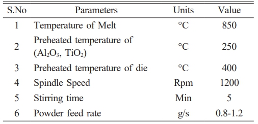
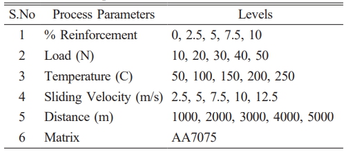
The process begins with the preparation of the matrix alloy, which involves placing around 1kg of the aluminium alloy AA7075 in a graphite crucible and heating it to around 850 °C with an electric stir casting furnace. The Al2O3 and TiO2 reinforcing particles are heated to 250 °C for an hour to eliminate moisture. Aluminium requires a temperature of around 1100 °C to thoroughly wet Al2O3 and TiO2, a flux such as potassium hexafluorotitanate (K2TiF6) is used to improve wettability. This flux combines with aluminium to generate titanium, which covers the reinforcing particles and strengthens the link between the matrix and reinforcement. The heated Al2O3 and TiO2 particles, covered in aluminium foil, are added to the molten alloy. The mixture is then mechanically agitated at 750 rpm for 2 minutes. After that, the flux is added to the melt and the mixture is agitated for another 3 minutes. The melt is then poured into mild steel permanent moulds at 400 °C to create specimens with the specified dimensions. After casting, the specimens are machined to remove surface imperfections and cut to the appropriate proportions for wear testing. The stir casting process parameter was shown in Table 1. Table 2
The wear test samples were prepared in accordance with ASTM G99-05 standards. The wear test was conducted using a 100 mm wear track diameter. During the wear test, each sample’s maximum frictional force was determined using a computerised tribometer. Prior to and during wear testing, the samples were weighed using an electronic weighing device with a 0.0001 g precision.
Microstructure of AA7075 hybrid composites
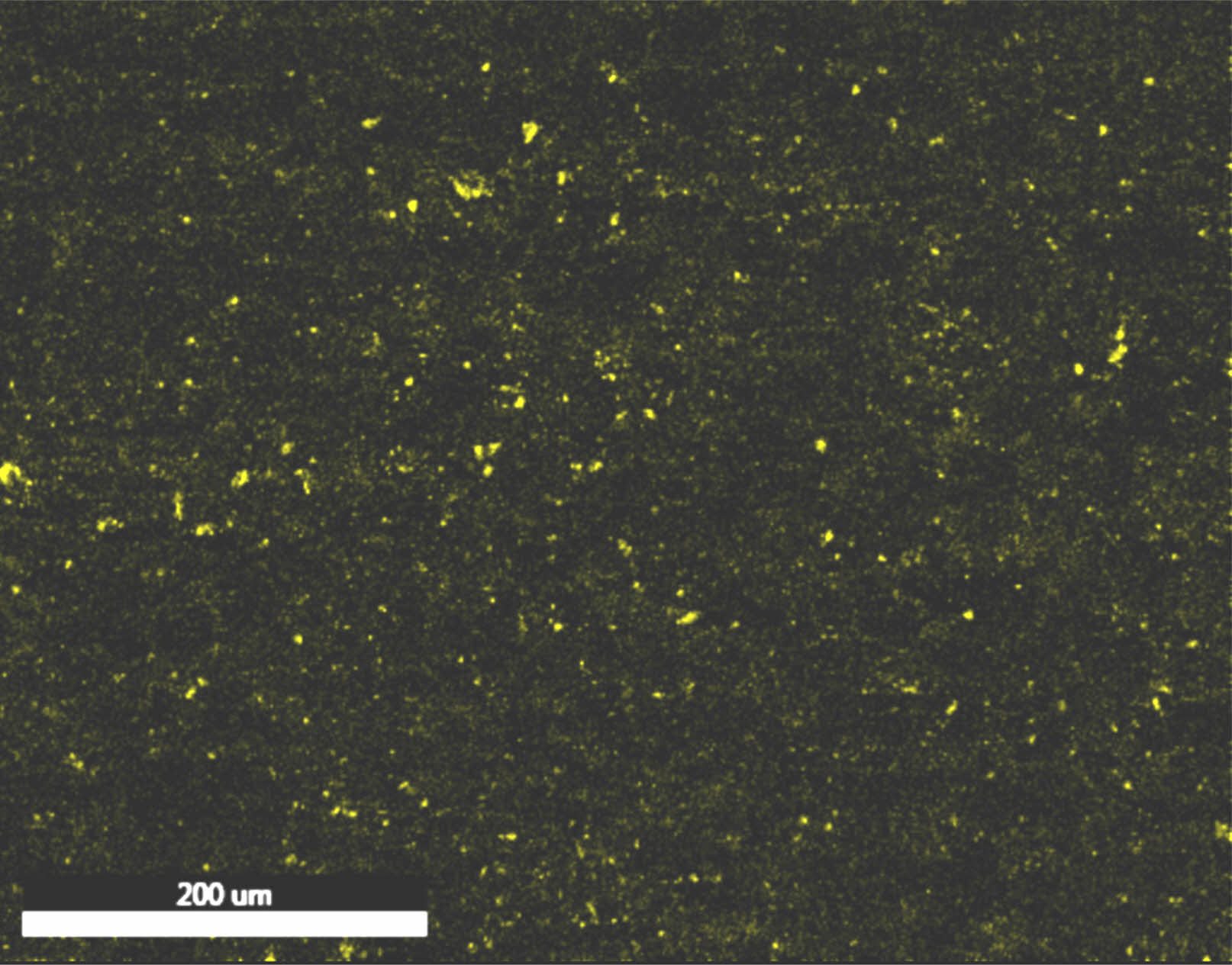
Figure 1 showed the scanning electron micrographs of AA7075 hybrid composites. The microstructures of the composites clearly show the homogenous distribution of reinforcing particles in the Al alloy matrix. The addition of K2TiF6 flux enhances the bonding between matrix and reinforcement. Because of the interaction between the flux and the molten aluminium alloy, titanium in the flux surrounds the reinforcing particles, increasing wettability. Because of this reaction, no intermetallic compounds were produced [11].
Wear behavior of AA7075 hybrid composites
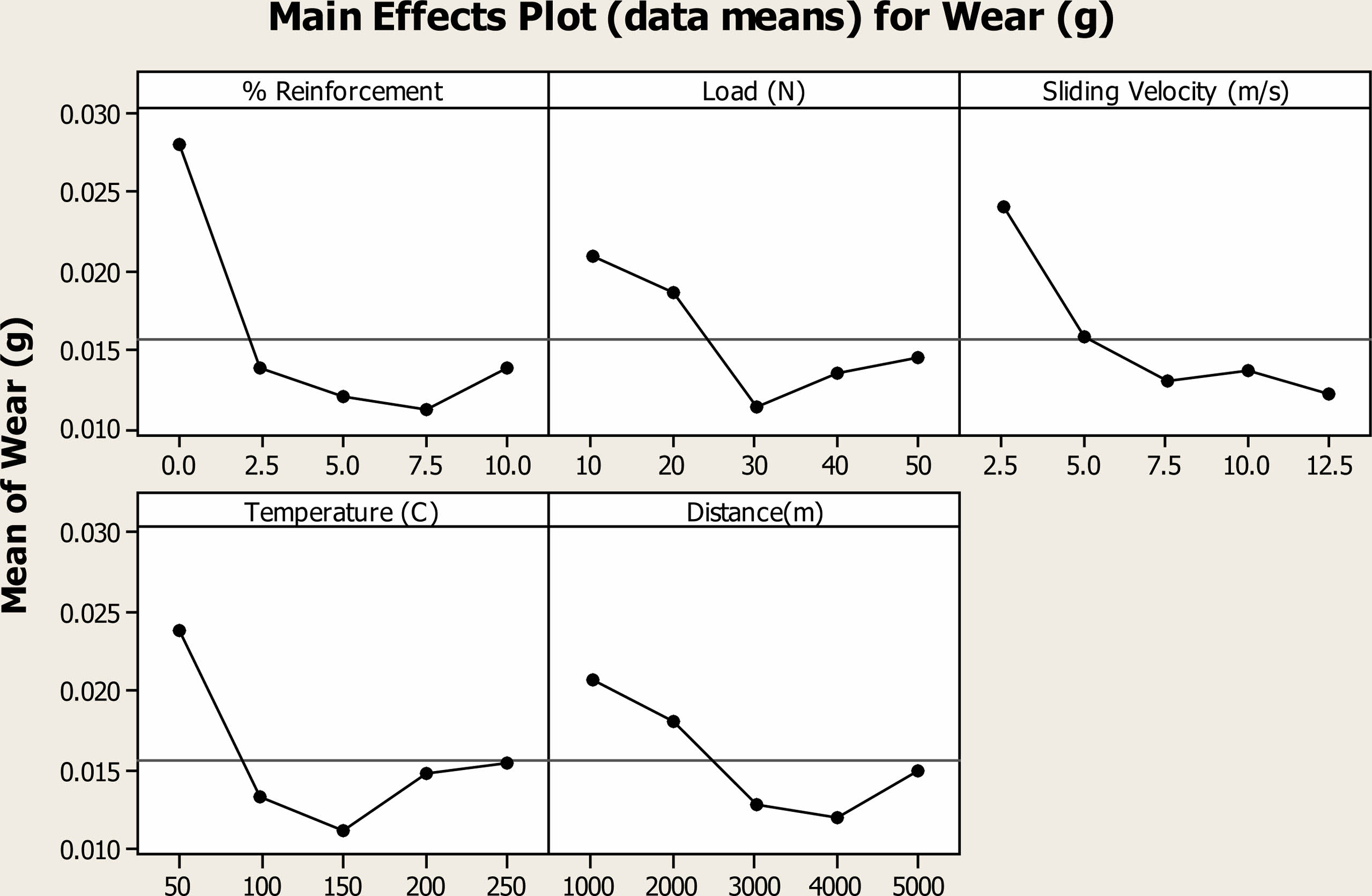
The percentage of reinforcement increased from 0% to 10%, the wear rate exhibited a non-linear trend, with the lowest wear rate observed at 7.5% reinforcement. Specifically, the wear rate decreased from 0.027 g for the unreinforced composite to 0.0110 g for the composite containing 7.5% reinforcement as shown in Fig. 2. This reduction in wear rate can be attributed to the presence of the reinforcing particles, which act as obstacles to prevent direct contact between the mating surfaces, reducing abrasion. However, a slight increase in wear rate was observed for the composite containing 10% reinforcement, indicating a possible saturation effect or a change in the wear mechanism at higher reinforcement percentages. This non-linear behavior suggests that the addition of TiO2 and Al2O3 reinforcements can improve the wear resistance of AA7075 composites, but an optimal reinforcement percentage exists for achieving the lowest wear rate. The observed trend in wear rate can be explained by considering the formation of a mechanical mixed layer during sliding. At lower reinforcement percentages, the abrasive particles contribute to the formation of a compacted and work-hardened layer on the surface, which acts as a protective barrier against further wear. This layer, known as the mechanical mixed layer, effectively reduces the wear rate [12]. At 7.5% reinforcement, the formation of the Mechanical Mixed Layer (MML) due to third body abrasion acts as a barrier, preventing direct metal contact and reducing wear rate. However, at 10% reinforcement, particle agglomeration occurs, leading to uneven distribution and clustering of particles. This agglomeration induces abrasive wear, which diminishes the beneficial effects of reinforcement, ultimately resulting in a slight increase in the wear rate compared to the 7.5% reinforcement level.
The results indicated that as the load increased from 10N to 30N, there was a significant decrease in wear rate, suggesting improved wear resistance. This reduction in wear rate can be attributed to the increased contact pressure between the mating surfaces, which enhances the formation of a MML and promotes plastic deformation, reducing wear. However, a slight increase in wear rate was observed at 40N and 50N, indicating that beyond a certain threshold, the increased load lead to more severe abrasive wear or deformation mechanisms that outweigh the benefits of increased contact pressure. Increased contact pressure enhances the formation of the MML during sliding, which plays a crucial role in improving wear resistance under higher loads. The MML acts as a protective barrier between mating surfaces, reducing direct metal-to-metal contact and minimizing material loss due to abrasion. Additionally, higher contact pressure promotes better interfacial adhesion and mechanical interlocking between the sliding surfaces, further reinforcing the MML and enhancing its effectiveness in mitigating wear. The observed trend in wear rate with increasing load can be explained by considering the competing effects of load on wear behavior. At lower loads, the abrasive particles on the mating surfaces can cause more severe wear due to insufficient contact pressure to promote MML. As the load increases, the contact pressure enhances the formation of a MML and promotes plastic deformation, reducing wear. However, at higher loads, the abrasive wear become more dominant, leading to increased wear rates.
The results showed that the wear rate decreased initially from 0.0237 g at 50 °C to 0.011 g at 150 °C, indicating improved wear resistance with increasing temperature. This decrease in wear rate can be attributed to the increased thermal activation of atoms at higher temperatures, leading to enhanced plastic deformation and reduced adhesion between the mating surfaces [13]. However, a slight increase in wear rate was observed at 200 °C and 250 °C, suggesting that beyond a certain temperature, the thermal softening of the material lead to increased wear due to more severe deformation mechanisms. The observed trend in wear rate with increasing temperature highlights the complex interplay between temperature, material properties, and wear mechanisms. At lower temperatures, the material exhibit higher hardness and stiffness, leading to increased wear resistance. As the temperature increases, the material becomes more ductile and able to deform plastically, reducing wear. However, at higher temperatures, the material undergo thermal softening, reducing its ability to resist wear and leading to increased wear rates. These findings suggest that the optimal temperature for minimizing wear rate lies within the range of 100 °C to 150 °C for AA7075 hybrid composites.
Wear rate decreased initially from 0.0240 g at 2.5 m/s to 0.0121 g at 12.5 m/s, indicating improved wear resistance with increasing sliding velocity. This decrease in wear rate can be attributed to the increased strain rate and deformation of the material at higher sliding velocities, which leads to enhanced surface hardness and resistance to wear. The observed trend in wear rate with sliding velocity suggests that the sliding velocity has a significant impact on the wear behavior of AA7075 hybrid composites [14]. At lower sliding velocities, the material experience lower deformation and strain rates, leading to higher wear rates. As the sliding velocity increases, the material undergoes more severe deformation, which can result in the formation of a protective transfer layer on the surface, reducing wear. The wear rate decreased initially from 0.020 g at 1000 m to 0.0120 g at 4000 m, indicating improved wear resistance with increasing sliding distance. However, a slight increase in wear rate to 0.0148 g was observed at 5000 m. The decrease in wear rate with sliding distance can be attributed to the development of a stable and protective tribo layer on the surface of the composites over time. As the sliding distance increases, the contact surfaces undergo more severe deformation and interaction, leading to the formation of a compacted layer of wear debris and oxide particles. This layer acts as a barrier, reducing the direct contact between the mating surfaces and thereby decreasing the wear rate. The increase in wear rate at 5000 m can be attributed to accumulation of wear debris and third-body abrasives on the contact surfaces over prolonged sliding, leading to increased abrasive wear. As sliding velocity and distance increase, wear debris generation also rises, which can act as a protecting layer, reducing direct contact and friction between mating surfaces. This phenomenon leads to a decrease in wear rate, as observed. However, at extended sliding distances of 5000 m, wear debris accumulation reach a critical point where it starts to exacerbate wear. Excessive debris accumulation can lead to abrasive wear, where hard particles trapped between surfaces cause more material removal. In addition, agglomerated wear debris can act as abrasives themselves, intensifying the wear process.
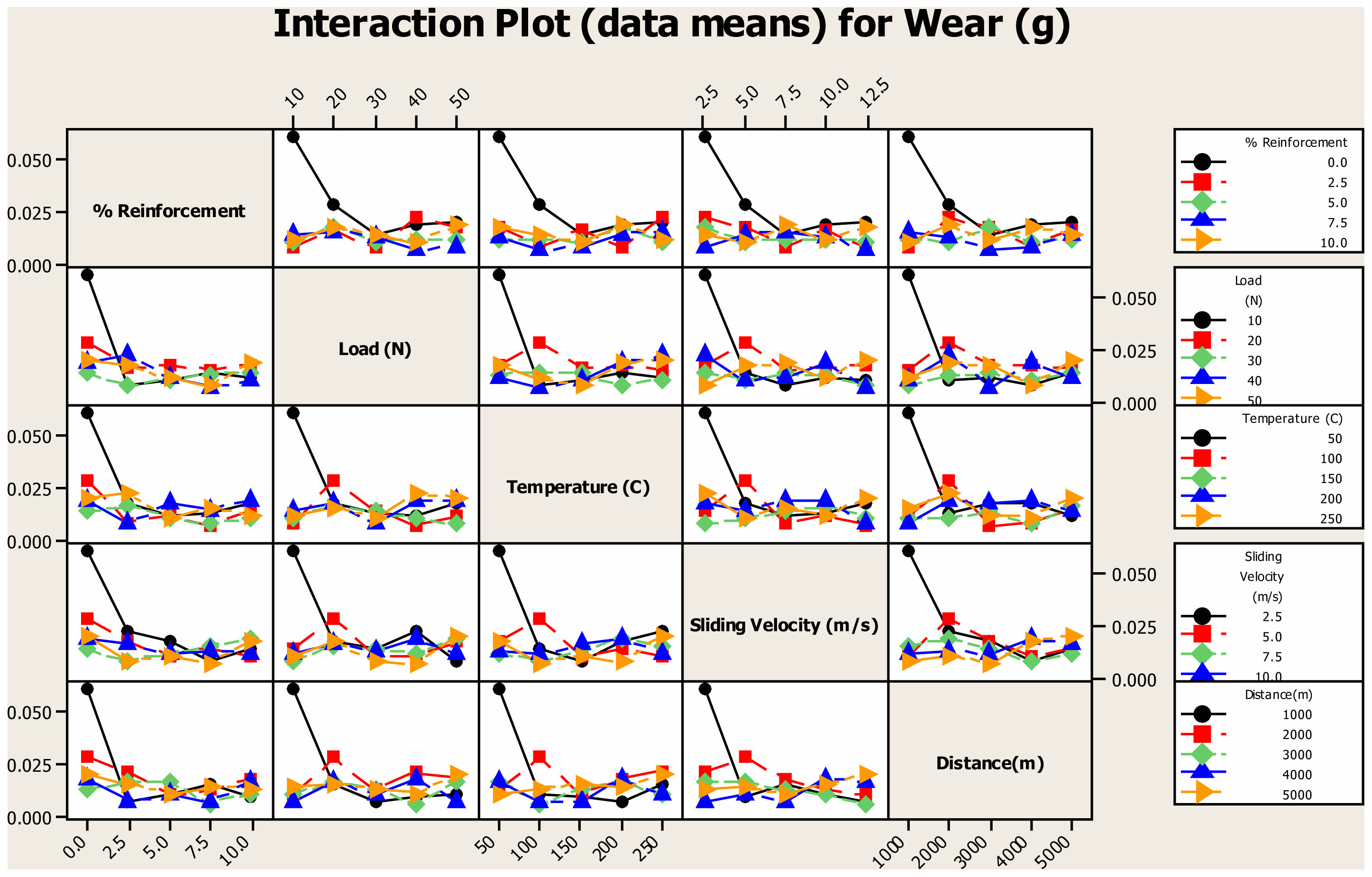
The interaction plot for distinct parameter which impact wear rate was depicted in the Fig. 3. The plot reveals distinct regions of wear behavior based on the sliding distance and velocity. For wear less than 0.003 g, the optimal range is observed between 2250-3500 m of sliding distance and 8-12 m/s of sliding velocity. In this range, the wear rate is significantly low, indicating that the composites exhibit excellent wear resistance under these conditions [15]. This finding suggests that the composites perform best at moderate sliding distances and velocities, where the formation of a protective tribolayer is most effective. For wear between 0.003 and 0.006 g, two distinct regions are identified: one between 1750-2250 m and another between 3500-4000 m of sliding distance. In both regions, the sliding velocity ranges from 5.5 to 8 m/s. This suggests that the wear rate increases slightly in these regions compared to the optimal range, indicating a moderate wear behavior. The higher wear rate in these regions could be attributed to increased contact stresses and deformation at the surfaces. For wear higher than 0.018 g, the extremes of the sliding distance (1000 m and 5000 m) and a sliding velocity of 3 m/s result in the highest wear rates. This observation indicates that the composites experience severe wear at low sliding velocities and at the beginning and end of the sliding distance range.
The plot reveals distinct regions of wear behavior based on the sliding distance and temperature. For wear lesser than 0.004 g, the optimal condition is observed at a distance of 3000 m and a temperature of 150 °C. In this region, the wear rate is significantly low, indicating that the composites exhibit excellent wear resistance under these specific temperature and distance conditions. This finding suggests that the temperature of 150 °C plays a crucial role in enhancing the tribological performance of the composites at the specified distance [16]. Conversely, for wear higher than 0.016 g, two distinct regions are identified: one at a distance of 1000 m and a temperature of 50 °C, and another at a distance of 5000 m and a temperature of 250 °C. In both regions, the wear rates are significantly higher compared to the optimal condition. This observation suggests that extreme temperature conditions, either low (50 °C) or high (250 °C), coupled with specific sliding distances, result in increased wear rates for the composites.
These regions indicate that at low sliding velocities and extreme temperature conditions, the wear rates of the composites are significantly higher. This observation suggests that the combination of low sliding velocity and either low or high temperature leads to increased wear rates for the composites. for low wear rates (0.0019 g), a region is identified at a temperature of 150 °C and a sliding velocity of 10 m/s. In this region, the wear rate is significantly low, indicating that the composites exhibit excellent wear resistance under these specific temperature and sliding velocity conditions [17]. This region indicates that under low load and shorter sliding distances, the wear rates of the composites are significantly higher. This observation suggests that the combination of low load and shorter sliding distances leads to increased wear rates for the composites. Conversely, for low wear rates (0.00282 g), a region is identified at a load of 40 N and a distance of 3000 m. In this region, the wear rate is significantly low, indicating that the composites exhibit excellent wear resistance under these specific loads and sliding distance conditions. This finding suggests that higher loads and longer sliding distances play crucial roles in reducing the wear rates of the composites.
High wear rates was obtained for the parametric value of 10 N and 50 °C. It indicates that under low load and moderate temperatures, the wear rates of the composites are significantly higher. The observation suggested that the combination of low load and moderate temperatures leads to increased wear rates for the composites. As the temperature increases to 250 °C, the wear rate also increases to 0.0134 g for the same load of 10 N suggested that higher temperatures exacerbate the wear behavior of the composites, leading to higher wear rates. The minimum wear rate (0.00291 g), was obtained for the parametric value of 35 N and 150 °C. The region that the low distance with unreinforced alloy, the wear rates of the composites are significantly higher [18]. The observation suggests that the combination of low distance and absence of reinforcement leads to increased wear rates for the composites. As the percentage of reinforcement increases to 7.5%, the wear rate also increases to 0.032 g for the same distance of 1000 m. This suggests that higher reinforcement percentages exacerbate the wear behavior of the composites, leading to higher wear rates. The minimum wear rate was observed for the parametric value of 3000 m and 7.5% reinforcement. In this region, the wear rate is significantly low, indicating that the composites exhibit excellent wear resistance under these specific distance and reinforcement conditions
For the unreinforced alloy, a high wear rate of 0.036 g is observed at a sliding velocity of 3 m/s. This indicates that the unreinforced alloy exhibits poor wear resistance at this velocity, leading to significant material loss. However, when the alloy is reinforced with 7.5% (Al2O3 + TiO2) particles, the wear rate is significantly reduced to 0.0078 g for the same sliding velocity. This suggests that the reinforcement with (Al2O3 + TiO2) particles enhances the wear resistance of the alloy, leading to reduced wear rates. At a higher sliding velocity of 12.5 m/s, the wear rate increases to 0.0112 g, even with the reinforcement. Although the wear rate is higher compared to the lower sliding velocity, it is still lower than the wear rate of the unreinforced alloy at 3 m/s. This indicates that the reinforcement with (Al2O3 + TiO2) particles is effective in reducing the wear rate, even at higher sliding velocities. For the unreinforced alloy, a moderate wear rate of 0.024 g is observed at a temperature of 50 °C. This indicates that the alloy exhibits moderate wear resistance at this temperature. However, when the alloy is reinforced with 7.5% (Al2O3 + TiO2) particles, the wear rate is significantly reduced to 0.0021 g for the same temperature. This suggests that the reinforcement with (Al2O3 + TiO2) particles enhances the wear resistance of the alloy, leading to substantially reduced wear rates. At a higher temperature of 250 °C, the wear rate increases to 0.030 g for the unreinforced alloy [19]. This indicates that the wear resistance of the alloy decreases at higher temperatures. However, even at this elevated temperature, the wear rate for the alloy reinforced with 7.5% (Al2O3 + TiO2) particles remains relatively low at 0.0072 g. This suggests that the reinforcement with (Al2O3 + TiO2) particles effectively mitigates the adverse effects of temperature on wear resistance.
At a load of 10 N, a comparatively high wear rate of 0.028 g is seen for the unreinforced alloy. This indicates that the alloy has low wear resistance when subjected to modest loads. However, the wear rate is dramatically decreased to 0.0048 g for the same load when the alloy is reinforced by 7.5% (Al2O3 + TiO2) particles. This implies that the addition of (Al2O3 + TiO2) particles to the reinforcement strengthens the alloy’s resistance to wear, resulting in much lower wear rates at low load levels. For the unreinforced alloy, the wear rate rises to 0.017 g at a greater stress of 50 N. This suggests that as the load increases, the alloy’s wear resistance diminishes. The alloy supplemented with 7.5% (Al2O3 + TiO2) particles has a reasonably low wear rate of 0.0082 g even at greater load. This shows that the adverse impacts of load on wear resistance are successfully mitigated by the reinforcement with (Al2O3 + TiO2) particles. A wear rate of 0.024 g is noted for the unreinforced alloy at a sliding velocity of 3 m/s. This suggests that, at this velocity setting, the alloy has a reasonable level of wear resistance. At the same sliding velocity, the wear rate decreases to 0.018 g when 7.5% (Al2O3 + TiO2) particles are added to the alloy for reinforcement [20]. This implies that, at these velocity conditions, the reinforcement containing (Al2O3 + TiO2) particles has a negligible impact on decreasing wear. For the unreinforced alloy, the wear rate dramatically drops to 0.005 g at a greater sliding velocity of 12 m/s. This suggests that when the sliding velocity rises, the alloy’s resistance to wear improves. Furthermore, at the same sliding velocity, the wear rate is further decreased to 0.0022 g for the alloy reinforced with 7.5% (Al2O3 + TiO2) particles. This illustrates how effectively wear resistance is enhanced by the (Al2O3 + TiO2) particle reinforcement, especially at higher sliding velocities.
CoF of AA7075 hybrid composites
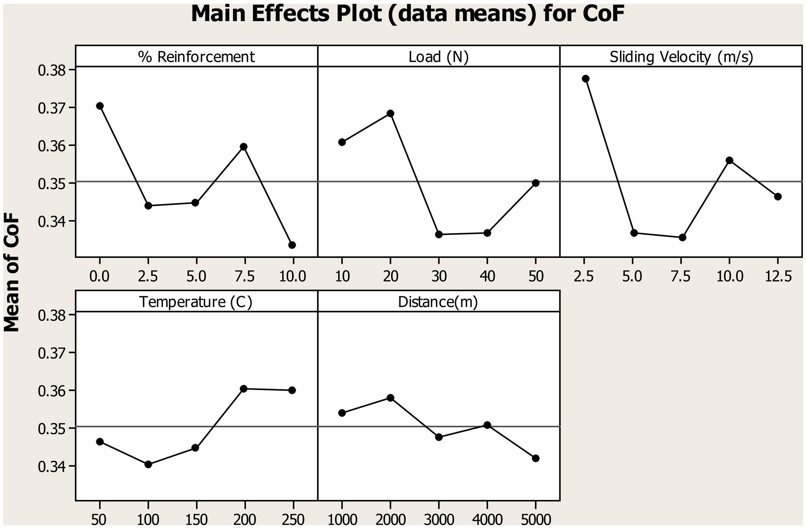
The results of the Coefficient of Friction (COF) for AA7075 hybrid composites with varying percentages of (TiO2 + Al2O3) reinforcement reveal interesting trends. As the percentage of reinforcement increases from 0% to 10%, the COF initially decreases from 0.37 to 0.32 as shown in Fig. 4. This suggests that the addition of (TiO2 + Al2O3) reinforcement has a beneficial effect on reducing the COF of the composite material. At lower COF indicates reduced friction between the sliding surfaces. This reduction in friction can lead to lower wear rates, as observed in the wear results where the wear rate decreased with increasing percentage of (TiO2 + Al2O3) reinforcement. The relationship between COF and wear rate is often inversely proportional, meaning that as the COF decreases, the wear rate tends to decrease as well. The decrease in COF with increasing reinforcement percentage can be attributed to several factors. The presence of (TiO2 + Al2O3) particles act as solid lubricants, reducing the friction between the sliding surfaces. Additionally, the reinforcement particles can enhance the load-bearing capacity of the composite, leading to smoother sliding and reduced friction. These effects contribute to the overall reduction in COF and wear rate observed in the AA7075 hybrid composites with (TiO2 + Al2O3) reinforcement.
The COF values exhibit a trend where the COF initially decreases with increasing load up to 30N and then increases at 40N and 50N. This trend can be correlated with the previously obtained wear results, where the wear rate showed a similar behavior with increasing load. The decrease in COF with up to 30N load suggests reduced friction and improved lubrication between the sliding surfaces of the composite. This phenomenon can be attributed to the load-dependent deformation of the composite material, which affect the contact area and surface interactions, leading to lower friction [21]. The decrease in COF aligns with the wear results, where the wear rate was observed to decrease with increasing load up to 30N. This indicates that the reduction in COF is associated with a decrease in wear rate, highlighting the importance of load in tribological behavior. However, at 40N and 50N, the COF increases, which could be attributed to increased contact pressure and deformation of the composite material. This increase in COF at higher loads correlates with the wear results, where the wear rate also showed an increase at 40N and 50N. This suggests that beyond a certain load threshold, the increased contact pressure and deformation lead to higher friction and wear, counteracting the benefits observed at lower loads.
The COF values exhibit a relatively stable trend with increasing sliding velocity, showing only minor fluctuations within the tested range. This behavior suggests that the sliding velocity has a limited effect on the frictional behavior of the composites within the tested range. When compared with the previously obtained wear results, where the wear rate showed a decreasing trend with increasing sliding velocity, an interesting correlation emerges. The stable COF values despite varying sliding velocities indicate that the frictional behavior of the composites is relatively consistent across different sliding speeds [22]. This suggests that factors other than sliding velocity, such as the presence of reinforcement particles and the nature of the sliding interface, have a more significant influence on the frictional behavior and wear resistance of the composites.
The COF values exhibit a slight increasing trend with increasing temperature, indicating that temperature has a minor influence on the frictional behavior of the composites within the tested range. This behavior suggests that the temperature-dependent changes in the mechanical and surface properties of the composites be contributing to the observed trend in COF. When considering the previously obtained wear results, which showed a more significant increase in wear rate with increasing temperature, the relationship between COF and wear rate becomes apparent. The slight increase in COF with temperature suggests that the frictional forces at the sliding interface increased, leading to higher wear rates at elevated temperatures. This correlation highlights the complex interplay between temperature, friction, and wear in composite materials. The COF values exhibit a slight fluctuation with increasing distance, suggesting variations in the frictional forces experienced by the composites over the sliding distance. This behavior indicates that factors such as surface roughness changes, wear debris accumulation, and lubrication effects be influencing the frictional behavior of the composites as the sliding distance increases. The observed trends in COF can be attributed to the deformation and flow of material at the sliding interface [23]. As the distance increases, the contact surfaces experience more deformation and material transfer, leading to changes in the effective contact area and surface roughness. These changes can affect the interlocking of surface asperities and the generation of frictional heat, influencing the overall frictional behavior of the composites. The reduction in COF observed at higher distances be attributed to the formation of a smoother and more wear-resistant transfer layer at the sliding interface. This transfer layer can act as a solid lubricant, reducing the direct contact between the mating surfaces and lowering the frictional forces. The presence of this transfer layer is indicative of the complex interplay between plastic flow, wear, and friction in composite materials.
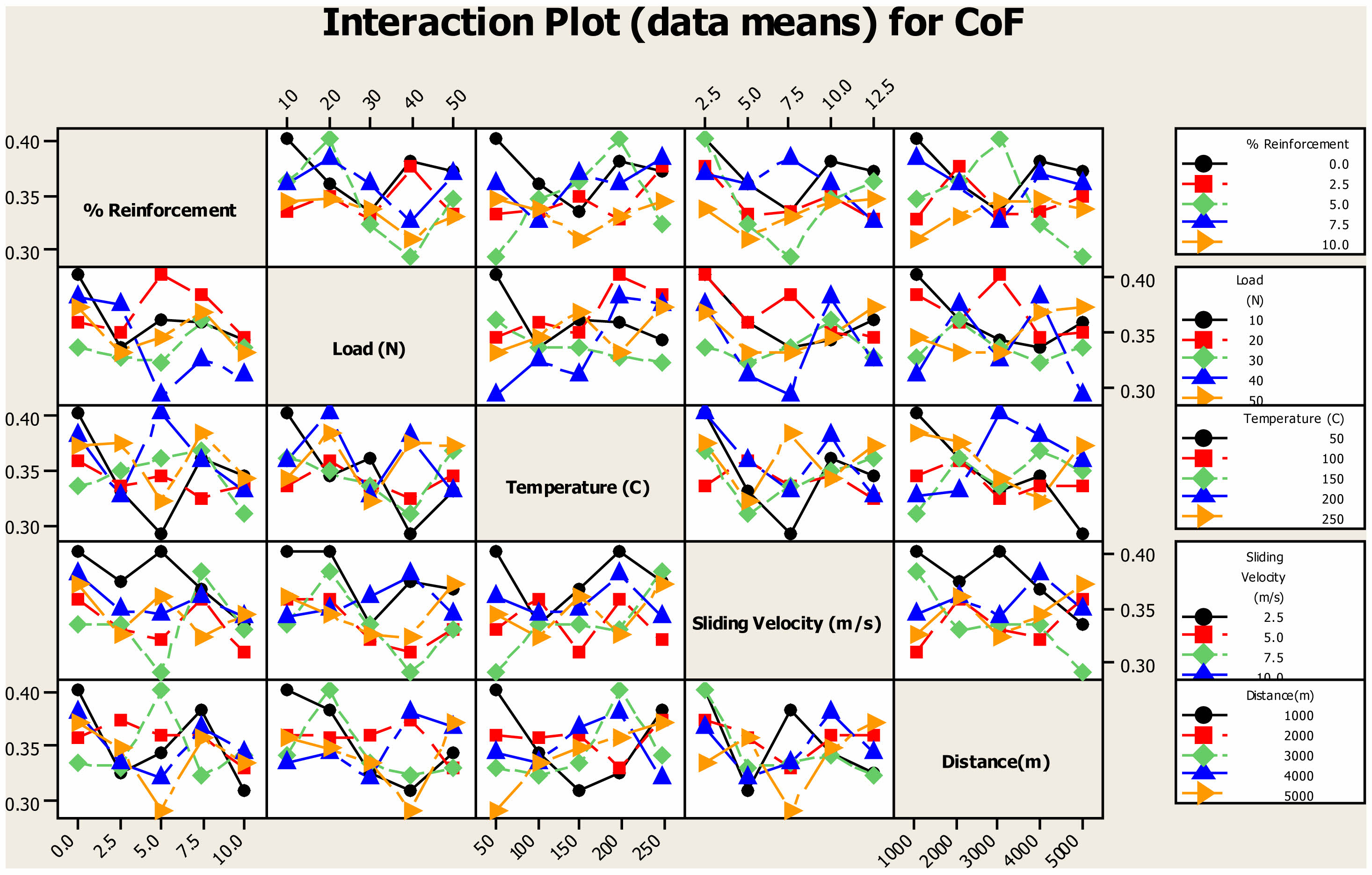
The interaction plot for distinct parameter which impact wear rate was depicted in the Fig. 5. The COF values exhibit variation with both distance and sliding velocity, indicating complex interactions between these parameters and their impact on friction. At lower sliding velocities, such as 3 m/s, the COF tends to be higher, with a value of 0.40 observed at a distance of 1000 m. This higher COF at lower velocities can be attributed to the greater interlocking of surface asperities and increased contact area between the mating surfaces, leading to higher frictional forces. As the sliding distance increases to 5000 m at the same velocity of 3 m/s, there is a slight reduction in COF to 0.35. This reduction be due to the formation of a smoother and more wear-resistant transfer layer at the sliding interface, which can act as a solid lubricant, reducing direct contact between the surfaces and lowering friction. At higher sliding velocities, such as 12 m/s, the COF is lower, with a value of 0.34 observed at a distance of 1000 m. This lower COF at higher velocities can be attributed to the reduced time for asperity interlocking and material transfer, leading to lower frictional forces. Interestingly, at the same distance of 5000 m and velocity of 12 m/s, the COF is significantly reduced to 0.3. This drastic reduction was indicative of the formation of a highly effective transfer layer or the presence of lubricating particles at the sliding interface, further reducing friction.
At lower sliding temperatures, such as 50 °C, the COF tends to be relatively low, with a value of 0.32 observed at a distance of 1000 m. This low COF at lower temperatures be attributed to reduced thermal activation of surface atoms, leading to lower adhesion and frictional forces between the sliding surfaces. As the sliding distance increases to 5000 m at the same temperature of 50 °C, there is a slight reduction in COF to 0.30. This reduction be due to the development of a more stable and protective transfer layer at the sliding interface, which can help reduce direct contact between the surfaces and lower friction. At higher sliding temperatures, such as 250 °C, the COF is higher, with a value of 0.36 observed at a distance of 1000 m. This higher COF at higher temperatures be attributed to increased thermal activation and softening of the material, leading to higher adhesion and frictional forces between the surfaces. Interestingly, at the same distance of 5000 m and temperature of 250 °C, the COF is reduced to 0.33. This reduction could be due to the formation of a more stable and lubricious transfer layer at the sliding interface, which can reduce friction and wear. The maximum COF of 0.38 was attained for a sliding temperature of 150 °C and a distance of 1000 m. This peak COF indicate a transition in the tribological behavior of the material, possibly due to changes in the transfer layer formation [24].
At a moderate sliding temperature of 50 °C, the COF is relatively low, with a value of 0.32 observed at a distance of 1000 m. This suggests that at lower temperatures, there is less energy available for surface activation and adhesion, resulting in lower friction between the surfaces. As the sliding distance increases to 5000 m at the same temperature of 50 °C, there is a slight reduction in COF to 0.30. This reduction could be attributed to the formation of a more stable and lubricious transfer layer at the sliding interface, which reduces direct contact between the surfaces and lowers friction. At higher sliding temperatures, such as 250 °C, the COF is higher, with a value of 0.36 observed at a distance of 1000 m. This increase in COF at higher temperatures is likely due to increased thermal activation of surface atoms, leading to higher adhesion and frictional forces between the sliding surfaces. However, at the same distance of 5000 m and temperature of 250 °C, the COF is reduced to 0.33. This reduction could be due to the development of a more stable and protective transfer layer at the sliding interface, which can reduce friction and wear over long sliding distances.
At a relatively low load of 10N, the COF is higher, with a value of 0.45 observed at a distance of 1000 m. This indicates that at lower loads, there is less counterforce to resist the sliding motion, leading to higher friction between the surfaces. As the sliding distance increases to 5000 m at the same load of 10N, there is a reduction in COF to 0.38. This reduction could be attributed to the development of a more stable and lubricious transfer layer at the sliding interface, which reduces direct contact between the surfaces and lowers friction. At a higher load of 50N, the COF is lower, with a value of 0.35 observed at a distance of 1000 m. This suggests that at higher loads, there is more counterforce to resist the sliding motion, leading to lower friction between the surfaces. The COF rises to 0.39 for the same 5000-meter distance and 50-node load. This increase result from higher adhesion and frictional forces caused by the increased contact pressure between the surfaces under higher weights.
At a relatively low load of 10N and a sliding velocity of 3 m/s, the COF is higher, with a value of 0.44. This indicates that at lower loads and velocities, there is less counterforce to resist the sliding motion, leading to higher friction between the surfaces. As the sliding velocity increases to 12 m/s at the same load of 10N, there is a reduction in COF to 0.38. This reduction could be attributed to the development of a more stable and lubricious transfer layer at the sliding interface, which reduces direct contact between the surfaces and lowers friction. At a higher load of 50N, the COF is lower, with a value of 0.40 observed at a sliding velocity of 3m/s. This suggests that at higher loads, there is more counterforce to resist the sliding motion, leading to lower friction between the surfaces. However, at the same sliding velocity of 12 m/s and load of 50N, the COF is reduced further to 0.34. This reduction could be due to the increased contact pressure between the surfaces at higher loads and velocities, which can lead to more efficient lubrication and lower frictional forces.
At a load of 10N and a temperature of 50 °C, the COF is measured at 0.40. As the temperature increases to 250 °C under the same load conditions, there is a slight reduction in COF to 0.39. This slight decrease in COF could be attributed to the thermal expansion of the materials, which lead to improved surface contact and reduced interfacial friction. However, at a higher load of 50N and the same temperature of 250 °C, the COF increases to 0.34. This increase in COF at higher loads and temperatures suggests that the tribological behavior of the composites is influenced by both mechanical and thermal factors. At elevated temperatures, the materials undergo changes in microstructure or surface morphology, affecting their frictional characteristics. At a distance of 1000 metres, the unreinforced alloy has a COF of 0.38, which somewhat decreases to 0.35 at 5000 metres. This decrease be the result of surface roughness variations and wear debris collection over a longer sliding distance, which improves lubrication and lowers interfacial friction. At a 10% reinforcement level, the coefficient of determination is constant at 0.38 for 1000 metres and 0.34 for 5000 metres. The constant coefficient of friction (Cof) values indicate that the reinforcement stabilises the composites’ friction behaviour, by improving the material’s resistance to wear and preserving a more stable contact interface at different sliding distances.
At a sliding velocity of 3 m/s, a COF of 0.41 is recorded for the unreinforced alloy; at 12 m/s, it drops to 0.29. The normal behaviour of materials during sliding contact, where greater velocities might lead to lower interfacial friction due to enhanced fluid film development and decreased adhesion, is consistent with this drop in COF with increasing velocity. At a 10% reinforcement level, the coefficient of determination (COT) values are 0.38 at 3 m/s and 0.36 at 12 m/s. The inclusion of reinforcement particles aid in lowering frictional forces at the interface, by increasing the load-bearing capacity and improving the lubricating characteristics of the composite, as shown by the modest drop in COF with reinforcement. For the unreinforced alloy, a COF of 0.27 is observed at a sliding temperature of 50 °C, which increases to 0.37 at 250 °C. This increase in COF with temperature can be attributed to several factors, including increased thermal expansion leading to higher contact pressures, changes in surface roughness, and alterations in the material’s mechanical properties at elevated temperatures. With a higher reinforcement level of 10%, the COF values are 0.37 at 50 °C and 0.30 at 250 °C. The variation in COF with temperature for the reinforced composite suggests that the presence of reinforcement particles can influence the tribological behavior of the material under different temperature conditions [25].
At a sliding load of 10N, a COF of 0.37 is seen for the unreinforced alloy, and at 50N, it rises to 0.39. Higher contact pressures between the sliding surfaces, which result in an increase in frictional resistance, are the cause of this rise in COF with load. At a 10% reinforcement level, the COf values are 0.41 at 10N and 0.32 at 50N. The reinforced composite’s change in COF with load indicates that the presence of reinforcement particles have an impact on the material’s tribological behaviour under various loading scenarios. This can be the result of modifications to the lubricating processes at the interface between the sliding surfaces or shifts in the composite’s deformation behaviour. The observed variations in the coefficient of friction (COF) with temperature, load, velocity, and sliding distance provide significant details on the composite material’s tribological behaviour. The intricate interactions that occur during sliding between the material’s characteristics, the environment, and the contact conditions are reflected in these variations. Comprehending these fluctuations aids in maximising operational parameters to reduce wear and friction. Thus, finer surface interactions are indicated by lower COF at shorter sliding distances, whereas stronger interfacial adhesion and plastic deformation are suggested by higher COF at higher loads. These kinds of insights are extremely helpful in the design of reliable and efficient systems, helping engineers choose the right operating conditions to maximise endurance and performance.
Worn surface morphology
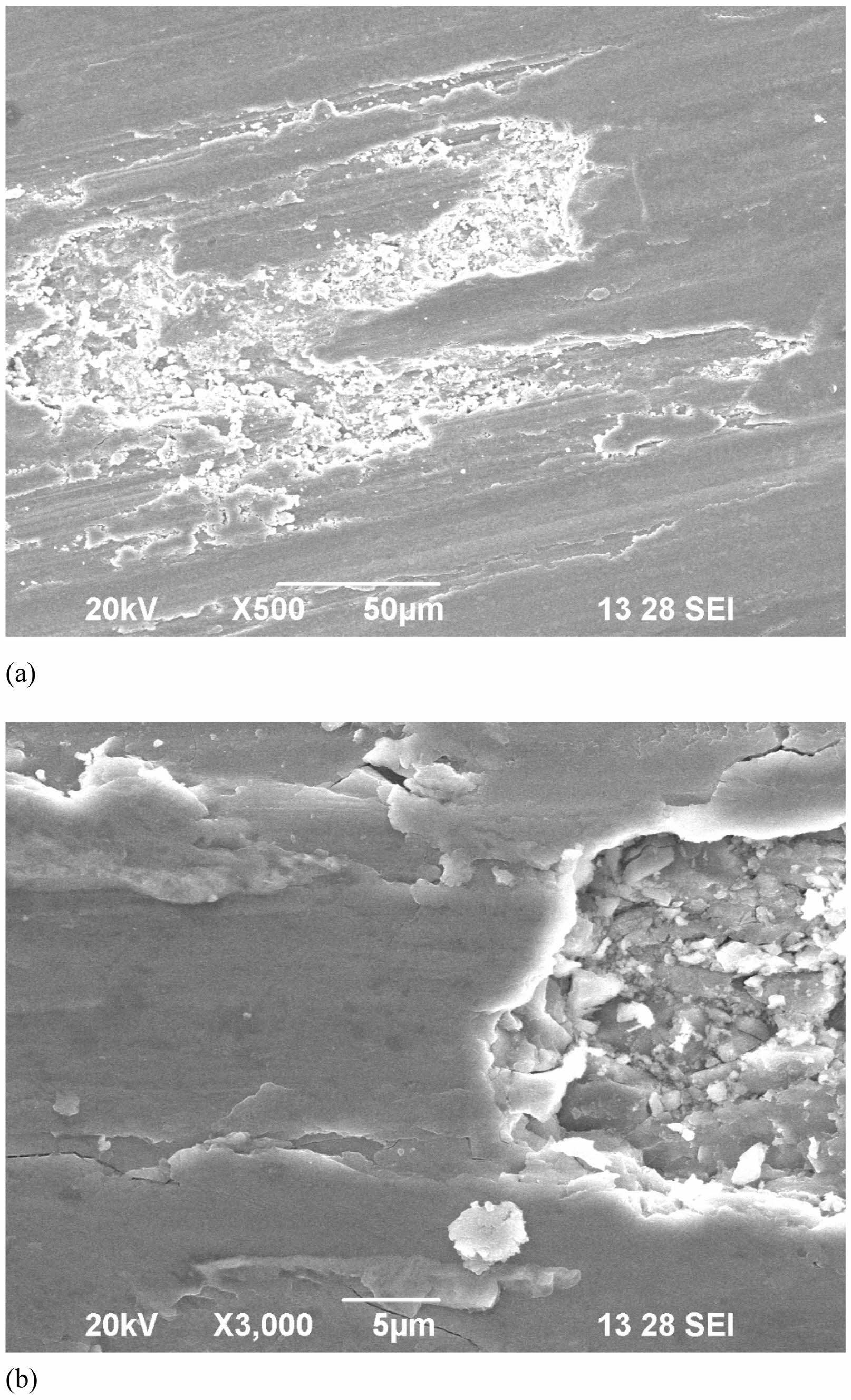
The surface of the composite pin in Fig. 6(a) exhibits rough patches and deep grooves along the sliding direction, indicative of severe abrasion. This occurs when hard asperities on the steel counterface pull out hard particles from the composite, leading to abrasion wear. The detached and fractured silicon carbide particles enter between the sliding surfaces, causing third-body abrasion and increasing the wear rate. The high hardness of the surface reduces the depth of penetration by abrasive particles, resulting in lower wear rates. The bubble-like surface indicates material resolidification, suggesting that the material reached its deformation temperature. At higher magnification, flat plate-like particles within the grooves are observed, as shown in Fig. 6(b).
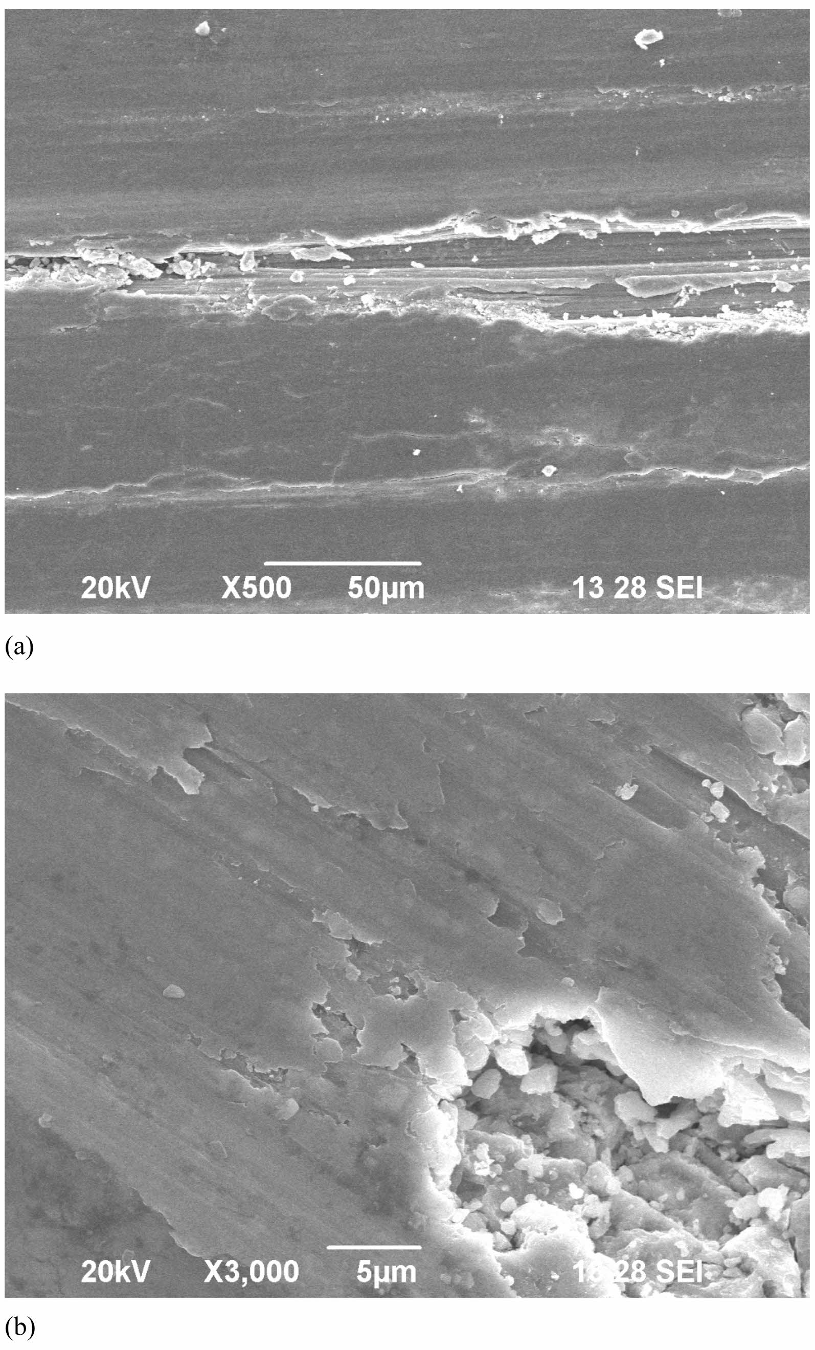
Micro-cutting occurs when particles are separated from the surface in the form of microchips, with little or no material displacement to the sides of the grooves, as seen in Fig. 7(a). The depth of micro-cutting depends on the hardness of the composites. At higher magnification, the worn surface shows brittle fracture and numerous microcracks, as shown in Fig. 7(b). These microcracks penetrate into the Mechanical Mixed Layer (MML), leading to material deformation. The presence of silicon carbide particles between the surfaces promotes cracking, indicating that the composites possess low ductility and wear resistance, leading to fragmentation. The wear rate strongly depends on three factors: i) the proportion of wear debris formed, ii) the load applied on the composites, and iii) the hardness of the composites.
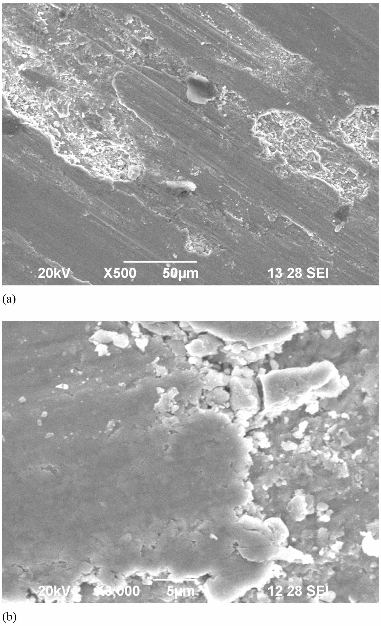
The worn surfaces in Fig. 8(a) are characterized by a large number of scratches and micro-ploughing due to the scratching and scouring action of hard particles moving over the solid surface. Wear mass loss occurs as a result of the formation of wear debris from the subsurface zones. The formation of leading and trailing edges clearly reveals plastic deformation and rising of the composites. At higher magnification, the worn surfaces show lumps due to the sheared, transferred, and redeposited wear debris, as shown in Fig. 8(b). The presence of severe abrasion with rough patches, deep grooves, and third-body abrasion with detached particles indicates significant material loss and deformation, which can negatively impact the overall wear resistance and longevity of AA7075 hybrid composites in real-world applications. These wear mechanisms can lead to increased friction, wear rates, and material degradation, potentially reducing the performance and lifespan of components made from these composites.
|
Fig. 1 SEM of AA7050 hybrid composites. |
|
Fig. 2 Main effect plot of AA7075 hybrid composites. |
|
Fig. 3 Interaction plot for wear of AA7075 Hybrid composites. |
|
Fig. 4 Main effect plot of COF of AA7075 hybrid composites. |
|
Fig. 5 Interaction plot for COF of AA7075 Hybrid composites. |
|
Fig. 6 Worn surface morphology of AA7075 hybrid composites (2.5 -Al2O3+2.5-TiO2) (a) At 500x (b) At 3000x. |
|
Fig. 7 Worn surface morphology of AA7075 hybrid composites (5 -Al2O3+5-TiO2) (a) At 500x (b) At 3000x. |
|
Fig. 8 Worn surface morphology of AA7075 hybrid composites (7.5 -Al2O3+7.5-TiO2) (a) At 500x (b) At 3000x. |
The wear rate of AA7075 hybrid composites exhibits a non-linear trend with increasing reinforcement percentage, showing the lowest wear rate at 7.5% reinforcement. At higher reinforcement percentages (10%), a slight increase in wear rate is observed, indicating a possible saturation effect or change in wear mechanism. The presence of reinforcing particles reduces wear rate by acting as obstacles to prevent direct contact between mating surfaces, thus reducing abrasion. The wear behavior shows the formation of a mechanical mixed layer (MML) during sliding, which contributes to reducing wear rate. Increasing load from 10N to 30N leads to a significant decrease in wear rate, suggesting improved wear resistance due to increased contact pressure and MML formation.
A slight increase in wear rate was observed at 40N and 50N, possibly due to more severe abrasive wear or deformation mechanisms. Increasing sliding velocity from 2.5 m/s to 12.5 m/s leads to a decrease in wear rate, indicating improved wear resistance with higher sliding speeds. Wear rate decreases with increasing sliding distance, indicating improved wear resistance over longer sliding distances, but a slight increase is observed at 5000m, possibly due to wear debris accumulation. The wear behavior exhibits distinct regions based on sliding distance and velocity, with optimal wear resistance observed at moderate sliding distances (2250-3500 m) and velocities (8-12 m/s).
The coefficient of friction (COF) initially decreases with increasing reinforcement percentage, indicating reduced friction between sliding surfaces. COF decreases with increasing load up to 30N, suggesting reduced friction and improved lubrication, but increases at higher loads, possibly due to increased contact pressure and deformation. Sliding velocity has a limited effect on COF, indicating relatively consistent frictional behavior across different speeds. COF exhibits a slight increase with increasing temperature, suggesting minor influence of temperature on frictional behavior within the tested range.
COF shows variation with sliding distance, indicating changes in frictional forces over the sliding distance, possibly due to surface roughness changes and wear debris accumulation. COF exhibits complex interactions between sliding distance and velocity, indicating variations in frictional behavior with different combinations of these parameters. COF tends to be higher at lower loads, lower sliding velocities, and lower temperatures, indicating higher frictional forces under these conditions. The inclusion of reinforcement particles stabilizes the COF values, suggesting improved resistance to wear and a more stable contact interface.
The worn surface of the composite pin showed severe abrasion with rough patches and deep grooves. Abrasion wear is caused by hard asperities pulling out hard particles. Third-body abrasion occurs with detached silicon carbide particles. Micro-cutting results in microchips, and worn surfaces exhibit scratches, micro-ploughing, and lumps from wear debris.
- 1. D.K. Rajak, D.D. Pagar, R. Kumar, and C.I. Pruncu. J. Mater. Res. Technol. 8[6] (2019) 6354-6374.
-

- 2. A. K. Sharma, R. Bhandari, A. Aherwar, R. Rimašauskienė, and C. Pinca-Bretotean, Mater. Today: Proc. 26 (2020) 2419-2424.
-

- 3. D.K. Rajak, P.H. Wagh, P.L. Menezes, A. Chaudhary, and R. Kumar, J. Bio-Tribo-Corros. 6[1] (2020) 1-18.
-

- 4. R. Casati and M. Vedani, Metals 4[1] (2014) 65-83.
-

- 5. R. Ranjith and P.K. Giridharan, High Temp. Mater. Processes. 19[3-4] (2015).
-

- 6. E. Candan, H. Ahlatci, and H. Çı̈menoğlu, Wear 247[2] (2001) 133-138.
-

- 7. J. Hashim, L. Looney, and M.S.J. Hashmi, J. Mater. Process. Technol. 92 (1999) 1-7.
-

- 8. K.F. Ehmann, S.G. Kapoor, R.E. DeVor, and I. Lazoglu, J. Manuf, Sci. Eng. Trans. ASME. 119[4B] (1997) 655-663.
-

- 9. T.D. Ngo, A. Kashani, G. Imbalzano, K.T. Nguyen, and D. Hui, Composites, Part B 143 (2018)172-196.
-

- 10. J.R. Gamage and A.K.M. DeSilva, Procedia CIRP 26 (2015) 385-390.
-

- 11. R. Ranjith and P.K. Giridharan, J. Mater. Environ. Sci., 8(2017) 1168-1172.
- 12. S. Pattnaik and M. K. Sutar. Silicon (2021) 1-12.
-

- 13. C. Senthilkumar, G. Ganesan, and R. Karthikeyan, Int. J. Appl. Sci. Eng. 11[1] (2013) 13-24.
- 14. M. Gostimirović, D. Rodić, M. Sekulić, and A. Aleksić, Adv. Technol. Mater. 45[1] (2020) 1-8.
-

- 15. R. Ranjith, P.K. Giridharan, and M. Subramanian, Int. J. Comput. Mater. Sci. Surf. Eng., 8[2] (2019) 89-99.
-

- 16. P. Sudha, S. Ramesh, R. Jagadeesan, and K. Yuvaraj, J. Ceram. Process. Res., 25[1] (2024)1-15.
-

- 17. H.K. Kansal, S. Singh, and P. Kumar. J. Mater. Process. Technol. 184[1-3] (2007) 32-41.
-

- 18. B. Ekmekci, Appl. Surf. Sci. 253[23] (2007) 9234-9240.
-

- 19. M. Verapathran, S. Vivek, G.E. Arunkumar, and D. Dhavashankaran, J. Ceram. Process. Res. 24[1] (2023) 89-97.
-

- 20. P.E. Gill, W. Murray, and M.H. Wright, Soc. Ind. Appl. Math., (2019).
- 21. M.C. Fu. Informs J. Comput. 14[3] (2002) 192-215.
-

- 22. T. Sivaa and K. Anandavelu, J. Ceram. Process. Res., 24[2] (2023) 406-414.
-

- 23. S. Sardar, S.K. Karmakar, and D. Das, J. Tribol. 141[4] (2019).
-

- 24. R. Ranjith, S.N.V. Kumar, P.K. Giridharan, and V.P. Pradeep, High Temp. Mater. Process, 25[4] (2021).
-

- 25. R. Ranjith, S. Venkatesan, N.S. Sivakumar, and P.N. Kumar, Mater. Sci. Eng. 1070[1] (2021, February) 012135. IOP Publishing.
-

 This Article
-
2024; 25(6): 1142-1153
Published on Dec 31, 2024
- 10.36410/jcpr.2024.25.6.1142
- Received on Apr 5, 2024
- Revised on May 16, 2024
- Accepted on Jul 5, 2024
 Services
Shared
 Correspondence to
- N.H. Agilandeswari
-
Assistant Professor, Department of Civil Engineering, E.G.S. Pillay Engineering College, Nagappattinam 611002, Tamilnadu, India
Tel : +9884418131 - E-mail: agilace8083@gmail.com


 Copyright 2019 International Orgranization for Ceramic Processing. All rights reserved.