- Machining of Ti6Al4V under Cu particle mixed dielectric medium using aluminium composite tool for production of electric motors components
G. Radhakrishnana,*, J. Jebeen Mosesb, M. Felix Xavier Muthuc and Sudharsan Gunasekarand
aAssociate Professor, Department of Electrical and Electronics Engineering, Sri Krishna College of Engineering and Technology, Coimbatore- 641 008
bAssistant Professor, Department of Mechanical Engineering St. Xavier’s Catholic College of Engineering Chunkankadai, Nagercoil, Tamil Nadu, India
cAssociate Professor, Department of Mechanical Engineering St. Xavier’s Catholic College of Engineering Chunkankadai, Nagercoil, Tamil Nadu, India
dAssistant Professor, Department of Mechatronics Engineering, Sona College of TechnologyThis article is an open access article distributed under the terms of the Creative Commons Attribution Non-Commercial License (http://creativecommons.org/licenses/by-nc/4.0) which permits unrestricted non-commercial use, distribution, and reproduction in any medium, provided the original work is properly cited.
The research investigates the impact of process parameters on the Material Removal Rate (MRR), Tool Wear Rate (TWR), and surface roughness (Ra) of a Titanium alloy under Copper (Cu) mixed Electric Discharge Machining (PMEDM) using an Aluminium – 10%graphite (A2) composite tool material. Under optimal conditions of Pon=60 µs, Poff=8 µs, and current=7A, machining with an A2 composite tool achieved an MRR of 0.1 mm³/min, a TWR of 0.0016 mm³/min, and an Ra of 0.847 µm. The introduction of 5 g/l of Cu powder into the dielectric fluid minimized TWR to 0.00122 mm³/min, indicating that the powder effectively absorbed and dissipated heat, reducing tool wear. At 10 g/l, TWR peaked due to the bridging effect, where particles created a barrier between the tool and workpiece, increasing tool wear. Beyond 10 g/l, TWR decreased due to debris densification, where the particles compacted together, reducing their ability to absorb heat and protect the tool. Surface roughness with a minimum Ra of 2.69 µm achieved at 5 g/l, but worsening as the concentration increased, reaching a mean Ra of 6.29 µm at 25 g/l. Ra also increased with higher Pon values, peaking at 5.81 µm at 75 µs Pon, indicating that longer pulse-on times allowed more heat to accumulate, leading to greater surface irregularities. Higher currents led to increased Ra, indicating surface quality reduction due to the intense heat generated, which could cause melting and re-deposition of material on the surface. SEM analysis revealed distinct surface characteristics based on the concentration of Cu powder in the dielectric fluid. At higher concentrations (25 g/l), the surface exhibited deep pits, craters, and globules, indicating excessive heat generation and inadequate flushing of machined debris. Lower concentrations (10 g/l) showed reduced pit and crack sizes, with some carbon content deposition from the dielectric fluid. Further reduction to 5 g/l significantly improved surface quality, with minimal cracks and redeposited material.
Keywords: EDM , Optimization , Surface topography , Machining , Dielectric
Composite materials are widely employed in many sectors due to their better mechanical, thermal, and electrical qualities as compared to traditional materials [1]. Composite materials are made by mixing two or more separate components to form a new material with improved qualities [2]. Composites can be made using a variety of techniques, each with unique benefits and drawbacks. Powder metallurgy compacts metal powders and reinforcing particles into a mould attains uniform distribution but less suitable for large-scale production [3]. In-situ fabrication involves the formation of reinforcing particles within the matrix, requires specialized equipment and expertise. Squeeze casting is a method for manufacturing composites that involves pouring molten metal into a preheated die cavity and applying pressure to force the metal into the mold cavity and limited in terms of the size and complexity of the parts that can be produced [4]. Stir casting is a widely used method for manufacturing composites that involves melting a metal matrix and adding reinforcing particles to create a homogeneous mixture, which is then solidified to form the composite material. Stir casting is relatively simple, cost-effective, and suitable for large-scale production, hence it was preferred over other manufacturing methods [5]. Composite tools can be employed to improve the machining accuracy and reduce tool wear in unconventional machining process.
The production of stator and rotor components for electric motors is a vital procedure in the electrical engineering sector, requiring high accuracy and complicated machining abilities [6]. Traditional machining processes frequently fail to fulfil the demanding requirements of these components, resulting in issues such as tool wear, poor surface smoothness, and dimensional inaccuracy [7]. To address these issues, a variety of unconventional machining technologies have been developed, each with its own set of benefits and limits. Laser Beam Machining (LBM) provides excellent accuracy, but is limited by the material’s reflectance and thickness [8]. Plasma Arc Machining (PAM) achieves high MRR but difficulties with complex geometries and tight tolerances, Abrasive Jet Machining (AJM) is suitable for machining heat-sensitive materials but has lower MRR, Water Jet Machining (WJM) is effective for cutting a wide range of materials but its precision level is comparatively low, Hence EDM has emerged as a leading choice for the high-precision manufacturing of stator and rotor components [9-12].
The performance of the EDM process is influenced by several key parameters, including the choice of tool and workpiece material, spark gap, discharge current, voltage, and pulse duration [13]. Spark gap prevents arcing, which can cause surface damage and tool wear, and regulates the effective removal of machined debris [14]. The discharge current determines the intensity of the sparks and the rate of material removal, with higher currents typically leading to faster material removal but also increased tool wear [15]. Pulse duration affects the size and shape of the sparks, with shorter pulses typically producing finer surface finishes but also requiring longer machining times [16]. To endure the high temperatures produced during the machining process, the tool material needs to be both electrically conductive and have a high melting point. Copper, graphite, and brass are common materials for tools, while materials for workpieces includes from steel, aluminium, titanium and superalloys [17]. Copper tools excel in high MRR suitable for rough machining whereas graphite tools are ideal for finishing with excellent machinability. Brass tools achieve high MRR and Ra for high melting point materials but Aluminum tools offer high MRR but lacks wear resistance and compatibility with certain workpiece materials [18]. Copper-tungsten tools provide high MRR and excellent TWR, albeit at a higher cost and requiring special handling to prevent damage.
Powder Mixed Electric Discharge Machining (PMEDM) enhances machining by introducing powder particles like aluminum oxide (Al2O3), silicon carbide (SiC), boron carbide (B4C), and aluminum into the dielectric fluid [19]. These powders improve spark erosion and reduce tool wear, impacting PMEDM performance through effects like the bridging effect, stabilizing spark gap, and increments gap distance [20]. The bridging effect involves powder particles forming bridges between tool and workpiece, stabilizing the spark gap for higher MRR and improved Ra [21]. The incremental spark gap reduces the effective spark gap, boosting spark density for efficient material removal and lower TWR. Al2O3 in PMEDM enhances MRR and Ra due to its thermal conductivity and low density [22]. SiC and B4C improve MRR and surface finish by reducing tool wear and enhancing spark gap stability [23]. Despite the extensive research on composite materials, there is a significant gap in the specific application of composite as a tool material in EDM processes [24]. While several research have explored the use of composite materials in EDM, the effectiveness of Aluminium-10%graphite (A1) composite, especially when combined with the addition of copper in the dielectric fluid, remains relatively unexplored [25]. Hence in this work, an attempt was made to use A1 as tool material using stir casting with the objective of combining the properties of two tool materials and incorprating conductive copper powder in the dielectric medium to enhance the EDM machining performance.
Materials
Ti-6Al-4V, a medical grade titanium alloy has found its application in biomedical and aerospace space was selected for investigation. Its chemical composition was shown in the Table 1. The matrix material selected for the tool material were AA6061 aluminium alloy and its chemical composition was depicted in the Table 2. The AA6061 was procured from the sector, perfect metal alloys, bangalore. Particulate reinforcement composites have found its application in aerospace and defence sector. In this research work graphite was used as the reinforcing element and it was selected with an objective of integrating properties of both the metals. The Gr particles were purchased from the firm bhukhanwala industries, mumbai. The fine magnesium powder of particle size 1 µm was added as the flux which was purchased from coimbatore metal mart, coimbatore. Cu apowder were used as the EDM dielectric additives, procurred from the alpha chemika, mumbai.
Manufacturing of composites
About 1 kg of AA6061 aluminium alloy was placed in the graphite crucible and heated to the temperature of 750 ᵒC. The Gr particulates of average particle size 5 µm was preheated to the temperature of 400 ᵒC for the time span of 90 mins to remove the moisture content in it. The preheated particles disburses more uniformly than the untreated composites. The permanent mould made of die steel was preheated to the temperature of 250 ᵒC to eliminate the surface defect, when the molten metal was being poured into it [26]. In order to incorporate the Gr particles in the AA6061 alloy, it was required to heat the metal to the temperature of 900 ᵒC. At such high temperature the composite developed the intermetallic compounds which deteriorates the material property, more probably it will turn brittle. In order to avoid it, Mg powder was added as the flux material [27]. The added magnesium powder coats the reinforced particles, thereby facilitates the bonding of matrix and particles. Once after the AA6061 alloy completely melted, the preheated Gr particles were added to the melt. The mixture was stirred using the three-arm mechanical stirrer at the speed of 1000 rpm for 3 mins. Followed by the Mg powder was added to the charge, the weight of the flux added was equal to the weight of the reinforcing particles. The mixture was stirred again at the 1000 rpm for 2 mins. The mixture was poured into the preheated mould made of die steel. The composites of dimensions 105 mm × 105 mm × 7 mm (L × B × T) was produced and machined to the dimension of 100 mm × 100 mm × 6 mm to remove the surface defects.
EDM
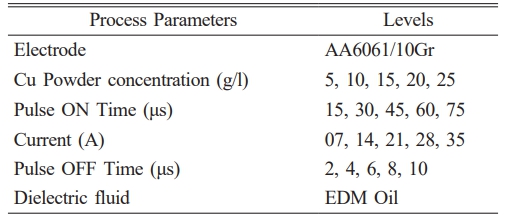
EDM Experiments were performed by varying current, powder concentration, Pon and Poff. Its process parameters were shown in the Table 3. The experimental runs were designed using Taguchi L25 orthogonal array. The Ti-6Al-4V were connected to cathode and tool were connected to the anode. A dial gauge was used to position the tool vertically in the electric discharge machine. The machined performance was analysed in terms of MRR, TWR and Ra. Each experiment was machined for the 10 mins and repeated for three times. Addition of foreign particles in the dielectric fluid improves the machining performance. In order to enhance the machining performance Al2O3 and Cu powder was incorporated in the dielectric fluid. A special setup was developed to perform the machining in the Powder Mixed Electric Discharge Medium (PMEDM). It comprises of a motor in which mechanical stirrer was connected to it, it was rotated at stipulated speed with an objective of suspending incorporated particles in the dielectric fluid. A pump was utilized for pumping of dielectric fluid, it performs the function of flushing and cooling of workpiece [28].
The weight of the work piece was measured before and after machining using the weigh balance machine of high accuracy. MRR is the ratio of weight difference to the product of density and machined time as depicted in the Eq. (1). The unit of MRR was expressed in terms of mm3/min.

Yb, Ya – Weight of the specimen before and after machining.
t – Machined time in minutes.
Δ – Density of the titanium alloy
Tool Wear Rate (TWR)
The weight of the tool was measured afore and after the machining using the weighing machine. TWR is the ratio of weight difference of tool materials to the product of machined time and density of the electrode as depicted in the Eq. (2). The TWR was expressed in terms of mm3/min.

Yb, Ya – Weight of the specimen before and after machining.
t – Machined time in minutes.
Δ – Density of the Tool material
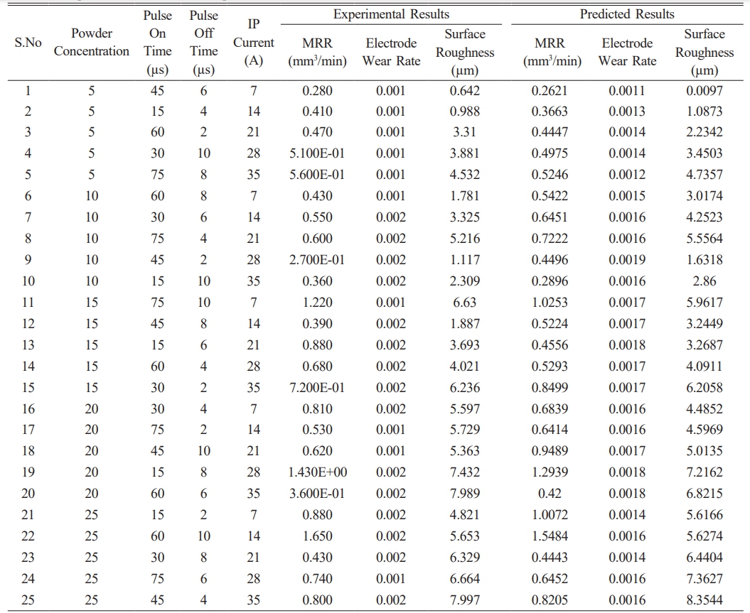
The Surf tester has an accuracy and resolution range of 0.01 µm to 0.4 µm. The roughness value was measured at ten different location and the average value was recorded as the Ra value. The experimental results were shown in Table 4.
Material Removal Rate
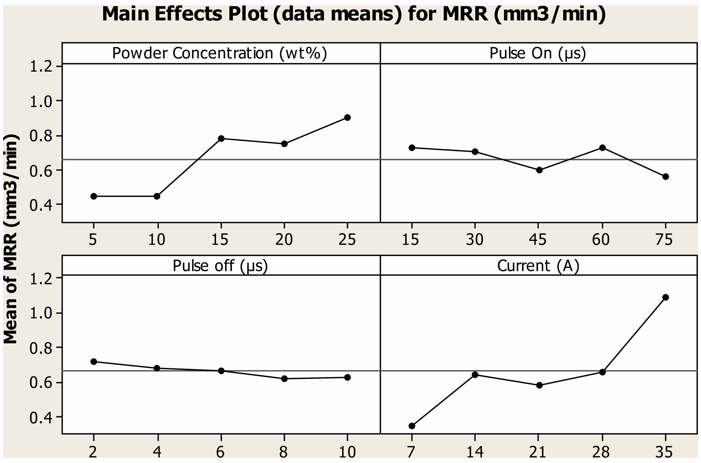
The impact of various process parameter on MRR of Ti alloy under Cu mixed dielectric medium was depicted in the Fig. 1. When machined under unmixed dielectric medium the optimal parameter setting were 60 µs, 8 µs and 7A machined with A2 composite tool. The MRR, TWR and Ra attained for above parametric setting were 0.1 mm3/min, 0.0016 mm3/min, 0.847 µm respectively. When 5 g/l of Cu powder was incorporated in the dielectric fluid MRR was increased to 0.280 mm3/min and it was increased to 1.650 mm3/min when the concentration was increased to 25 g/l. For the same machining condition when 10 g/l of Al2O3 particles were added, MRR of 3.2 mm3/min was obtained which was 93% higher that Cu PMEDM. The reduction in MRR was attributed to fact owing to the high thermal conductivity of Cu powder the generated heat was observed by the powder and gets melted and evaporated (Hosni et al., 2018). Owing to which amount of heat struck the machined surface was lowered, hence MRR reduces [29].
The factor Pon has very minimal impact on the MRR, with raise in Pon, MRR reduces from 0.74 mm3/min to 0.56 mm3/min. The result revealed that when powder particles were incorporated, maximum MRR was attained at lower Pon parametric value regardless of the characteristics of powders [30]. At higher Pon, the generated heat was hanged on for extended period of time, hence more volume of materials was removed from the surface. With raise in Poff time, MRR slightly reduces from 0.72 mm3/min to 0.62 mm3/min. Poff time essential for flushing of debris and cooling of workpiece [31]. At this span of time no machining occurs, hence with increase in Poff MRR decreases. Current was the most significant factor which influences the MRR of Ti alloy under Cu mixed PMEDM. When there was rise in current from 28A to 35A, the transition of mild to severe MRR was observed. At higher current, it generates the discharge of high intensity which removes the higher volume of materials.
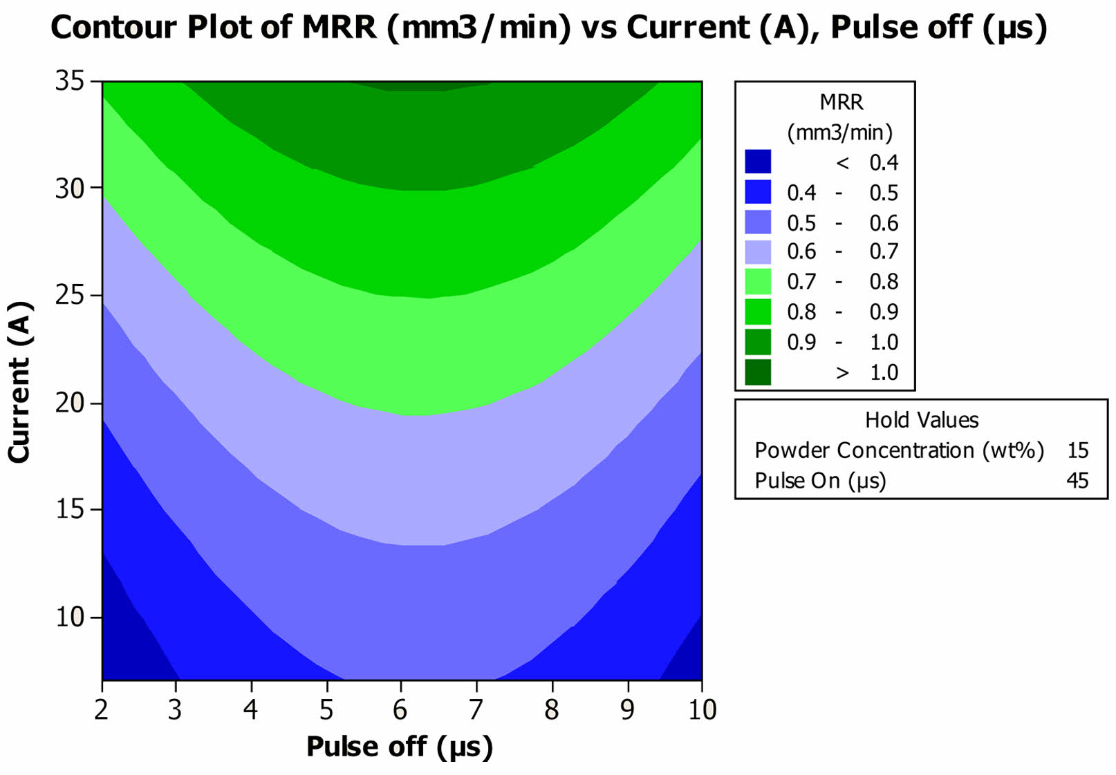
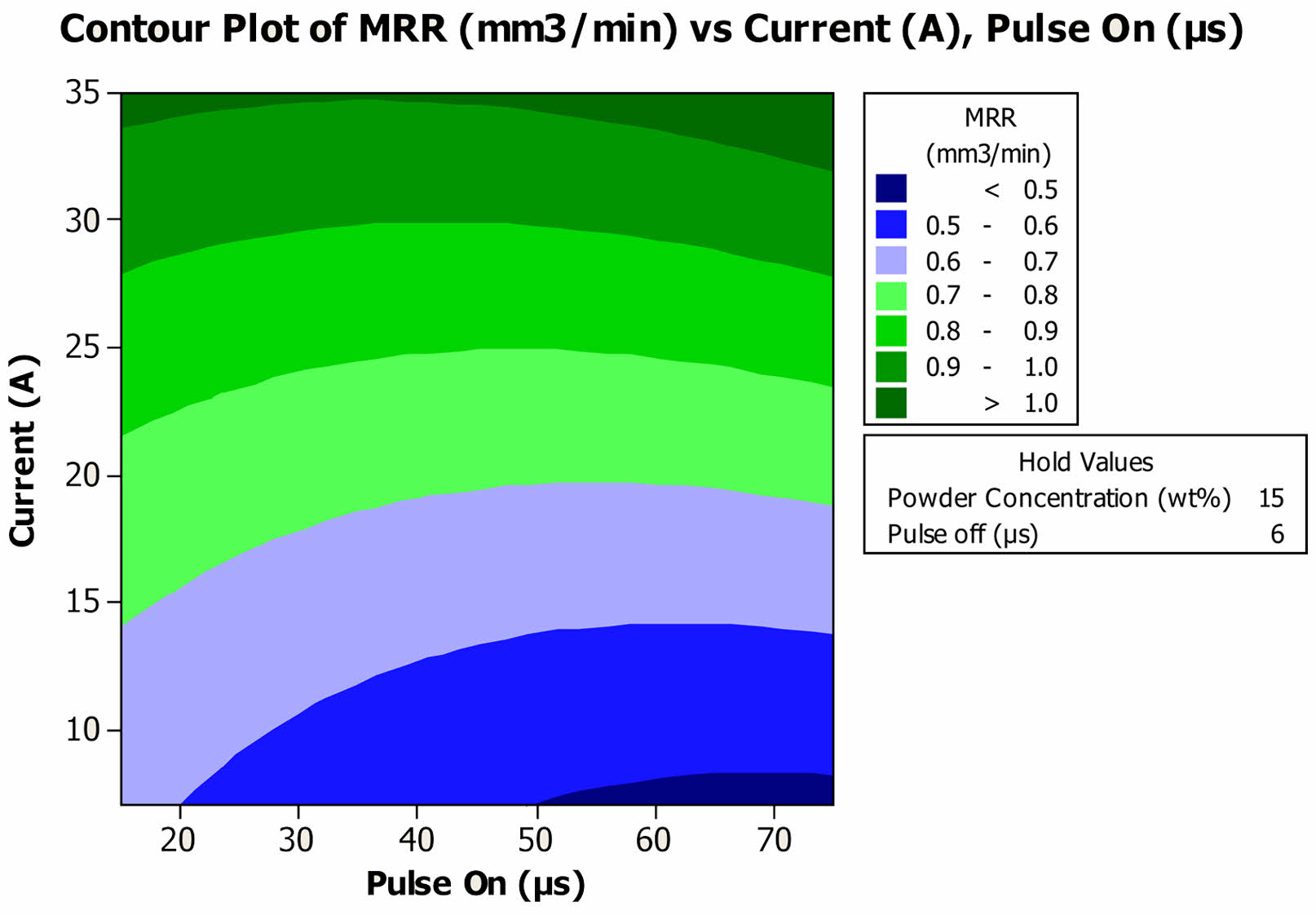
When the current and Poff was tuned at lower parametric level of 7A and 2 µs, MRR of 0.31 mm3/min was attained and it was increased to 1 mm3/min for the current and Poff of 35A and 6 µs respectively as shown in the Fig. 2. When the current was fixed at any set of parametric levels, MRR increases until a saddle point of 6 µs thereafter it declines. MRR increases with raises in current, regardless of the value of Poff. Least MRR of 0.48 mm3/min was observed when the value of current and Pon was tuned at 7A and 75 µs respectively and it was drastically increased to 1.07 mm3/min when the current value was increased to 35A as shown in Fig. 3. When the Pon was fixed at lower level of 10 µs, MRR was increased from 0.62 mm3/min to 1.02 mm3/min when there is swift in values from 7A to 35A respectively.
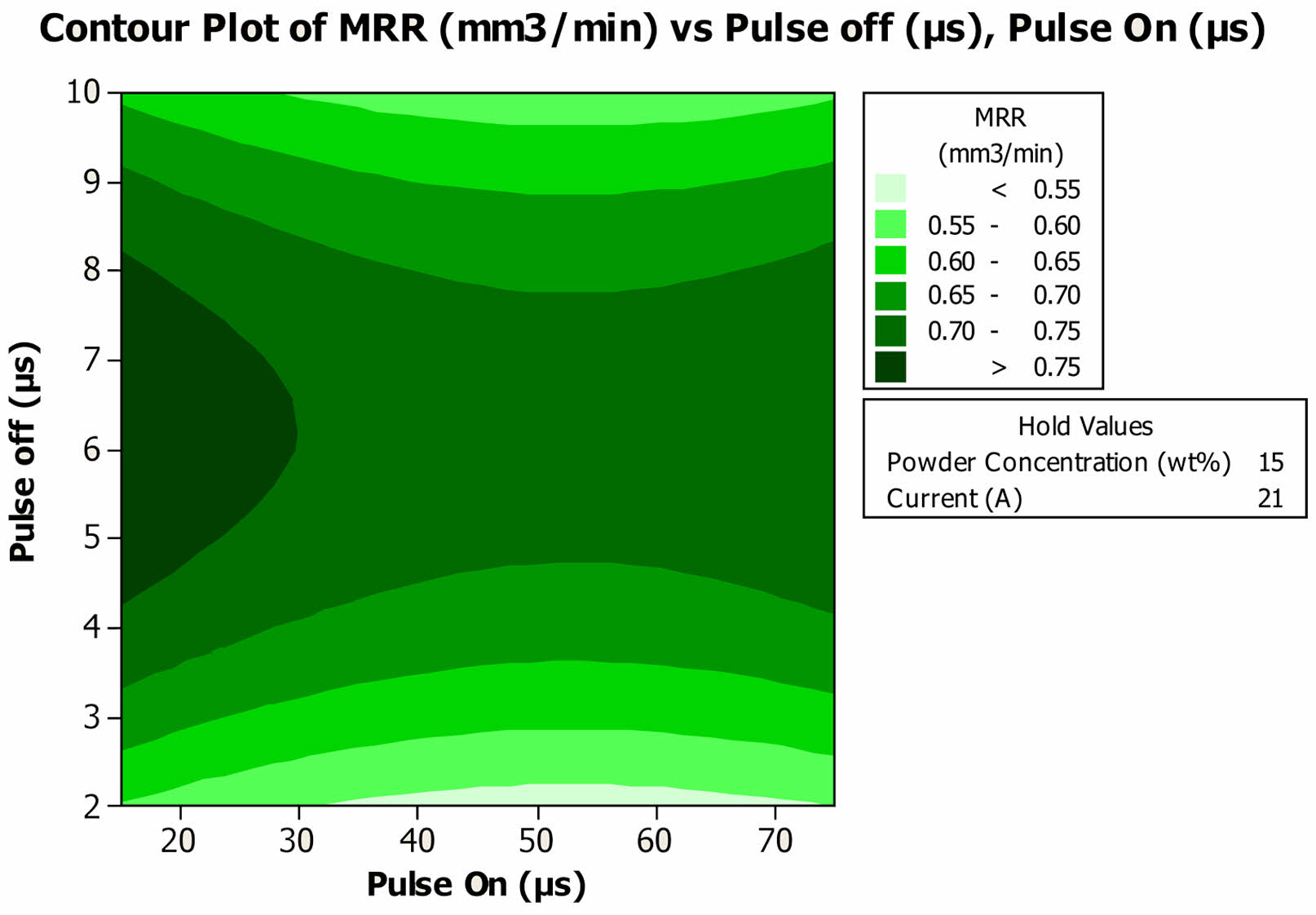
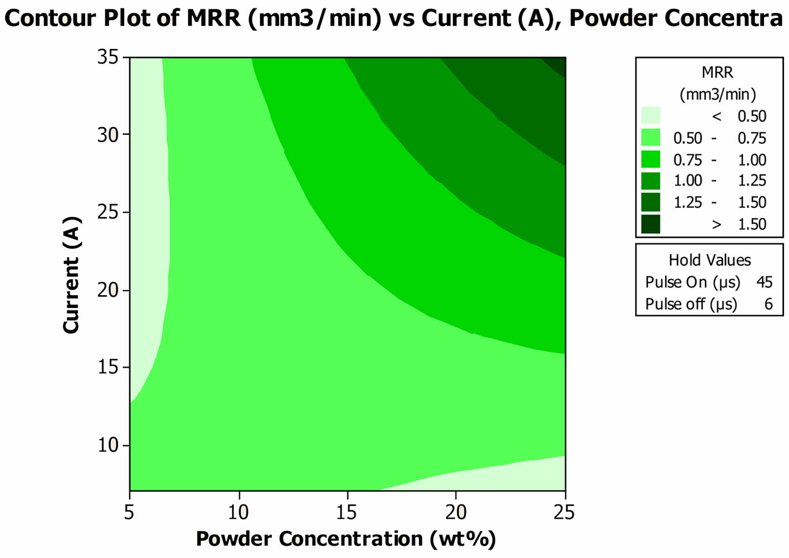
The cycle time was termed as the ratio of Pon to the sum of the Pon and Poff. For the cycle time of 0.625, MRR of 0.79 mm3/min was attained as shown the Fig. 4. Either increase or decrease in cyle time reduces the MRR. At higher parametric value of 75 µs and 10 µs MRR slightly reduced to 0.59 mm3/min. and it was further reduced to 0.52 mm3/min for 2 µs, Poff. The interaction impact of current and powder concentration was depicted in the Fig. 5. When 5 g/l of powder particles were incorporated in the dielectric fluid, MRR reduces from 0.54 mm3/min to 0.40 mm3/min with raise in current from 7A to 35A. At lower powder concentration, the generated heat was absorbed by the incorporated powder particles, hence MRR reduces. Interestingly, at higher powder concentration of 25 g/l, MRR increases with raise in current and reaches a maximum of 1.55 mm3/min for 35A current. At higher concentration, particles causes the bridging effect, Hence MRR increases [32].
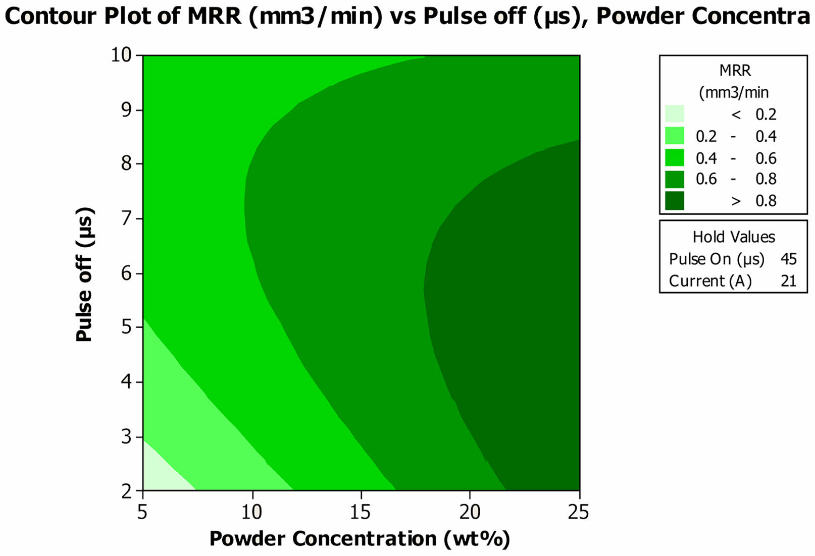
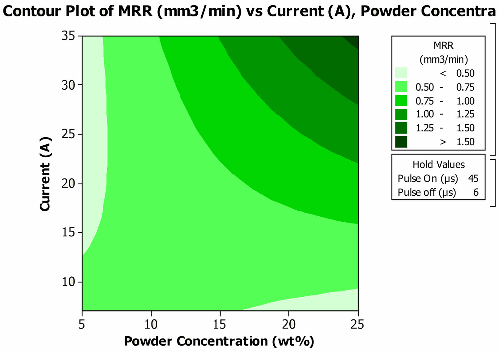
At the powder concentration of 25 g/l, MRR ranges around 0.95 mm3/min was observed for the Poff ranges between 2 µs to 8µs and it reduces to 0.65 mm3/min for 10 µs Poff as shown in Fig. 6. In case of 5 g/l contaminated dielectric medium, MRR gradually increases from 0.09 mm3/min to 0.47 mm3/min. In main effect plot MRR were reduced with increase in Poff whereas in this interaction plot it increases at particular concentration. The results revealed that interaction of Poff and powder concentration has significant effect on the MRR. Incorrect combination of parameters results in lowering of MRR. A linear graph was observed with regards to the interaction impact of Pon and powder concentration as shown in Fig. 7. MRR decreases with increase in Pon at fixed level of powder concentration. A maximum MRR of 1.03 mm3/min was obtained for the powder concentration of 25 g/l at 10 µs Pon. Dielectric conditions improve machining precision and surface quality, crucial for high-performance motor parts where tolerance and reliability are significant. By reducing defects like cracks and enhancing surface integrity, manufacturers can achieve higher efficiency and cost-effectiveness.
MRR = 0.0594550 + 0.0159010 Powder Concentration (wt%) - 0.00556811 Pulse On (µs) + 0.199742 Pulse off (µs) - 0.0289559 Current (A) - 2.65745E-04 Powder Concentration (wt%) * Powder Concentration (wt%) + 4.71080E-05 Pulse On (µs)*Pulse On (µs) - 0.0109681 Pulse off (µs)*Pulse off (µs) + 0.000165292 Current (A)*Current (A) - 1.26466E-04 Powder Concentration (wt%)* Pulse On (µs) - 0.00418750 Powder Concentration (wt%)*Pulse off (µs) + 0.00230671 Powder Concentration (wt%)*Current (A) + 0.000117494 Pulse On (µs)*Current (A) (1)
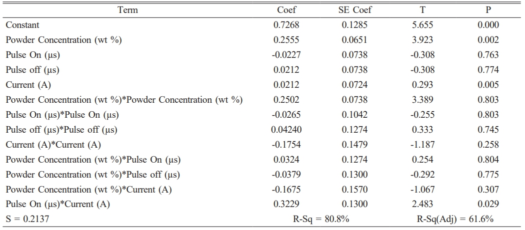
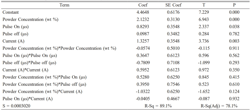
Table 5 displays the predicted regression coefficient. The parameters with a P value less than 0.05 were the most relevant factor since the experimental runs were designed with a 95% confidence level. Eq. (1) depicts the mathematical model for forecasting MRR. As shown in Table 6, the most significant factors that have an influence on MRR are powder concentration, current and interaction of powder concentration and current.
Tool wear Rate
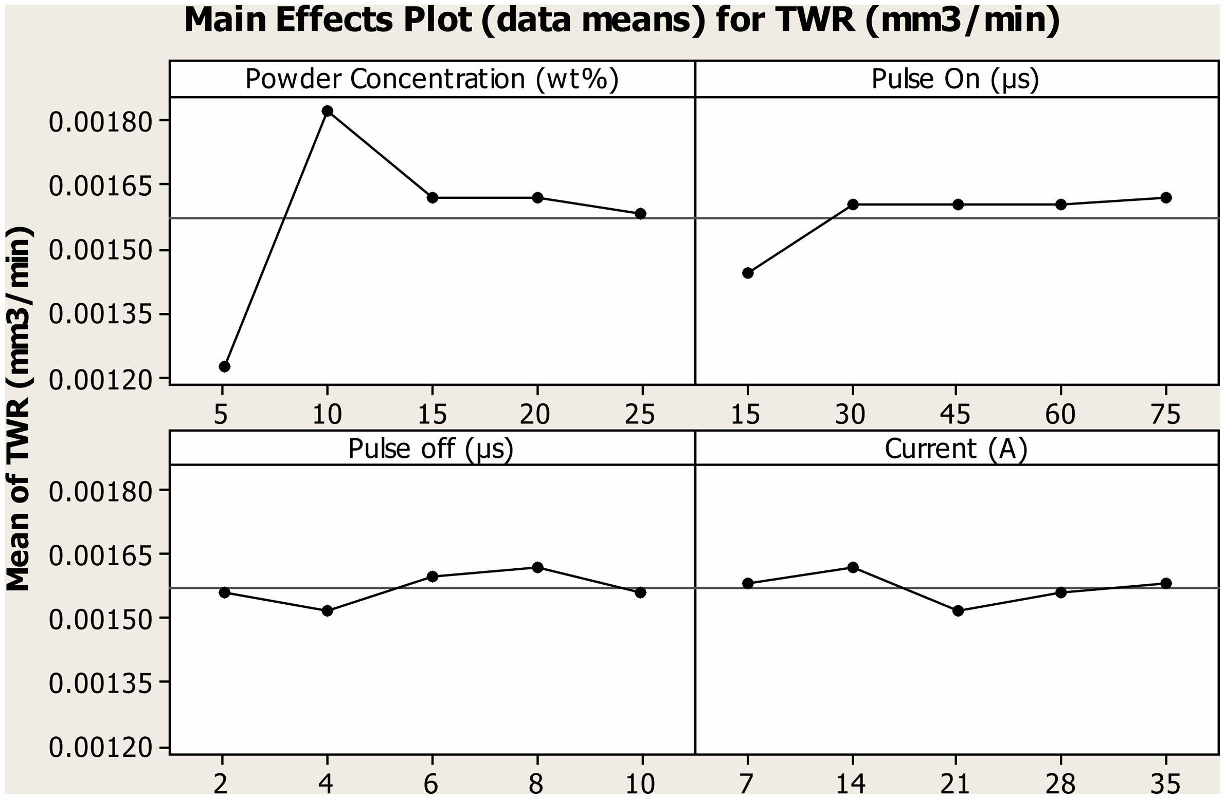
The impact of various process parameters on the TWR under Cu incorporated PMEDM was depicted in the Fig. 8. In EDM, machining occurred by means of melting and vaporization [33], hence materials removed from both the work piece and the electrode material. The objective of the EDM industry was to increase the MRR and to reduce the TWR. At 5 g/l PMEDM condition, least mean TWR of 0.00122 mm3/min was attained. It was attributed to the fact at 5 g/l dielectric condition, incorporated particles absorbed the most of generated heat and evaporated. It reduces the heat transfer to the work piece as well as to tool material, hence TWR reduces. At the concentration of 10 g/l, it facilitates the bridging effect hence TWR increases. When the concentration exceeds beyond 10 g/l, TWR reduces owing to the machined debris densification. TWR slightly increases from 0.0014 mm3/min to 0.0016 mm3/min when there is raise in Pon from 15 µs to 75 µs. At higher Pon, generated heat was sustained inside the spark gap for longer duration which eroded more tool materials hence TWR increases.
With the upsurge in Poff from 2 µs to 10µs, very slight variation in TWR was observed. As the off time was primarily for flushing of machined debris, deviation in Poff has very little impact on TWR. From the swift in upper parametric level to the lower parametric level TWR ranges between 0.0015 mm3/min to 0.0016 mm3/min. The increase in current generates heat of very high intensity which ultimately increases the both the MRR and TWR [34]. But with the incorporation of powder particles TWR of composite tool hangs around 0.0015 mm3/min, irrespective of the parametric value of current. Experimental results of MRR confirms that it increases with raise in current. By comparing both the results it was conformed that most of the generated heat was transferred to the work piece.
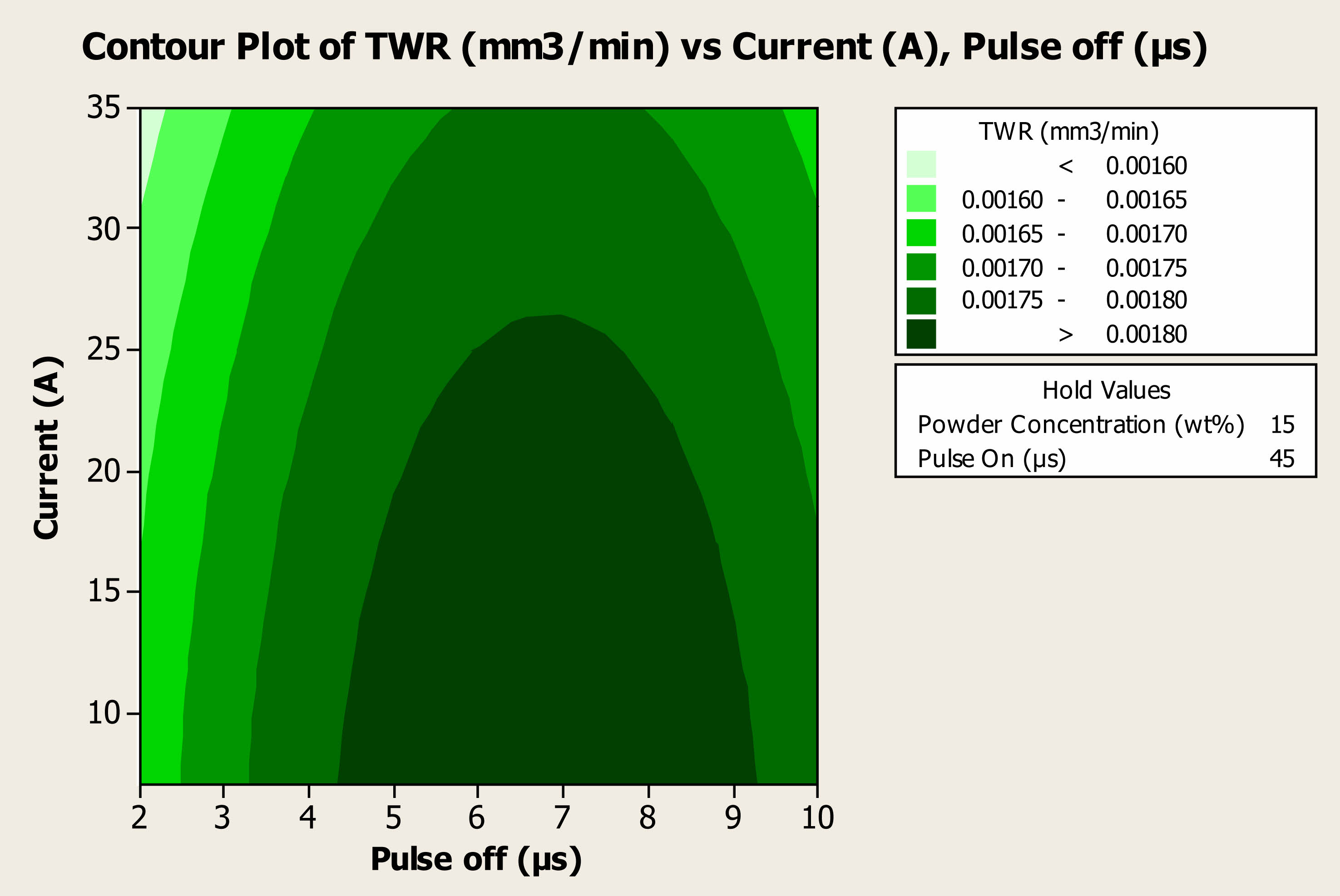
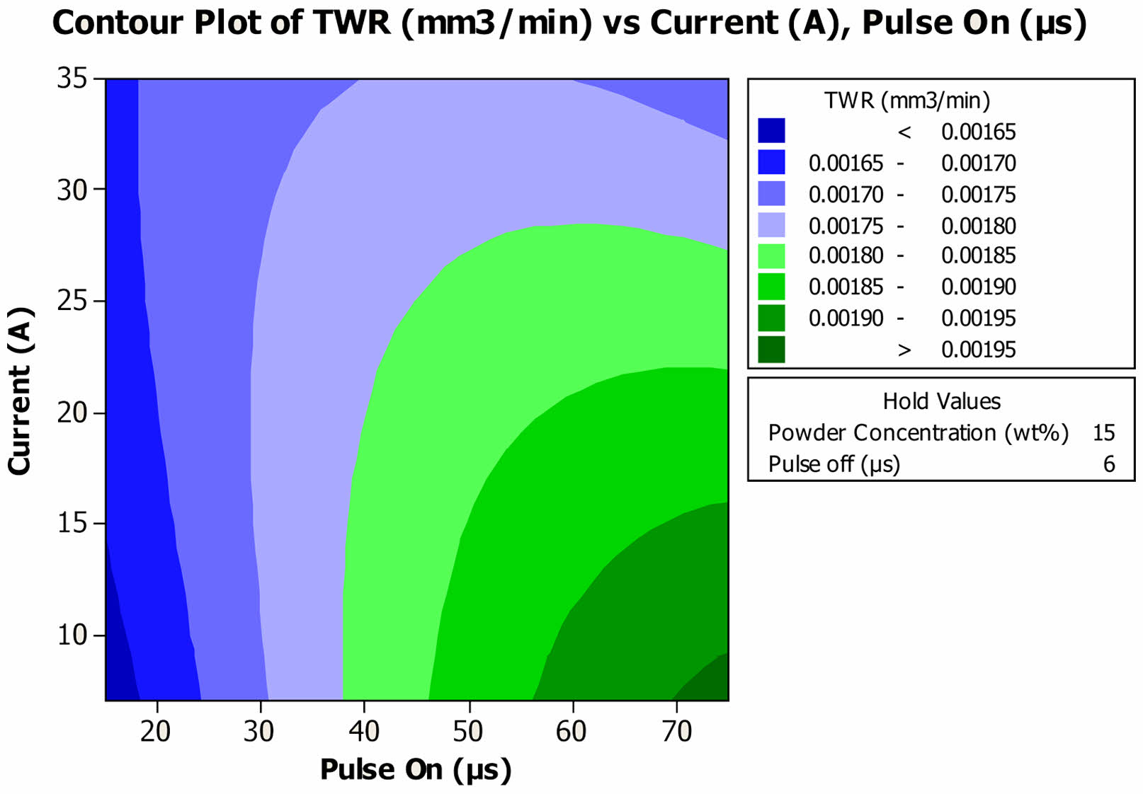
For the lower parametric value of 7A current, 0.00166 mm3/min and 0.00176 mm3/min of TWR was attained was attained for 2 µs and 10 µs Poff time as depicted in the Fig. 9. The maximum TWR of 0.00184 mm3/min was recorded when Poff was tunes at 6 µs. For higher parametric value of 35A current, TWR reduces to 0.00158 mm3/min and 0.00168 mm3/min for 2 µs and 10 µs Poff respectively. The results confirmed that heat generated was transferred to the work piece, hence attained the objective of the EDM industry. In case of current and Pon, a very high TWR of 0.00196 mm3/min was documented for the values of 7A and 75 µs as shown in Fig. 10. At 75 µs Pon, with upsurge in current TWR drastically reduces to 0.0017 mm3/min. The reduction in TWR was attributed to the fact, owing to the bridging effect gap between the tool and the wok piece increases which reduces the intensity of heat transferred to the tool material.
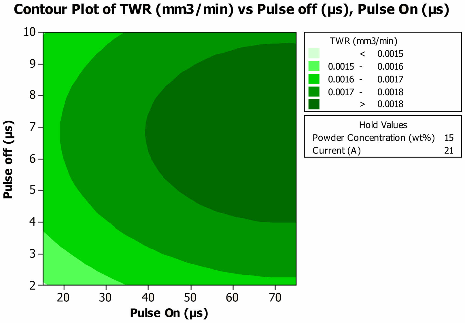
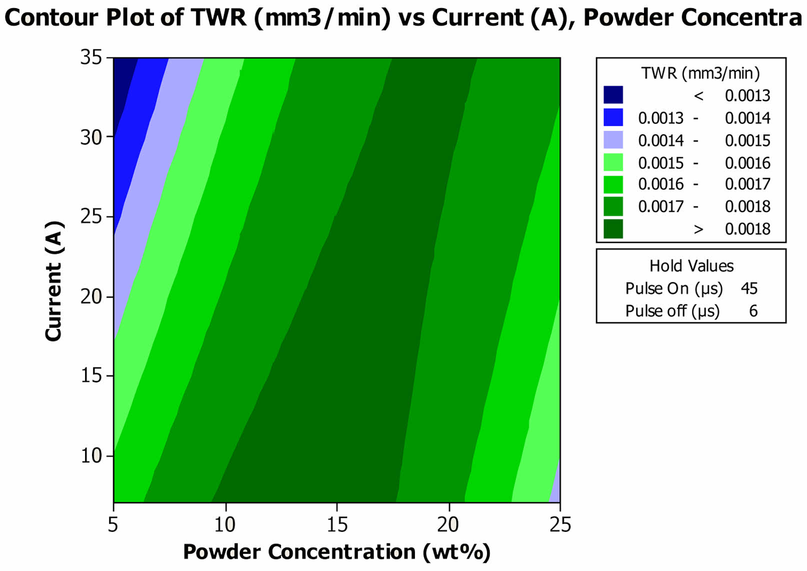
For the lower parametric Pon and Poff values of 10 µs and 2 µs, a least TWR of 0.00149 mm3/min was observed as shown in Fig. 11 and it was increased to 0.16 mm3/min for 10 µs Poff. When the Pon was tuned to the parametric level of 75 µs, a maximum TWR of 0.00190 mm3/min was noted for 7 µs Poff. In the experimental result of MRR, for same parametric condition low MRR was noted, hence it was clear at this parametric setting more heat was transferred to the tool materials. The interaction impact of powder concentration and current was depicted in the Fig. 12. At the powder concentration of 5 g/l, TWR reduces with increase in current. It was observed that the TWR of 0.00163 mm3/min and 0.00121 mm3/min was attained, for 7A and 35A current respectively. When the powder concentration was 25 g/l, at lower parametric value of 7A current, 0.00142 mm3/min was observed and it was raised to 0.00172 mm3/min for the 35A current. A maximum TWR of 0.00183 mm3/min was observed, for the current of 7A at the powder concentration of 15 g/l.
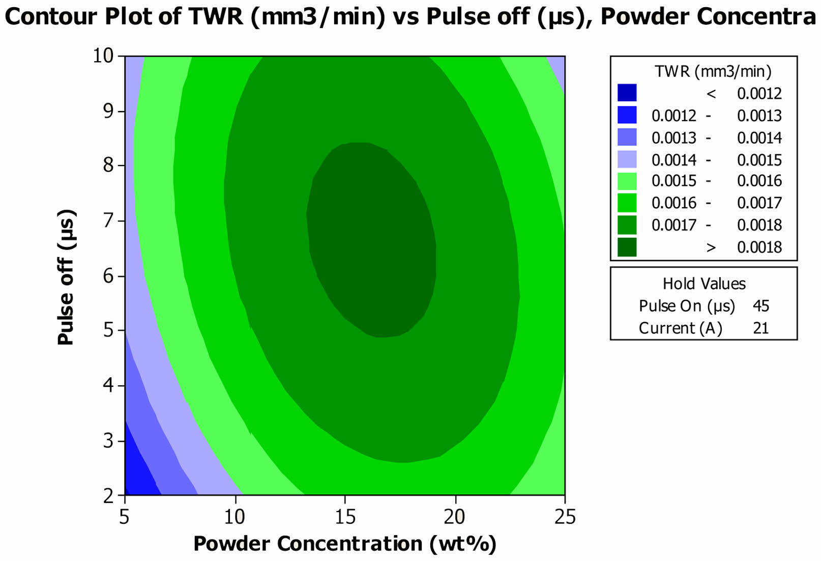
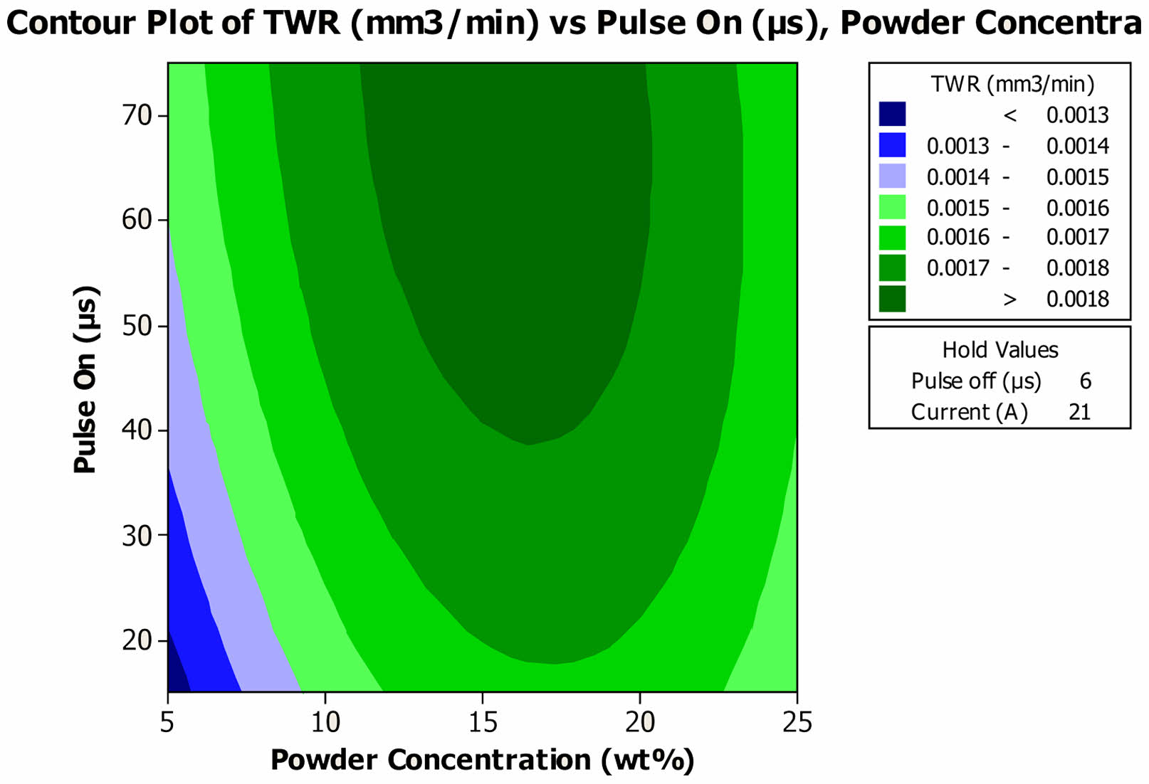
At 5 g/l of Cu incorporated medium, a least TWR of 0.00119 mm3/min was achieved for 2 µs Poff and it was increased to 0.00144 mm3/min for Poff time of 10 µs as shown in Fig. 13. At higher powder concentration of 25 g/l, TWR reduces from 0.0015 mm3/min to 0.0014 mm3/min with raise in Pon from 2 µs to 10 µs. When 15 g/l of Cu particles were incorporated, TWR of 0.00182 mm3/min was recorded when Poff was tuned at 7 µs. In case of Pon and powder concentration, TWR increases with raise in Pon, irrespective of the amount of powder mixed in the dielectric medium as shown in the Fig. 14. The low TWR of 0.00121 mm3/min was achieved when the Pon was tuned at 10 µs in 5 g/l incorporated medium. At the same time a maximum TWR of 0.00186 mm3/min was noted at 15 g/l PMEDM condition and Pon of 75 µs.
TWR = 0.000363856 + 8.95828E-05 Powder Concentration (wt%) + 1.44846E-05 Pulse On (µs) + 0.000138400 Pulse off (µs) - 9.67439E-06 Current (A) - 2.91739E-06 Powder Concentration (wt%)* Powder Concentration (wt%) - 5.66548E-08 Pulse On (µs)*Pulse On (µs) - 7.88754E-06 Pulse off (µs)*Pulse off (µs) - 8.15784E-08 Current(A) * Current (A) - 1.54504E-07 Powder Concentration (wt%)*Pulse On (µs) - 2.06250E-06 Powder Concentration (wt%)*Pulse off (µs) + 1.22394E-06 Powder Concentration (wt%)*Current (A) - 1.87031E-07 Pulse On (µs)* Current (A) (2)
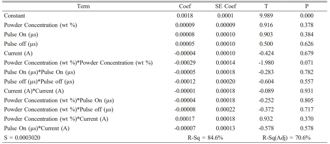
Table 7 displays the predicted regression coefficient. The parameters with a P value less than 0.05 were the most relevant factor since the experimental runs were designed with a 95% confidence level. Eq. (2) depicts the mathematical model for forecasting TWR. As shown in Table 8, the most significant factors that have an influence on TWR are Powder concentration, current and interaction of pulse off time and pulse on time.
Surface Roughness
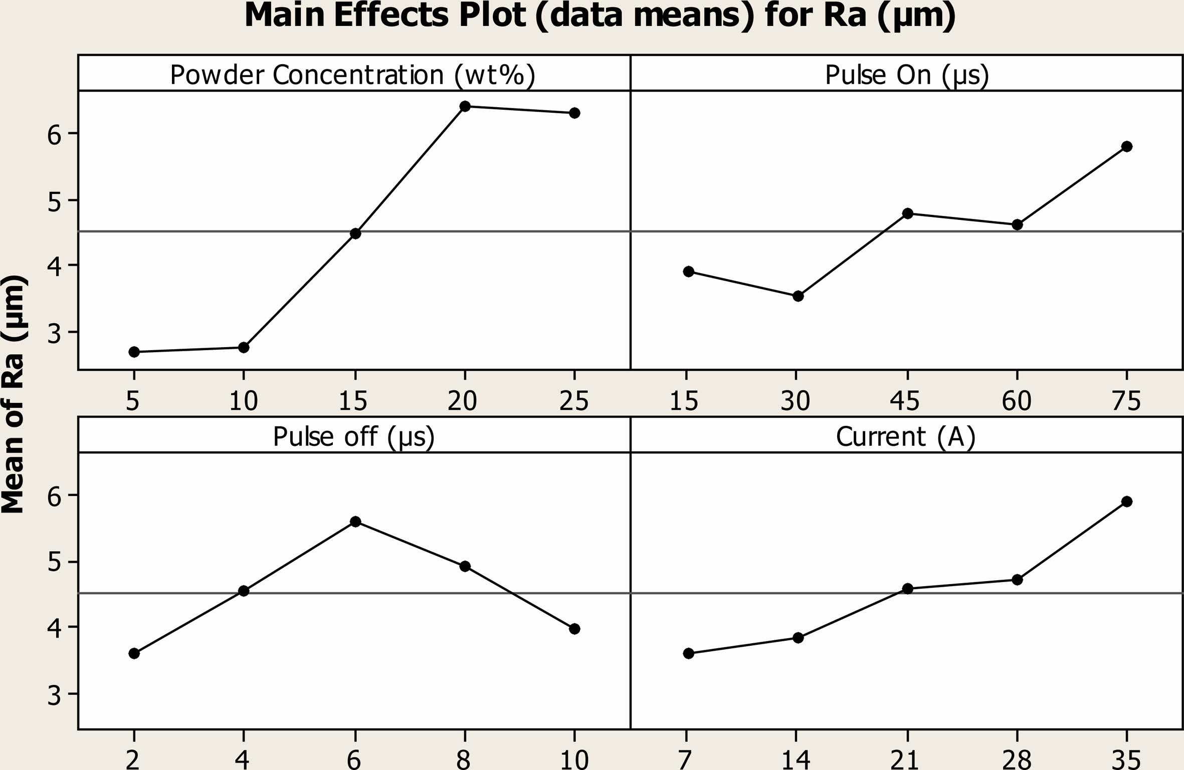
The influence of process parameters on Ra of Ti alloy under Cu powder incorporated PMEDM was depicted in the Fig. 15. The minimum Ra value of 2.69 µm was attained when 5 g/l of Cu was incorporated in the dielectric fluid. It was 2.17 times worser than the unmixed medium. With increase in powder concentration, Ra becomes more worser, at 25 g/l concentration mean Ra was increased to 6.29 µm. The increase in Ra value was attributed by the following facts that when voltage was applied, the incorporated particles absorb the heat and redeposited over the surface which reduce the surface quality [35]. At higher powder concentration, more heat was generated hence more volume of material was removed from the surface. Because of the machined debris these particles are not completely flushed away from the machined gap which increases the Ra value.
Ra increases with raise in Pon and maximum Ra of 5.81 µm was recorded for the Pon time of 75 µs. It was evident that the generated heat was hold inside the machined gap for longer duration of time. This facilitates the melting and evaporation of materials, as discussed earlier large volume of materials were removed from the surface. These machined materials were not flushed away completely and redeposited over the surface; hence machined surface quality reduces. The Ra value increases with raise in current, at higher current heat of very high intensity was produces which creates cracks and craters on the surface leads to reduction in surface quality. Ra increases with raise in Poff until a saddle point of 6 µs thereafter it declines. As observed in the experimental results of MRR and TWR, more materials were machined at the Poff of 6 µs. It was confirmed that the maximum heat was generated at this Poff value which forms un-eventuality on the surface leads to reduction of Ra.
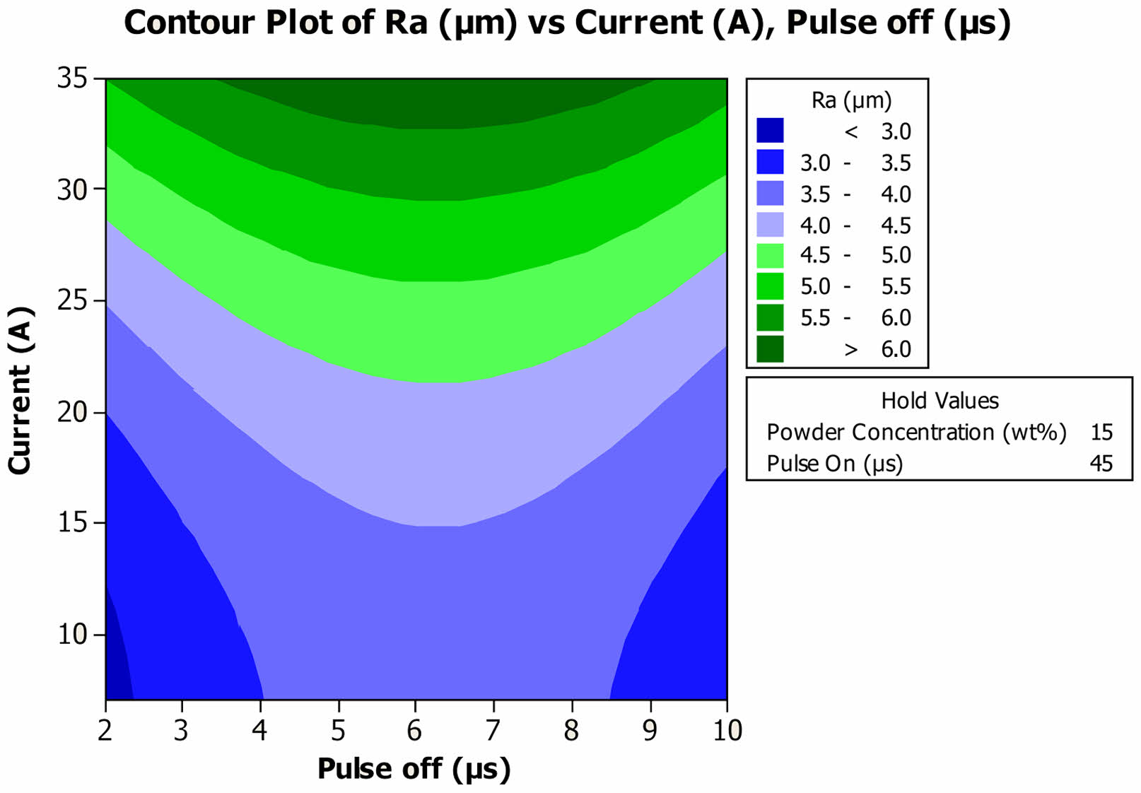
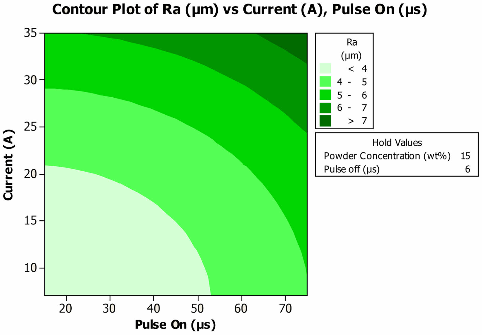
The interaction impact of distinct process on Ra of the Ti alloy under Cu mixed PMEDM. At lower value of 7A current, for the Poff time of 2 µs least Ra value of 2.87 m was attained and it was slightly raised to 3.20 µm for the Poff value of 10 µs. When the value of current was increased to 35A, Ra of 5.49 µm and 5.71 µm was attained for 2 µs and 10 µs respectively as shown in Fig. 16. The Ra becomes even worser (6.38 µm) when the Poff was tuned at 6 µs. The results showed that surface become worser when machined at higher parametric value of current, regardless of the value of Poff. When the Pon and current were tuned at lower parametric value of 7A and 10s, Ra of 3.23 m was achieved and it was drastically increased to 7.51 µm when the values were shifted to upper parametric level i.e 35A current and 75 µs Pon as shown in Fig. 17. At 7A current with raise in Pon, Ra gradually increases and reaches a maximum of 4.95 µm at 10 µs.
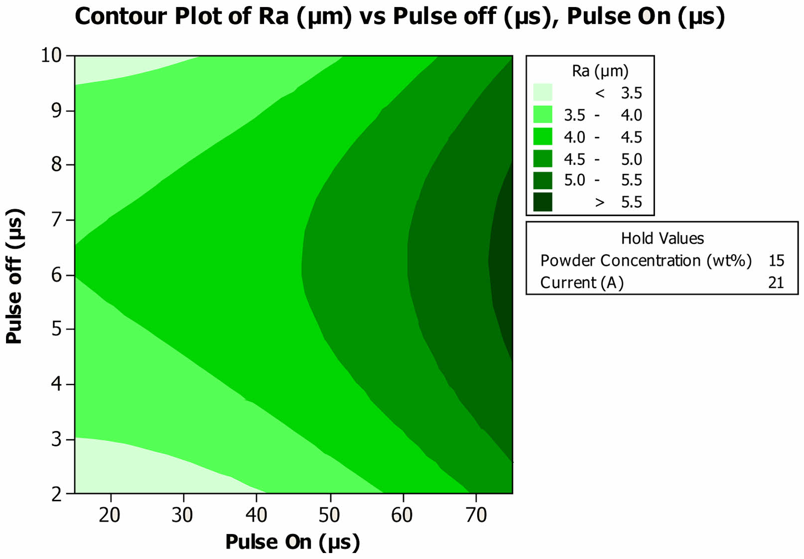
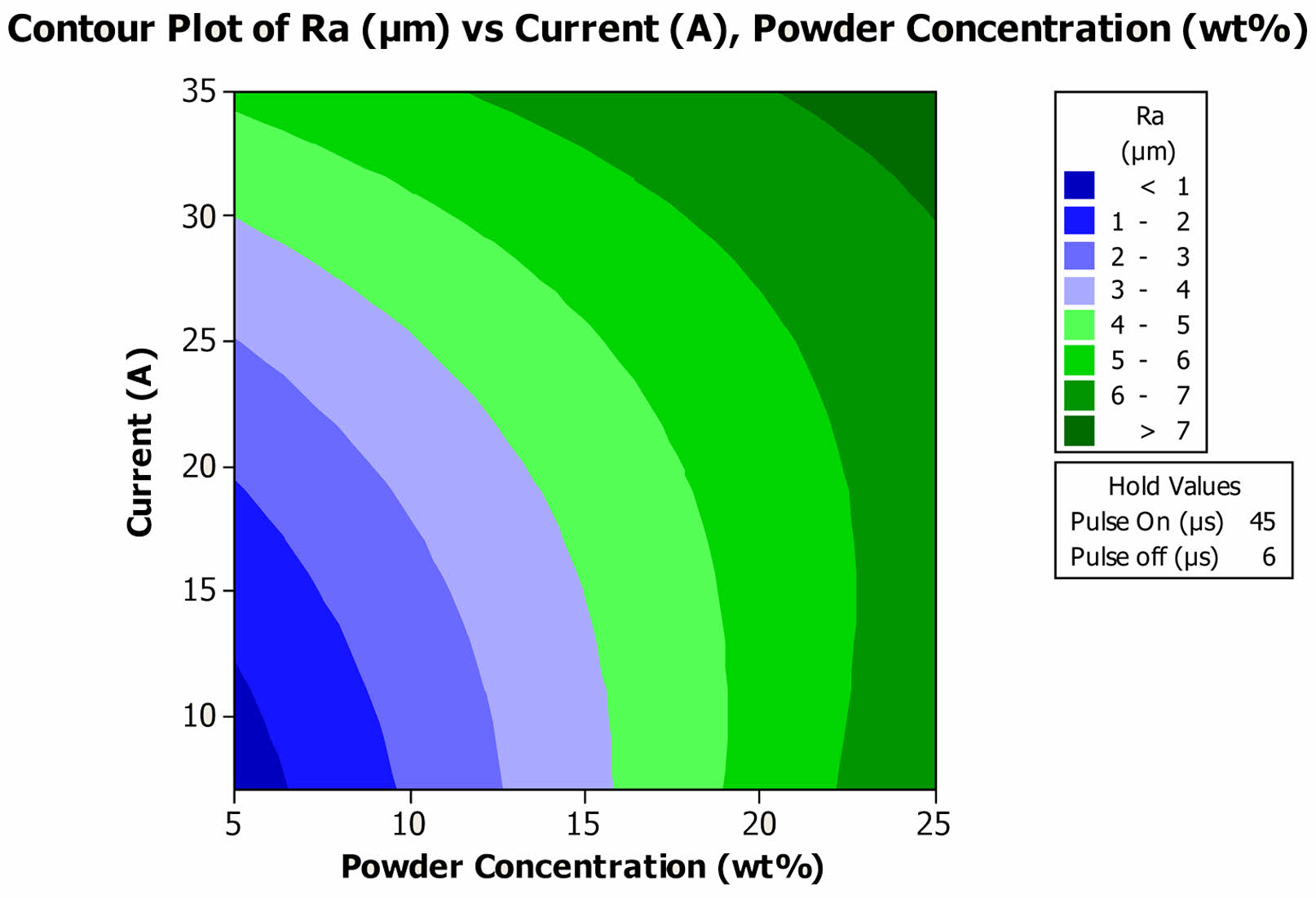
The interaction impact of Pon and Poff were depicted in the Fig. 18. Ra was 3.13 µm for 2 µs, 4.00 µm for 6 µs, and 3.31 µm for 10 µs, when the Pon was tuned at lower parametric value of 10 µs as shown in Fig. 18. When the Pon was increased to 75s quality of the surface quality became worser. Ra was 4.79 µm for 2 µs, 5.64 µm for 6 µs, and 4.97 µm for 10 µs, when the Pon was tuned at lower parametric value of 10µs. The interaction impact of current and powder concentration was depicted in the Fig. 19. At 5 g/l Cu incorporated dielectric medium, specimens machined with the current of 7A exhibit the least Ra of 0.49 µm and it was radically increased to 5.16 µm when the value of current increased to 35A. For the powder concentration pf 25 g/l, Ra of 6.83 µm and 7.45 µm was attained for the current of 7A and 35A respectively. The result revealed that the increase in the concentration of powder and current has significant impact on the Ra of the composites.
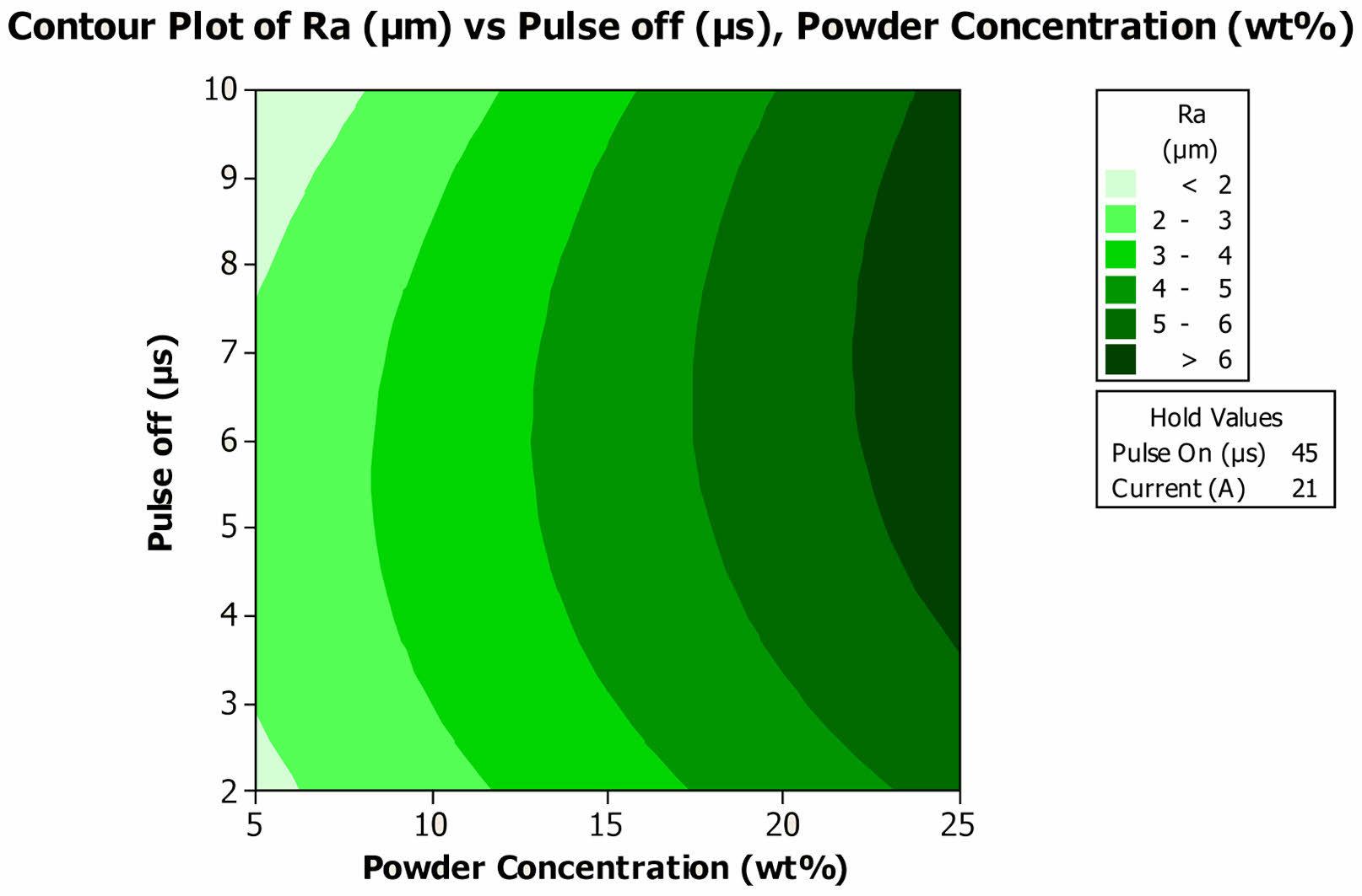
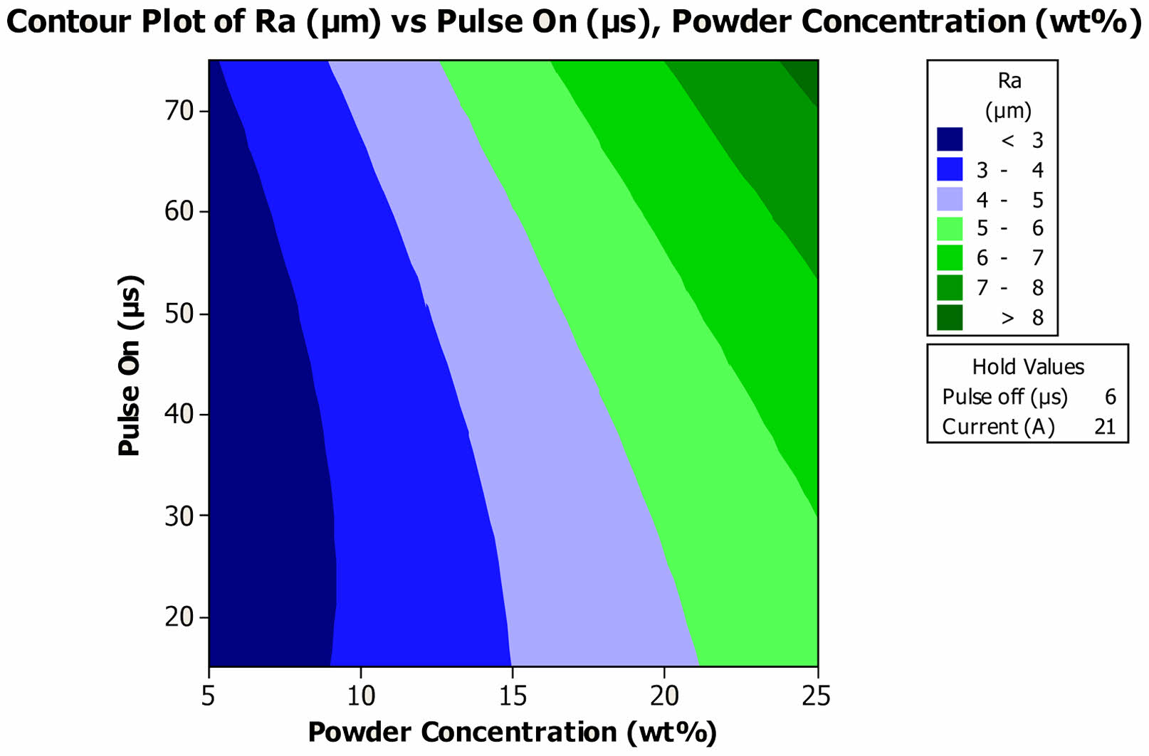
In case of interaction impact of Poff and powder concentration, Ra of 1.77 µm was attained for the 2s Poff and 5 g/l Cu concentration and it was degraded to the 6.30 m when the concentration and Poff was increased to 25 g/l and 10s respectively as shown in Fig. 20. Regardless of the Poff time Ra value increases with raise in powder concentration. Machined with lower Pon and at 5 g/l Cu incorporated dielectric medium results in machined surface of lower Ra value of 2.30 µm. When the Pon was tuned to 75 µs quality of the surface was worsen to 8.21 µm at the 25 g/l PMEDM condition as shown in the Fig. 21.
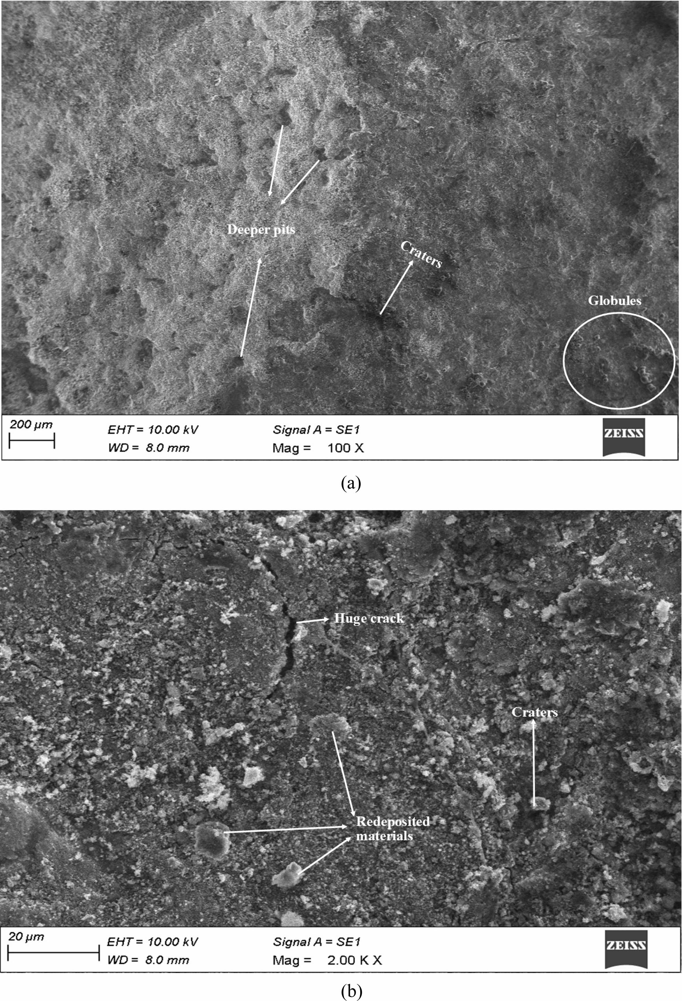
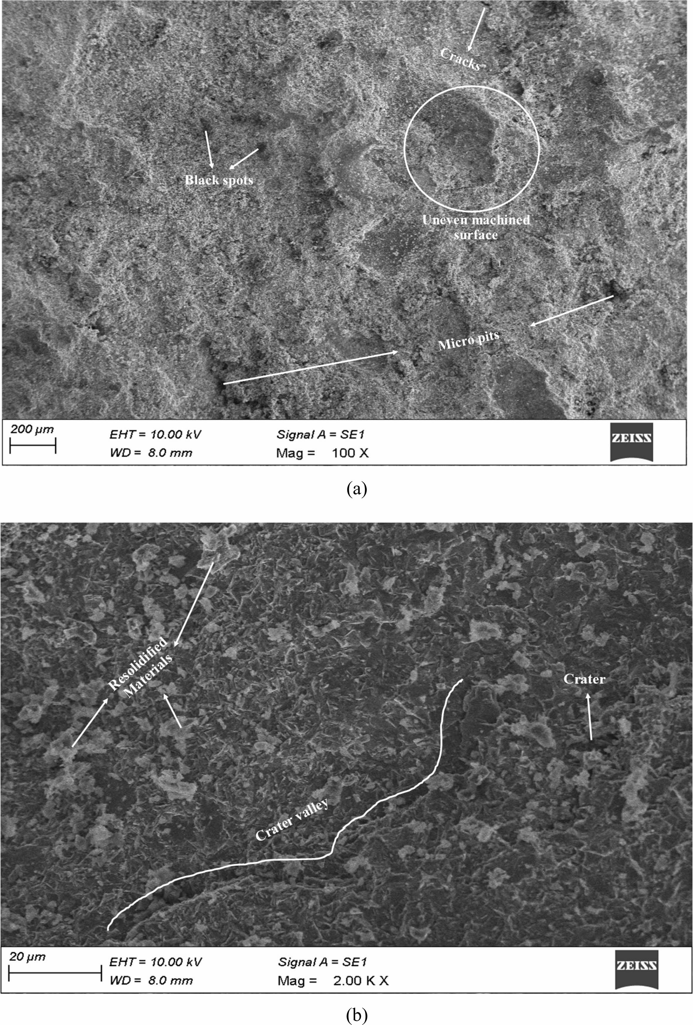
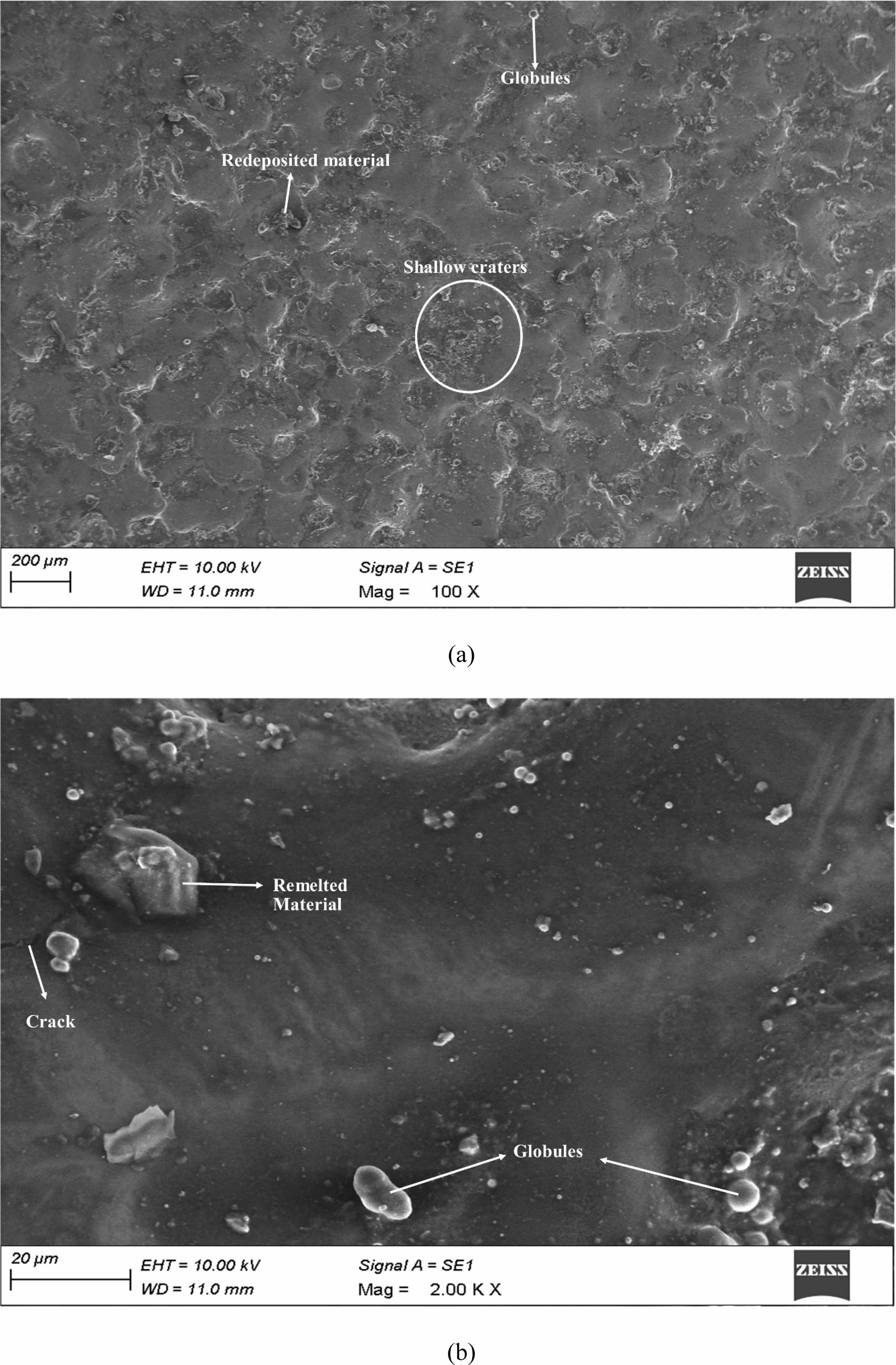
At a high concentration of 25 g/l, the surface exhibited deep pits, craters, and globules, indicative of excessive heat generation and inadequate flushing of machined debris. This resulted in a rougher surface with a mean Ra of 6.29 µm. The higher particle density at 25 g/l created a barrier effect, causing more intense and localized heating, led to the pronounced surface irregularities. When the concentration was reduced to 10 g/l, there was an improvement in surface texture. The size of pits and cracks decreased, and some carbon content deposition from the dielectric fluid was observed. The surface roughness improved with a reduced Ra, though not significantly lower than the highest concentration, indicating a transition phase in surface quality enhancement. At the lowest concentration of 5 g/l, the surface quality improved notably. Minimal cracks and redeposited material were observed, resulting in a smoother surface texture. The Ra achieved at this concentration was significantly lower, with a minimum value of 2.69 µm. This improvement was due to better heat dissipation and more effective particle flushing, preventing excessive heat generation and reducing surface irregularities. At high Cu powder concentration (25 g/l), inefficient flushing leads to excessive localized heating, causing deep pits and globules. As the concentration decreases to 10 g/l, flushing efficiency improves, reducing heat concentration and thus diminishing the size of pits and cracks. At the lowest concentration (5 g/l), optimal flushing ensures effective heat dissipation and debris removal, resulting in minimal surface defects and the lowest Ra. Therefore, better flushing and heat distribution at lower concentrations enhance surface quality by preventing heat accumulation and promoting uniform machining.
Ra = -2.23897 + 0.250953 Powder Concentration (wt%) - 0.0332025 Pulse On (µs) +0.462245 Pulse off (µs)+0.0820721 Current (A)-5.74878E-04 Powder Concentration (wt%)*Powder Concentration (wt%)+0.000405261 Pulse On (µs)*Pulse On (µs) - 0.0488079 Pulse off (µs)*Pulse off (µs) + 0.00303717 Current (A)*Current (A) + 0.00176005 Powder Concentration (wt%) * Pulse On (µs) + 0.00987563 Powder Concentration (wt%)*Pulse off (µs) - 0.00737333 Powder Concentration (wt%)* Current (A) - 9.64850E-05 Pulse On (µs)*Current (A) (3)
Table 9 displays the predicted regression coefficient. The parameters with a P value less than 0.05 were the most relevant factor since the experimental runs were designed with a 95% confidence level. Eq. (3) depicts the mathematical model for forecasting Ra. As shown in Table 10, the most significant factors that have an influence on Ra are powder concentration, pulse on time, current and interaction of pulse on time and current.
Surface topography
The surface topography of the titanium alloy machined under Cu mixed dielectric was investigated with the aid of SEM. When machined with 25 g/l Cu powder mixed environment, the surface texture showed globules, craters and deeper pits as depicted in the Fig. 22a. When machined under high concentration of Cu powder incorporated dielectric medium, it generates extreme heat which struck on the work piece and formed deeper pits and craters, hence Ra reduces. Owing to the machined debris densification, insufficient flushing of particles occurred results in formation of globules. At higher magnification huge crack and craters were evident as shown in the Fig. 22b, the width of the crack measures around 2 µm. The texture also witnessed lot of redeposited materials over the surface which confirms that the flushing was inadequate.
When machined in the 10 g/l powder mixed dielectric environment, the surface texture showed micro pits and cracks as shown in Fig. 23a. The size of the cracks and pits were reduced; hence it exhibits better Ra. Lot of black spots were also observed on the surface which was the carbon content deposited from the dielectric fluid. The texture also reveals uneven machined surface which showed that the generated heat was not distributed uniformly. At higher magnification lot of resolidified layer materials were observed on the surface as depicted in the Fig. 23b. It also displayed the craters and shallow crater valley of length measures around 100 µm.
With further reduction in concentration of Cu powder to 5 g/l enhances the quality of the surfaces. No cracks were observed on the surface and quantity of redeposited layer over the machined surface reduced, hence quality of the surface improves. The shallow craters were observed and tiny globules formed because of inadequate flushing as shown in the Fig. 24a. At higher magnification surface texture revealed globules and remelted layers. The crack with approximate width of 0.5µm was observed as shown in the Fig. 24b. Owing to the reduction in the length of the width quality of the surface increases in comparison to surface produced under 25 g/l dielectric condition.
The formation of cracks on machined surfaces under varying Cu powder concentrations was influenced by thermal stresses, cooling rates, and material properties. At higher Cu powder concentrations (e.g., 25 g/l), the dielectric medium contains more conductive particles, leading to enhanced sparking intensity and localized heating. This intense heat generation induces significant thermal stresses within the material, which are not uniformly dissipated due to inadequate flushing. As a result, the surface undergoes rapid expansion and contraction, forming wider cracks, typically around 2 µm. The high temperature gradients exacerbate these stresses, promoting the initiation and propagation of cracks. When the Cu powder concentration is reduced to 10 g/l, there is an improvement in flushing efficiency, which helps in better heat dissipation and reduces the intensity of thermal stresses. Consequently, the cracks formed are narrower, approximately 1 µm, as the thermal gradients are less severe and the material experiences more controlled cooling. The presence of a moderate amount of Cu particles still contributes to some redeposition and uneven cooling, but the overall effect is less detrimental compared to the higher concentration. At the lowest concentration of 5 g/l, the flushing efficiency is optimal, ensuring effective removal of debris and more uniform heat distribution. The reduced concentration of conductive particles leads to lower sparking intensity and more even thermal distribution, minimizing thermal stresses. As a result, the cracks observed are the narrowest, around 0.5 µm. This condition allows for better-controlled cooling rates and reduces the likelihood of significant surface defects.
The redeposited materials primarily consisted of copper particles from the dielectric medium, interspersed with carbon elements. Morphologically, these materials appeared as small globules and irregular patches scattered across the surface. The resolidified layers were thin and uneven, indicating rapid cooling and solidification of molten material during machining. The presence of these redeposited materials and resolidified layers significantly impacted surface roughness and overall quality. The globules and irregular patches created by redeposited materials increased surface roughness (Ra), contributing to a less smooth finish. Additionally, the uneven resolidified layers led to micro-cracks and brittle zones, further degrading surface integrity. Larger cracks increase the risk of crack propagation, reducing the fatigue life and structural strength of the machined component.
MEIOT
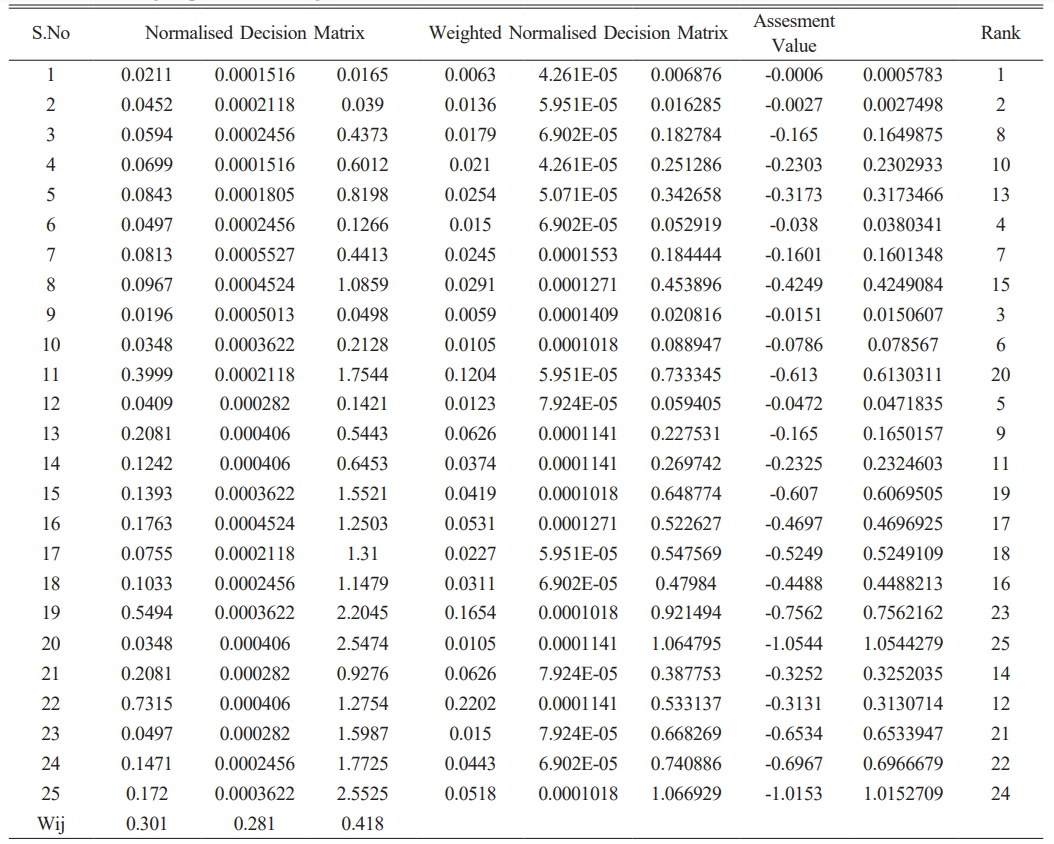
The experimental work was optimized using the MEIOT optimization technique. The first step was the normalising the beneficiary and non – beneficiary attributes. The weight of each criterion was multiplied to the normalised value to form weighted normalised decision matrix. The assessment value and the rank were calculated by the MOORA technique as shown in the Table 11. The top five ranked parametric combination were selected for individual comparison. The concordance and discordance values were computed by comparing performance of each parametric combination. The optimal parameters were calculated by means of incorporating concordance and discordance value as shown in the Table 12. Ensuring consistent Cu powder distribution in the dielectric medium is critical, as any variation can impact surface quality and machining precision. Scaling up also requires maintaining efficient flushing systems to prevent debris accumulation and thermal stress. The cost of high-quality Cu powder and advanced EDM equipment might be significant, affecting overall cost-effectiveness. Additionally, training personnel to handle and optimize these parameters is essential for achieving desired outcomes consistently.
|
Fig. 1 Influence of various process parameters on MRR under Cu PMEDM. |
|
Fig. 2 Impact of current (A) and Pulse off time (µs) on MRR of Titanium alloy in Cu PMEDM. |
|
Fig. 3 Impact of current (A) and Pulse on time (µs) on MRR of Titanium alloy in Cu PMEDM. |
|
Fig. 4 Impact of Pulse on time (µs) and Pulse off time (µs) on MRR of Titanium alloy in Cu PMEDM. |
|
Fig. 5 Impact of Current (A) and powder concentration on MRR of Titanium alloy in Cu PMEDM. |
|
Fig. 6 Impact of Pulse off time (µs) and powder concentration on MRR of Titanium alloy in Cu PMEDM. |
|
Fig. 7 Impact of Pulse on time (µs) and powder concentration on MRR of Titanium alloy in Cu PMEDM. |
|
Fig. 8 Influence of various process parameters on TWR under Cu PMEDM. |
|
Fig. 9 Impact of current (A) and Pulse off time (µs) on TWR under Cu PMEDM. |
|
Fig. 10 Impact of current (A) and Pulse on time (µs) on TWR under Cu PMEDM. |
|
Fig. 11 Impact of Pulse on time (µs) and Pulse off time (µs) on TWR under Cu PMEDM. |
|
Fig. 12 Impact of Current (A) and powder concentration on TWR under Cu PMEDM. |
|
Fig. 13 Impact of Pulse off time (µs) and powder concentration on TWR under Cu PMEDM. |
|
Fig. 14 Impact of Pulse on time (µs) and powder concentration on TWR under Cu PMEDM. |
|
Fig. 15 Influence of various process parameters on Ra under Cu PMEDM. |
|
Fig. 16 Impact of current (A) and Pulse off time (µs) on Ra under Cu PMEDM. |
|
Fig. 17 Impact of current (A) and Pulse on time (µs) on Ra under Cu PMEDM. |
|
Fig. 18 Impact of Pulse on time (µs) and Pulse off time (µs) on Ra under Cu PMEDM. |
|
Fig. 19 mpact of Current (A) and powder concentration on Ra under Cu PMEDM. |
|
Fig. 20 Impact of Pulse off time (µs) and powder concentration on Ra under Cu PMEDM. |
|
Fig. 21 Impact of Pulse on time (µs) and powder concentration on Ra under Cu PMEDM. |
|
Fig. 22 Surface topography of specimen machined with 25 g/l Cu mixed di-electric medium (a) at 100X (b) at 2000X. |
|
Fig. 23 Surface topography of specimen machined with 10g/l Cu mixed di-electric medium (a) at 100X (b) at 2000X |
|
Fig. 24 Surface topography of specimen machined with 5g/l Cu mixed di-electric medium (a) at 100X (b) at 2000X. |
Ti alloy exhibit high MRR of 3.2 mm3/min under Cu powder incorporated dielectric fluid owing to the bridging effect. For the Pon parametric value of above 60 µs, machined under the Cu PMEDM concentration of 15 g/l, MRR reduces drastically irrespective of the other process parameters. ANOVA table reveals that powder concentration and current were the two most influential process parameter which impacts the MRR.
Cu particles absorbed the majority of the heat created and evaporated. It minimises heat transmission to both the work piece and the tool material, lowering TWR. It promotes the bridging effect at a concentration of 10 g/l, resulting in an increase in TWR.
The fact that when voltage was applied, the integrated particles absorbed the heat and redeposited across the surface, reducing the surface quality, was linked to the increase in Ra value. More heat was created at greater powder concentrations, which resulted in more material being removed from the surface. These particles are not entirely drained out from the machined gap due to the machining debris densification, which raises the Ra value.
Cracks, craters, globules and re-solidification of materials were observed on the machined surface morphology. The optimized parameters under MEIOT technique were 45 µs Pon, 6 µs Poff and 7A current under 5 g/l Cu powder incorporated dielectric medium.
- 1. D.K. Rajak, D.D. Pagar, R. Kumar, and C.I. Pruncu, J. Mater. Res. Technol. 8[6] (2019) 6354-6374.
-

- 2. A.K. Sharma, R. Bhandari, A. Aherwar, R. Rimašauskienė, and C. Pinca-Bretotean, Mater. Today: Proc. 26 (2020) 2419-2424.
-

- 3. R. Casati, and M. Vedani, Metals, 4[1] (2014) 65-83.
-

- 4. A. Vishnu and M. Subramanian, J. Ceram. Process. Res. 25[2] (2024) 168-177.
-

- 5. E. Candan, H. Ahlatci, and H. Çı̈menoğlu, Wear 247[2] (2001) 133-138.
-

- 6. J. Hashim, L. Looney, and M.S.J. Hashmi, J. Mater. Process. Technol 92(1999) 1-7.
-

- 7. T.L. Banh, H.P. Nguyen, C. Ngo, and D.T. Nguyen, Proc. Inst. Mech. Eng., Part E. 232[3] (2018) 281-298.
-

- 8. E. Unses and C. Cogun. Vestnik/Journal of Mechanical Engineering 61[6] (2015).
-

- 9. C. Prakash, H.K. Kansal, B.S. Pabla, and S. Puri, Mater. Manuf. Processes. 32[3] (2017) 274-285.
-

- 10. T. Suresh, P. Suresh, and M. Prabu. J. Ceram. Process. Res. 25[2] (2024) 192-201.
-

- 11. S. Kumar, R. Singh, A. Batish, and T.P. Singh. Proc. Inst. Mech. Eng., Part E 231[2] (2017) 271-282.
- 12. S. Kumar, R. Singh, A. Batish, T.P. Singh, and R. Singh, J. Braz. Soc. Mech. Sci. Eng. 39[7] (2017) 2635-2648.
-

- 13. M. Bhaumik and K. Maity. Eng. Sci. Technol. 21[3] (2018) 507-516.
-

- 14. S. Dewangan, C.K. Biswas, and S. Gangopadhyay, Mater. Manuf. Processes. 29[11-12] (2014) 1387-1394.
-

- 15. A.K. Sahu and S.S. Mahapatra, Proc. Inst. Mech. Eng., Part C. 235[11] (2021) 1992-2007.
-

- 16. X. Wang, C. Li, H. Guo, S. Yi, L. Kong, and S. Ding. J. Manuf. Processes. 60 (2020) 37-47.
-

- 17. V. Penugonda, S.S. Babu, and B.V. Kumar, J. Ceram. Process. Res. 24[2] (2023) 250-256.
-

- 18. J. Kumar, T. Soota, S.K. Rajput, and K.K. Saxena, Mater. Manuf. Processes. 1-11 (2021).
-

- 19. S. Ramesh and M.P. Jenarthanan. World J. Eng. 15[2] (2018) 205-215.
-

- 20. M. Bhaumik and K. Maity, Silicon 11[1] (2019) 187-196.
-

- 21. F. Rajabinasab, V. Abedini, M. Hadad, and R. Hajighorbani, Proc. Inst. Mech. Eng., Part E. 234[4] (2020) 308-317.
-

- 22. M.P. Jahan and F. Alavi. J. Mater. Eng. Perform. 28[6] (2019) 3517-3530.
-

- 23. R. Manivannan and M.P. Kumar. J. Mech. Sci. Technol. 30[1] (2016) 137-144.
-

- 24. P. Senthil, S. Vinodh, and A.K. Singh, Int. J. Mach. Mach. Mater. 16[1] (2014) 80-94.
-

- 25. S. Dewangan, S. Gangopadhyay, and C.K. Biswas. Meas. 63(2015) 364-376.
-

- 26. A.B. Gurcan and T.N. Baker. Wear 188[1-2] (1995) 185-191.
-

- 27. M. Bannister. Composites, Part A. 32[7] (2001) 901-910.
-

- 28. I.B. Deshmanya and G.K. Purohit, J. Compos. Mater. 46[26] (2012) 3247-3253.
-

- 29. C. Kannan and R. Ramanujam, J. Adv. Res. 8[4] (2017) 309-319.
-

- 30. L. Singh, B. Ram, and A. Singh, Int. J. Pure Appl. Res. Eng. Technol. 2[08] (2013) 375-383.
- 31. B. Thamaraikannan, A.S.F. Britto, S. Senthilraja, and R. Rajkumar, J. Ceram. Process. Res. 24[3] (2023) 415-421.
-

- 32. C. Balázsi, Z. Kónya, F. Wéber, L.P. Biró, and P. Arató. ater. Sci. Eng. 23[6-8] (2003) 1133-1137.
-

- 33. B. Zhang, R.W. Fu, M.Q. Zhang, X.M. Dong, P.L. Lan, and J.S. Qiu, Sens. Actuators, B. 109[2] (2005) 323-328.
-

- 34. M.C. Şenel, M. Gürbüz, and E. Koc. Composites, Part B. 154 (2018) 1-9.
-

- 35. S. Wang, Z. Tan, Y. Li, L. Sun, and T. Zhang, Thermochim. Acta. 441[2] (2006) 191-194.
-

 This Article
-
2024; 25(6): 1069-1086
Published on Dec 31, 2024
- 10.36410/jcpr.2024.25.6.1069
- Received on Jun 7, 2024
- Revised on Jul 31, 2024
- Accepted on Aug 13, 2024
 Services
Shared
 Correspondence to
- G. Radhakrishnan
-
Associate Professor, Department of Electrical and Electronics Engineering, Sri Krishna College of Engineering and Technology, Coimbatore- 641 008
Tel : 9677149072 - E-mail: radhakrishnang@skcet.ac.in






 Copyright 2019 International Orgranization for Ceramic Processing. All rights reserved.