- Experimental study on interfacial bonding performance of BTRC reinforced brick masonry
Peijian Yang* and Wenling Tian
School of Civil and Transportation Engineering, Hebei University of Technology, Tianjin 300401, China
This article is an open access article distributed under the terms of the Creative Commons Attribution Non-Commercial License (http://creativecommons.org/licenses/by-nc/4.0) which permits unrestricted non-commercial use, distribution, and reproduction in any medium, provided the original work is properly cited.
BTRC (basalt textile reinforced concrete) is used to provide strong reinforcement to masonry structures. Good interfacial bonding, particularly at the BTRC matrix-masonry (B-M) and basalt textile-matrix (T-M) interfaces, is crucial for achieving a strong reinforcing effect. The topic of how to ensure the bond of the two interfaces before the textile is destroyed has not yet been addressed. This work investigates the interfacial bonding properties of BTRC reinforced brick masonry through double-sided shear and single-sided shear tensile tests. The results show that: the shear strength of the B-M interface initially increases and then remains constant with bond length; the mortar joint grooving treatment can effectively improve the interface shear strength; the interfacial agent can effectively improve the interfacial bonding performance, and the effect of cement expansion slurry is better. For the T-M interface, the bond strength increases and then remains constant with bond length; the meridional fiber bundle facilitates interfacial bonding. The experimental results were used to analyze the interfacial bonding mechanism. As a result, the B-M dual-interface-multilayer zone transition bonding model was proposed, along with the minimum bonding length and its calculation method. It can provide a theoretical basis for setting the TRC bond or anchor length in the project and prevent the TRC from being pre-destructed and losing its reinforcing effect.
Keywords: BTRC, Reinforced, Masonry, Interfacial bonding.
Masonry has a history of having great compressive strength but low tensile and shear strength, leading to poor structural integrity and seismic performance of masonry. Additionally, masonry structures have also suffered significant damage from successive earthquakes as a result of environmental factors, alterations in usage, and inadequate maintenance [1, 2]. Reinforcement is an effective method for improving the mechanical properties of masonry. Fiber-reinforced composites (FRP) are commonly used in masonry reinforcement because of their high strength, light weight, corrosion resistance, and ease of construction.
However, the use of epoxy resin as a matrix in FRP restricts its application [3, 4]. Textile reinforced concrete (TRC) is a material reinforced with fibers, formed by combining multiaxial continuous fibers and cementitious materials. It is sometimes referred to as fiber reinforced cementitious materials (FRCM) or textile reinforced mortar (TRM). TRC may overcome the constraints of FRP using epoxy resin by incorporating inorganic cementitious elements as the matrix. BTRC is a type of TRC that utilizes basalt textile as a reinforcing material. It exhibits outstanding load-bearing and crack-limiting capabilities, together with good resistance to corrosion. BTRC also exhibits multi-seam cracking and strain hardening. Research has shown that BTRC may greatly improve the mechanical properties of brickwork [5-8].
The bonding at the interface is strongly linked to the reinforcement impact. Research is ongoing about the interfacial bonding effectiveness of TRC and brickwork. Studies have shown that there are several forms of damage occurring at the interface between TRC and masonry [9-15]. Alecci [16] and Ombres [17] proposed that the textile fractures and tears within the structure as a result of the failure of fiber bundle stretching [18]. Gattesco [19] discovered that the T-M interface decouples and fractures when the bond length is small. Fiber breakage usually occurs when the bond length is large. The damage pattern at the interface is uncertain for bond lengths in between. Askouni [20, 21] investigated how bond length, breadth, and the number of textile layers affect the interfacial bonding qualities. Bilotta [22] compared the interfacial bonding properties of TRC-masonry and TRC-brick. In addition, Askouni [23], Ombres [24] and Bellini [25] examined the effect of test method, loading rate, and cyclic loading on the interfacial bond properties, and Saidi [26], Bilotta [27] and Tekieli [28] used digital image correlation (DIC) techniques to investigate the interfacial bond properties between TRC and masonry. Carozzi [29] argued that the bond-slip relationship at the T-M interface can be utilized to characterize the bond-slip relationship of the bond system at the interface between TRC and masonry. Ascione [30, 31] and De Santis [32] developed a design method for interfacial bond strength, while Ceroni [33] studied the factors that affect the axial ultimate strain of the textile in the interface between TRC and masonry, and derived corresponding calculation formulas. Recently, a limited number of studies have examined the impact of environmental action on the interfacial bonding properties of TRC to masonry [34-37]. Malena [38, 39] investigated the interfacial bonding properties of TRC to curved masonry. However, none of these studies have considered the combination of B-M and T-M interfaces TRC-reinforced masonry to study the bond properties of the interface.
On the other hand, scarce study has been done on the interaction between BTRC matrix and masonry. More experimental and theoretical studies are required to lay the groundwork for future investigations into the mechanical characteristics and engineering applications of reinforced masonry constructions. The outline of this work is arranged as follows: Section 2 introduces the performance parameters of the materials used in the test, the design and fabrication of the specimens, and the devices and loading methods for the double-sided shear test and the single-sided shear tensile test. Section 3 analyzes the bonding properties of the two interfaces of BTRC-reinforced masonry, and on this basis studies the interfacial bond damage mechanism, and then proposes the interfacial bond model and the interfacial shear strength calculation model of B-M, and proposes a model for the calculation of the minimum bond length.
Materials Characterization
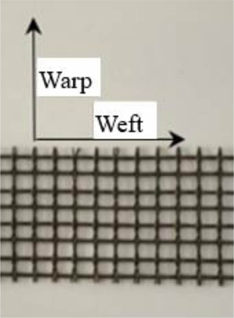
The 210 mm × 110 mm × 48 mm sintered regular bricks had a compressive strength of 8.56 MPa, while the masonry mortar had a compressive strength of 12.7 MPa. The observed mechanical parameters provided by the manufacturers of the basalt textile are displayed in Table 1 and its pore size is 5 mm × 5 mm (Fig. 1). The BTRC matrix has a compressive strength of 41.0 MPa and is a high-performance fine concrete [40], with a mix ratio shown in Table 2. The compositions of the interfacial agents for cement expanded mortar and cement slurry are shown in Table 3, and the cement employed is ordinary Portland cement (OPC) of grade 42.5.
Specimen production
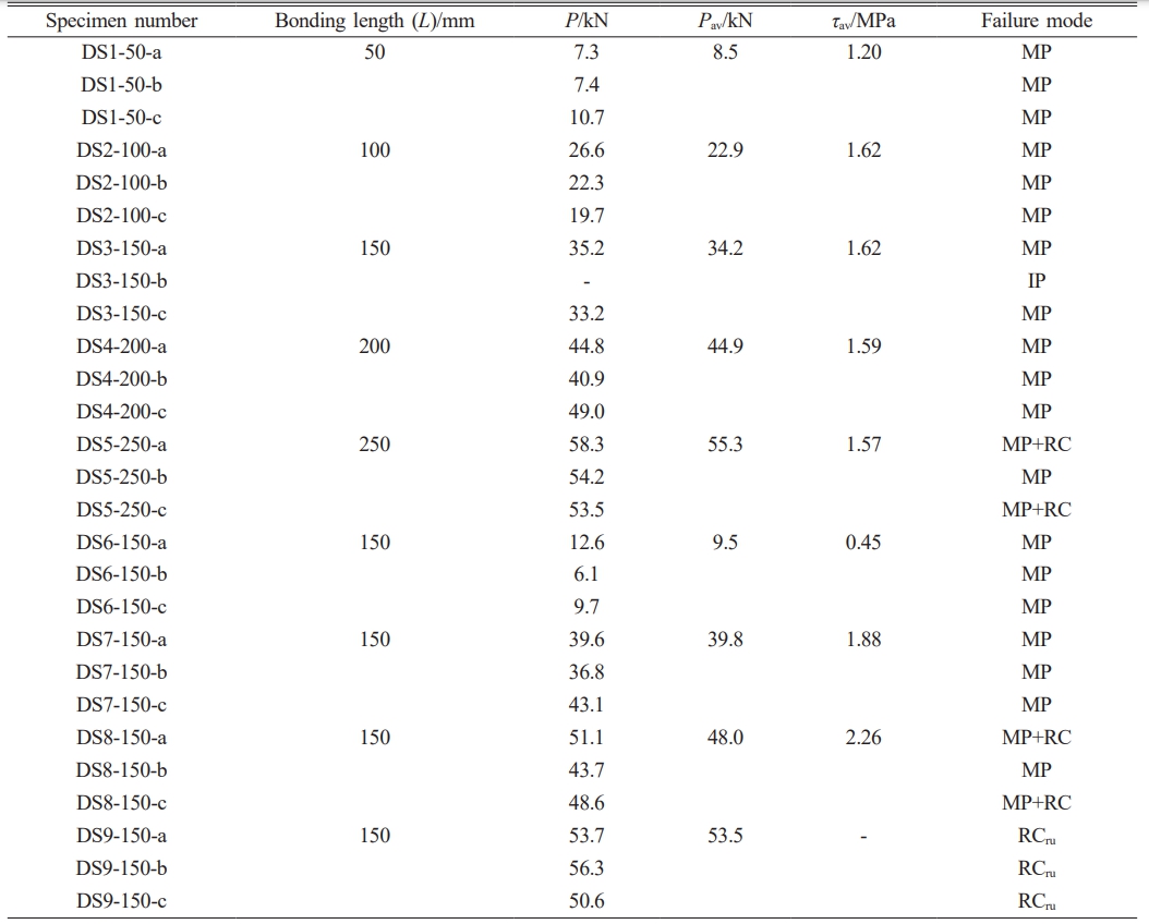
For B-M interface, there were nine groups (DS1-DS9; DS stands for double-sided shear) in the double-sided shear tests, and three specimens in each group meant a total of 27 specimens (Table 4). Process of reinforcement: 1) Dust off the brickwork surface and thoroughly wet it; 2) Position the mold 30 mm from the edge and coat the mold's surface with a 5 mm thick coating of matrix; 3) Press the textile into the matrix and cover it with another layer of matrix. Tests were carried out 28 days following conventional curing. A 5-mm groove was carved into the grey joints of specimens with mortar joint treatment, or a 1-1.2 mm coating of interfacial agents was placed to the surface that needed reinforcement.
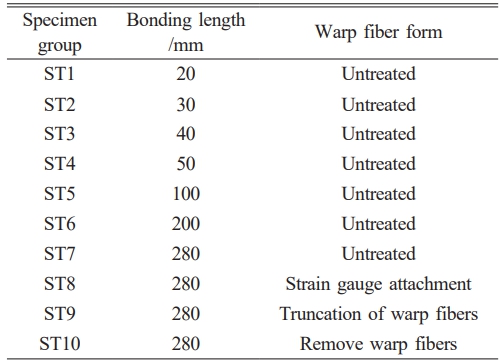
For T-M interface, ten groups (ST1~ST10; ST stands for single-sided tensile) of three specimens each made up the single-sided shear tensile test. A total of thirty specimens with the identical bond width of 70 mm were used [41, 42] (Table 5). The method of manufacture was the same as for the double-sided shear specimens, except that the textile was 300 mm longer than the matrix. The end of the textiles was attached with an aluminum sheet following a 28-day curing period. To make measuring and loading displacement easier, angular aluminum was also fastened to the loading end.
Test setup and measurement point arrangement
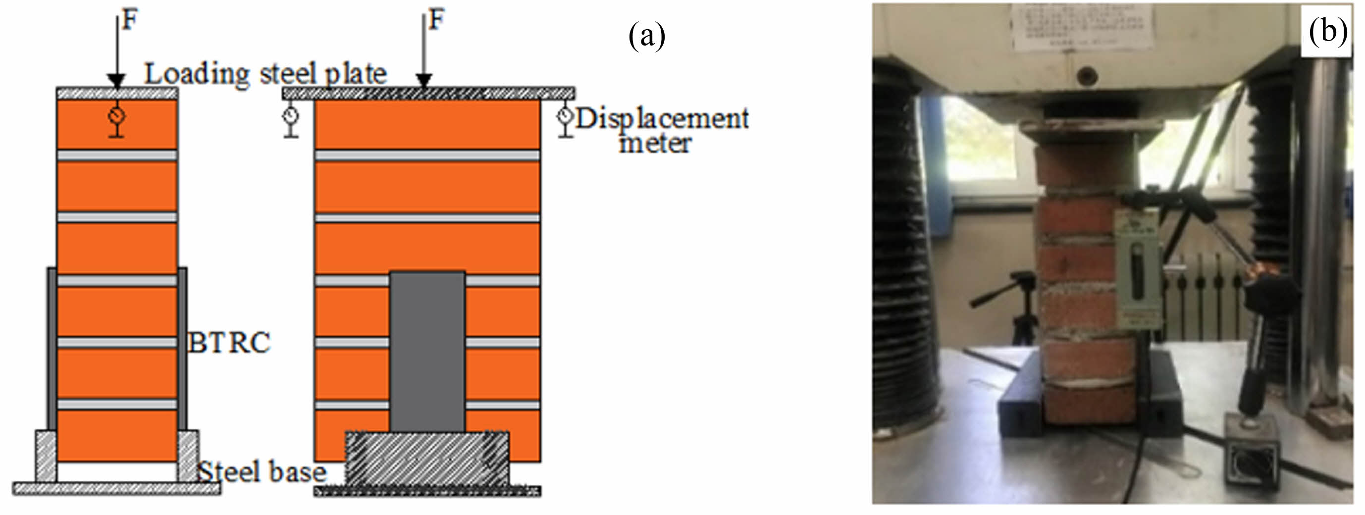
The double-sided shear test setup comprised a steel seat, a loaded steel plate, and a pressure tester with a range of 300 kN (Fig. 2). The loading was displacement-controlled at a rate of 0.5 mm/min [40]. The displacements of the reinforcement layer relative to the masonry prisms were measured using a displacement meter, while the tester's system recorded the loads [41].
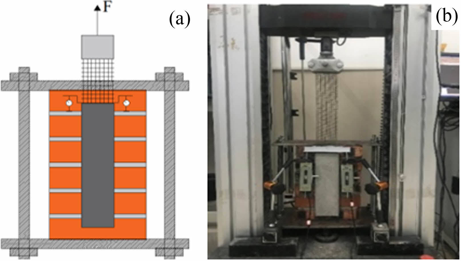
A steel frame and drawing apparatus made up the setup for the single-sided shear tensile test (Fig. 3) [30, 41]. For the single-sided shear test, the maximum load was less than 3 kN, so the testing machine with a range of only 20 kN was used, with displacement-controlled loading occurring at a pace of 0.18 mm/min [30]. A displacement meter is used to measure the displacement at the loading end, and strain gauges are used to measure the strain of the textile. Strain gauges were pasted on the intermediate fiber bundles of the fiber network inside the matrix with a spacing of 15 mm, and a total of 14 strain gauges were arranged from the loaded end to the free end.
Failure process and pattern
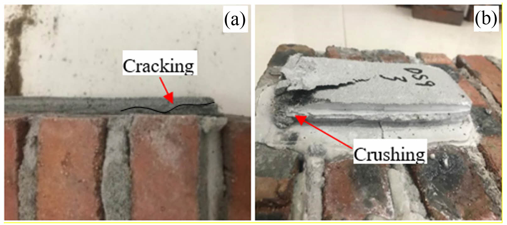
For B-M interface, for the majority of specimens in DS1-DS7, no notable phenomena were seen during the pre-loading phase. When the reinforcing layer reached its maximum load, it suddenly separated from the brickwork surface with a loud bang and brittle damage. The brickwork included the majority of the damaged surfaces (Figs. 4a and 4b). This suggests that the brickwork contained the weak interfacial layer. Furthermore, the uncleaned surfaces that were supposed to be strengthened on individual specimens resulted in poor interfacial bonding and damaged surfaces at the interface (Fig. 4c). Furthermore, because of the uneven stress surface of the reinforcing layer, several specimens showed stress-concentrated cracking at the T-M contact. At the moment of injury, this cracking was less noticeable (Fig. 5a). However, as seen in Fig. 5b, the bottom of the reinforcement layer was crushed and damaged in the DS9 specimen group, despite having a well-bonded interface.
For T-M interface, the single-sided shear tensile test's initial phase produced no noticeable phenomena. But as soon as the ST1 set of specimens reached their maximal load, the reinforcing layer abruptly separated from the masonry's surface (Fig. 6a). The abrupt rupture of the textile, which was followed by a loud fiber fracture sound, fractured the remaining specimens in a brittle way; the internal fiber filament is located at the end of the extracted fiber bundle (Figs. 6b and 6c) [43].
|
Fig. 1 Basalt textile used in the tests. |
|
Fig. 2 Illustration of the double-sided shear test: (a) Schematic diagram and (b) Device diagram. |
|
Fig. 3 Illustration of the single-sided shear tensile test: (a) Schematic diagram and (b) Device diagram. |

|
Fig. 4 Double-sided shear test failure mode of delamination of reinforced layer: (a) Delamination of reinforced layer, (b) Destroy from brick body and (c) Destroy from the interface. |
|
Fig. 5 Double-sided shear test failure mode of reinforcement destruction: (a) Cracking of reinforced layer and (b) Crushing of reinforced layer. |

|
Fig. 6 Single-sided shear tensile failure mode: (a) Stripping of reinforcement layer, (b) The fiber was pulled out from the matrix and (c) The fiber broke at the root. |
|
Table 5 Design parameters of the specimens for single-sided shear tensile tests. |
Analysis of shear strength at the interface B-M
The Eq. (1) is utilized to compute the interfacial shear strength of B-M, where τ and τav represent the shear strength and its average value, MPa; P and Pav represent the maximum interfacial bond force and its average value, N; and A denotes the interfacial area, mm². The value of A is calculated as A = 2A0, where A0 is the unilateral interfacial area, mm². Table 6 displays the calculation results; MP denotes the peeling of the reinforcement with the damaged surface within the masonry; IP is the peeling at the interface; RC is the cracking of the reinforcement; and RCru means the reinforcement crushing. The analysis excluded the DS3-b due to the improper fabrication. Furthermore, the formula cannot be used to calculate the DS9 group of specimens as the reinforcement layer has not been peeled off.

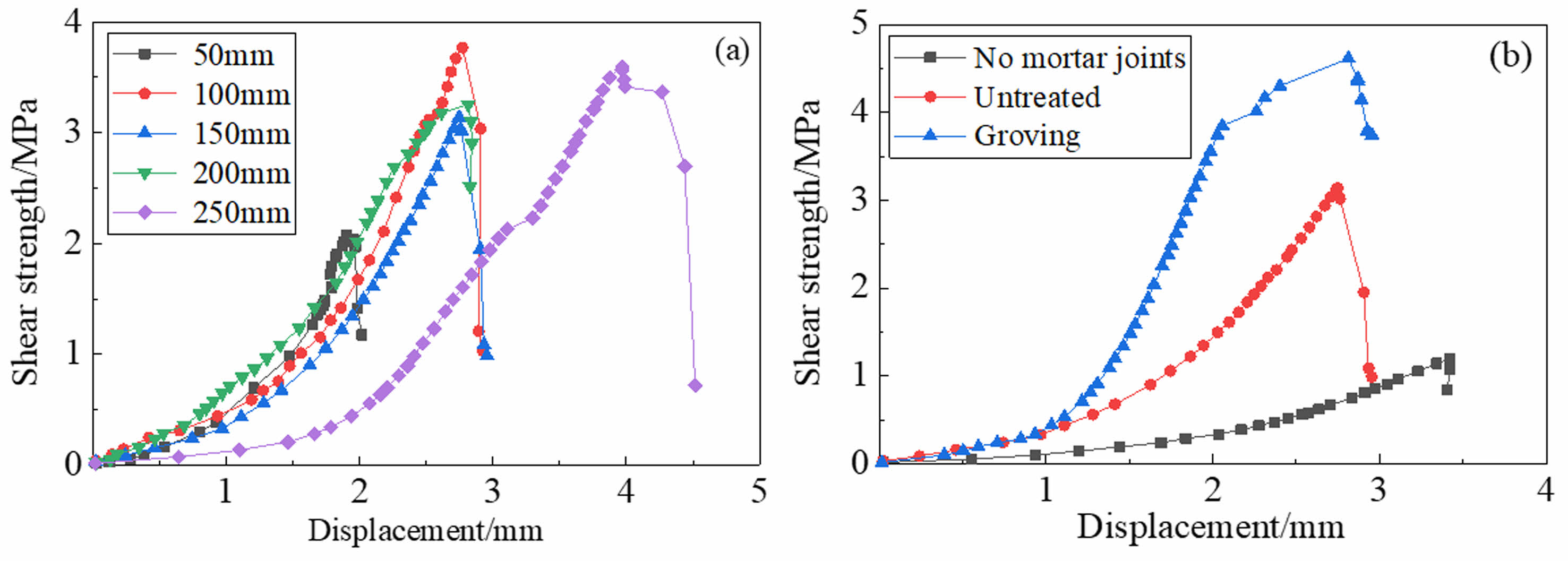
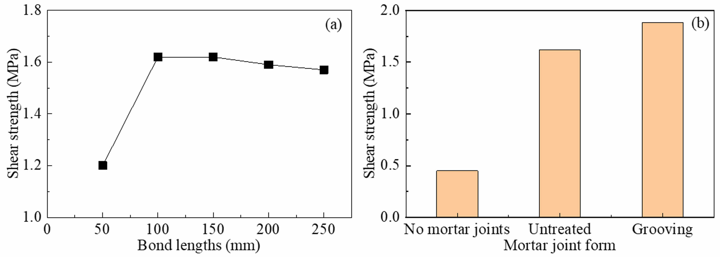
Fig. 7a shows the shear strength-displacement curves of the specimens. It is clear from Table 6 that, with the exception of the DS1 group, the shear strengths of the DS2-DS5 specimen groups are virtually identical. This implies that bond lengths have a negligible impact on shear strengths (Fig. 8a). The shear strength of the masonry depends mainly on the brick strength due to the consistent damage mechanism of the interface, therefore, the strength remains consistent. The interface bond of the 50 mm bonding length specimen is mostly dependent on the mortar joints of the bonding region, as they constitute a bigger area. The strength of the bricks is significantly lower than that of the mortar joints. Cracks in the mortar joints quickly spread through the bricks at the contact, leading to reduced shear strength.
The shear strengths of untreated mortar joints DS3 and treated mortar joints DS7 increased by 260% and 318.9% when compared to DS6 (Table 6, Fig. 7b and Fig. 8b). The mortar joints are effective in improving interfacial shear strength. The mortar joints enhance the roughness of the interface and promote the mechanical connection between the reinforcement and the masonry surface. The grooving treatment further improves the interface roughness.
The shear strength of DS7, DS8, and DS9 specimens rose by 16%, 40.4%, and 56.4% compared to the DS3 specimen, as shown in Table 6. Using a flat-applied interfacial agent is more effective than grooving treatment of mortar joints for enhancing shear strength. Moreover, the utilization of cement-expanded slurry interfacial agent was discovered to be more efficient. Cement mortar enhances adhesion to brick surface by creating a significant amount of needle-like calcium aluminate during the hydration reaction, which infiltrates into the pores of the brick surface and forms a strong connection with it. Utilizing an expansion agent decreases drying fractures and results in a denser structure at the interface, ultimately improving the strength of the interfacial transition zone [44].
Bond strength analysis of T-M interface
The interfacial bond strength is characterized using the bond strength formula in [45, 46] as most of the damage was caused by the fiber bundles pulling apart without significant slip:

where σ represents the bond strength at the T-M interface; σav is the corresponding average value, MPa; Pmax is the maximum load of the textile in the fracture damage mode, N; n is the number of fiber bundles contained in the bonded region; and Ab is the area of fiber bundle under stress, mm2.
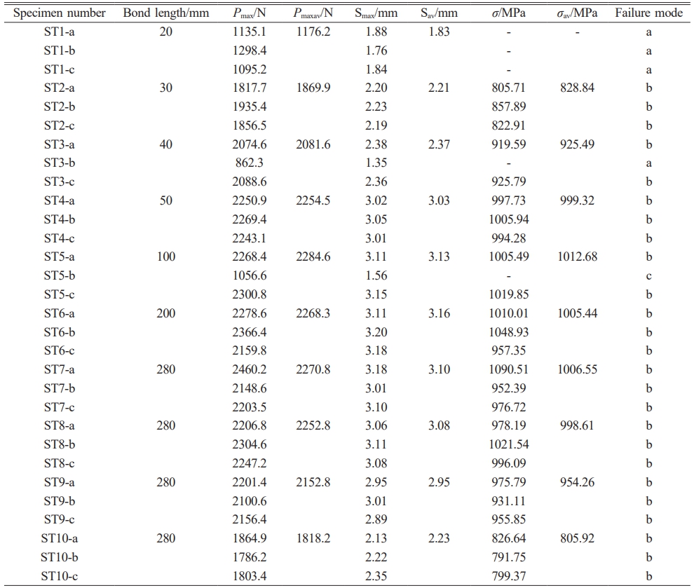
The calculation results are summarized in Table 7, where a, b and c correspond to the three damage forms of Figs. 6a, 6b, and 6c; Pmaxav is the average value of peak loads, N; Smax means the peak displacement at the loaded end, mm; and Sav is the corresponding average value, mm. The ST1 group and ST3-b experienced interfacial stripping damage, while the external textile of the ST5-b matrix was also damaged. The relevant data were discarded.
Fig. 9a illustrates the load-displacement curves of specimens with varying bond lengths, showing the relationship between bond length and strength. Bond strength rises as bond length increases, reaching stability when the bond length is ≥ 50 mm. The textile was securely fixed to the matrix, and only the inner fibers were removed at the loading end when damaged. Internal fibers were restricted by fibers in the free end after debonding from the outer fiber. Once the bond length beyond a specific threshold, the distal fibers in the free end lost their ability to restrict the loaded fibers, resulting in no further rise in bond strength (Fig. 10a). Fig. 9b and Fig. 10b show the load-displacement curves and bond strength of the specimens with different forms of warp fibers. Removing and cutting warp fibers decreased peak loads by 4.4% and 19.3%. The shearing of the warp fibers affected the synergy with the weft fiber bundles, but the sheared fibers remained imbedded in the matrix to restrict the weft fibers. The fiber laps also contributed to mechanical occlusion, leading to a little shift in the damage load. Removing the warp fibers led to a total lack of restrictions and a notable reduction in the damage load.
Bonding mechanism research
The bond at the B-M contact often involves chemical bonding, Van der Waals forces, and mechanical occlusion, comparable to the link between old and new concrete [47]. The chemical bond forms crystals at the contact through the hydration process to connect the reinforcing layer to the brickwork. As the interfacial shear force rises, the crystals are sheared off because of relative slip at the interface, leading to the rupture of the chemical bond. The Van der Waals force results from the contact between molecules in a crystal. The brick body surface is porous, causing increased molecular spacing and reduced intermolecular forces. The mechanical occlusion force arises from the irregularities on the bonded surface, mostly affected by the roughness of the contact. The mechanical occlusion force is mainly produced by the hydration products of the TRC matrix entering the pores of the brickwork and causing the reinforcement layer to blend with the masonry at a microscopic level.
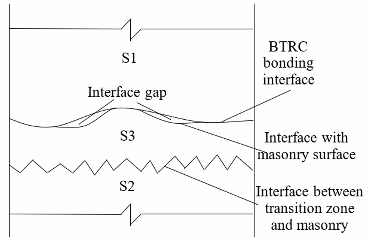
The test findings showed that the specimens experienced mostly reinforcement peeling, and the damage surface was in the brickwork. Damage was present not only at the B-M contact but also in a less severe transition zone at the BTRC-masonry interface. The compressive strength of the brick is 20.9% of the compressive strength of the matrix. The damaged surface was not located within the matrix, unlike the interfacial link between new and old concrete. A dual-interface-multilayer zone transition bonding model was presented, which includes the BTRC zone S1, the masonry zone S2, and the masonry bond transition zone S3 (Fig. 11).
The bonding transition zone includes the BTRC bond interface, the masonry surface contact, the gaps between them, and the section of the brickwork. The BTRC matrix seeped into the pores of the stonework, forming a fragile bond area that broke when it reached its maximum stress. Spaces between the two-sided interfaces in vulnerable areas may lead to the bonded area becoming porous and weak, hence diminishing the bonding effectiveness of the B-M interface. These gaps can result from a variety of factors: a) Impurities like dust, air bubbles, grease, and debris were present on the masonry surface during reinforcement; b) Inadequate application of concrete matrix during consolidation; c) The contact geometry effect of interfacial bonding caused only the edges of cement particles in the matrix to touch the masonry, leaving the space between interfaces unfilled with cement hydrate; d) Pores on the masonry surface were not filled with cement particles. Thus, improving the spacing between the double interfaces and increasing the density of the bonding transition zone can boost bonding performance. Apply a coating of cementitious mortar of the same kind as the matrix concrete to the surface of the masonry before applying reinforcement. To enhance the structural density of the reinforced region while reducing the infiltration of cement paste from the matrix into any voids. The avoidance of pore development in the bonded area occurs because the cement paste is not diminished, leading to enhanced interfacial bonding capabilities. The findings in section 2.1 confirm the idea. The inclusion of the expansion agent led to a more compact interfacial structure, enhancing the interfacial bonding performance.
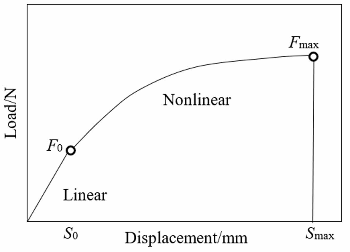
The bond force for the T-M interface comprises mainly the chemical adhesion between the fine aggregate concrete matrix and the textile, the frictional resistance of the surrounding fine aggregate concrete matrix to the textile, and the mechanical occlusion force formed between the surface of the textile and the fine aggregate concrete matrix [48]. By examining the experimental phenomena and load-displacement curves at the loading end (Fig. 12), the process of separating textile from the matrix can be categorized into linear and nonlinear phases. Linear phase: The bond at the interface remained unbroken initially under the load; both the interface and the textile were in the elastic deformation stage, and the load was directly proportional to the slip. Non-linear phase: The inner fiber filaments at the load end broke when the load hit F0. At the maximum force Fmax, several fiber filaments fractured, resulting in the breakage and extraction of the fiber bundle. The inner fiber filaments were only extracted because of the strong bonding at the T-M contact at the load end.
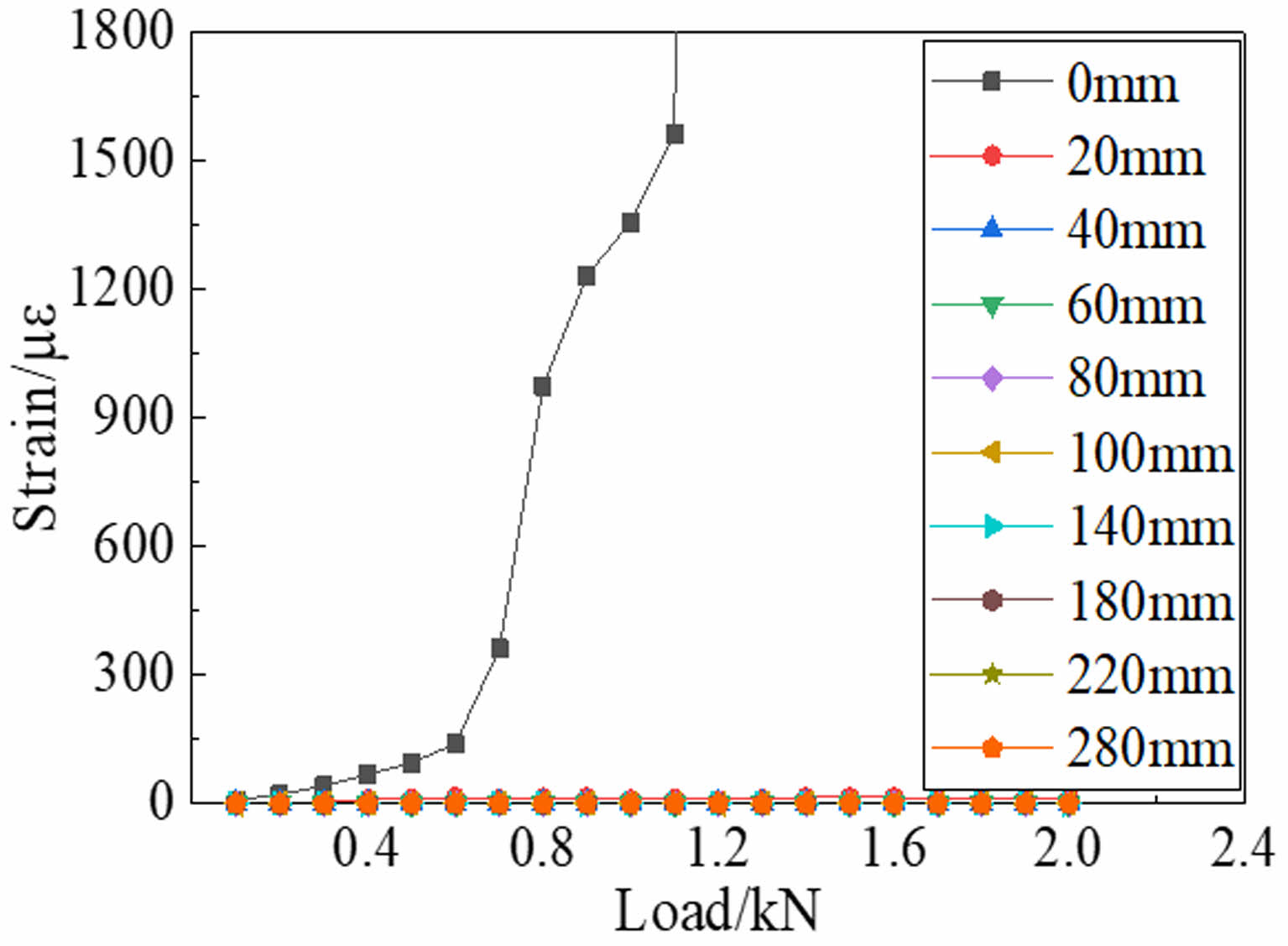
The T-M interfacial interactions in both phases have a direct impact on the strengthening, toughening, and crack-resistant properties of BTRC on masonry. Bond strength at the beginning of the test was mainly influenced by the chemical adhesive force during fiber elastic deformation. As the load rose, the internal fiber filaments in the fiber bundle toward the loading end started to break. When the tension at the interface equaled the tensile strength of the textile, the fibers fractured and were extracted from the matrix. Only the interior fiber filaments were extracted as the exterior fibers exhibited superior adhesion to the matrix and were more strongly attached than the fiber filaments. The textile strain was seen at the loading end, but the friction-dominated dynamic slip phase was not observed (Fig. 13), in contrast to reinforced concrete bonding [29, 49].
Brittle damage occurred when the tension on the interface approached the tensile strength of the textile, causing internal fibers to break and release energy due to a strong link at the interface. In masonry reinforcing projects, only a section of the textile breaks in case of damage to the structure or part; And the intact fabric retains its structure and precludes total collapse.
The literature [35] examined the bond-slip connection between the textile and the matrix by utilizing the ontological relationship of the fiber bundle and making various assumptions. Any little segment dx was intercepted in the direction of the force acting on the fiber bundle. Based on the interfacial equilibrium relationship, the connection between interfacial stress and displacement may be determined as follows:

where u represents the fiber bundle displacement; τx represents the local bond shear stress in the dx section; and Px, E, and Ax represent the fiber bundle perimeter, elastic modulus, and cross-sectional area. The local slip may be calculated by integrating the strain of the fiber bundle starting at the free end. Integrating the local displacement function ux with Eq. (3) yields the local bond shear stress-slip relationship (τx-u).
To obtain the strain function, the researchers affixed strain gauges to the surface of the reinforcement layer. The surface strain of the reinforcement layer was considered as the interface strain between the textile and the matrix [50]. And digital correlation techniques (DIC) have been used to investigate stress-strain conditions on the matrix surface [51, 52]. Both methods are inadequate for accurately representing the interfacial strain. The most direct approach is to place strain gauges in the reinforcement matrix after attaching them on the surface of the fiber bundles [49]. Alternatively, a textile containing strain gauges can be attached following the flat application of the bottom reinforcement layer, without including the upper reinforcement layer [53]. This approach enables the direct monitoring of the surface strain of the fiber bundles. The strain gauges were attached directly to the surface of the fiber bundle. Strain gages may detach because of friction when force is transferred via fiber bundles and the matrix, as they are attached to the fiber bundles and embedded in the matrix. Arranging the strain gages too closely together is challenging when trying to accommodate the strain function. During the test, only the strain at the loaded end changed and no slip phenomena occurred, which made it impossible to match the strain function.
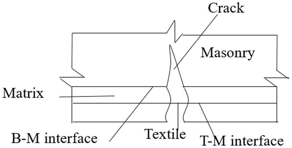
In practical engineering, the reinforcing layer constrains the masonry by bonding with the B-M interface as it deforms under stress. This constrains its deformation and postpones the creation of fissures. Once the external force above a specific threshold, cracks form in both the brickwork and the reinforcing layer matrix. The uncracked masonry surface is now restricted by the reinforcing layer due to the bonding at the B-M contact. The textile largely limits the brickwork distortion at the fissures. The T-M interfacial bond is in a dominant restraining position until the load above a certain threshold, leading to textile breakage and the reinforcement losing its restraining action (Fig. 14). The article notes that the two interfaces of BTRC-reinforced masonry are strongly bound. The damage surface of the B-M interaction is situated inside the masonry body. If the bond length is adequate to avoid peeling of the B-M interface, the textile will effectively fulfill its intended purpose.
Minimum bond length
To achieve the reinforcement effect, the minimum bond length Lmin is proposed, and when the bond length ≥ Lmin, the two interfaces are not damaged before the textile is taken off and the peak load dose not increase. Single-sided shear tensile tests indicated that when the bond length was small (≤ 20 mm), the B-M interface had been degraded before reaching the debonding length. No debonding damage of the fiber bundles from the matrix was seen in any of the experiments as a result of the textile can operate effectively as long as the bonding length guarantees a strong connection at the B-M contact. This corresponds to the shortest bonding length, Lmin. Simply put, the critical condition occurs when the bonding force at the B-M contact meets the maximum fracture force of the textile.

where nt is the number of textile layers; m is the number of fiber bundles per unit width (1 m); and F is the single-bundle fiber breaking strength, 308 N. It is advised to use m times the breaking load of a single fiber bundle as the breaking force of the textile to maintain a cautious approach. Usually, this number is less than the combined breaking loads of the separate fiber bundles.
Calculation of shear strength at the B-M interface
The analysis of the shear strength of the B-M interface, a crucial element in establishing the minimum bond length, is the primary focus of the investigation. The interface shear strength is mainly influenced by the axial tensile strength of the bricks, which is correlated with the strength class of the bricks [54]. The suggested method for determining the average shear strength of the B-M interface takes into account the similarities between the features of pure shear damage at the B-M interface and masonry damage along the toothed joint section.

where τp indicates the calculated value of the shear strength at the B-M interface, MPa; fc and α indicate the compressive strength of the bricks, MPa, and the impact factor of the compressive strength. Four sets of test data were chosen and calculated to determine the impact factor. Their average values (αav) were taken as α (Table 8). Substituting α = 0.52 into Eq. (6) gives τp = 1.51, and the relative error is 3.8% compared to the DS5 data, indicating that the formula can better estimate the average value of the shear strength at the B-M interface.
Calculation of minimum bond length
To get the minimum bond length, substitute the B-M interface shear strength calculation formula into Eq. (5).

The test results indicated that the minimum bond length ranged from 40 mm to 50 mm, with a conservative value of 50 mm. The predicted value of 40.79 mm was underestimated due to the omission of the matrix restriction on the fiber bundle. For the purpose of engineering safety, a proposed minimum bond length amplification factor k (k >1) is used. The value is found by dividing the test value by the estimated value, where k = 1.23, so:
|
Fig. 7 B-M interface shear strength-displacement curves under (a) Different bond lengths and (b) Different mortar joint depth |
|
Fig. 8 B-M interface shear strength under (a) Different bond lengths and (b) Different mortar joint depth. |

|
Fig. 9 Load-displacement curves under (a) different bond lengths and (b) different warp fibers treated ways in single-sided tensile testing for T-M interface. |

|
Fig. 10 Bond strength under (a) different bond lengths and (b) different warp fibers treated ways in single-sided tensile testing for T-M interface. |
|
Fig. 11 Illustration of the dual-interface-multilayer zone transition bonding for B-M interface. |
|
Fig. 12 Schematic diagram showing the relationship between loading end force and displacement. |
|
Fig. 13 Illustration of textile strain changes at different positions in single-sided tensile testing |
|
Fig. 14 Schematic diagram showing the bonding interface work of BTRC reinforced brick masonry. |
|
Table 7 Experimental results of single-sided shear tensile tests on T-M interface. |
|
Table 8 Calculation of influence coefficient of compressive strength of fired common brick. |

The bonding performance of BTRC reinforced masonry interface was studied through double-sided shear and single-sided shear tensile tests. The test results were used to analyze the bonding mechanism. The following are the main conclusions:
(1) In the shear damage mode, the shear strength of the bond-matrix interface first rose with bond length, steadied, and then became less dependent on bond length. Increased interfacial mechanical occlusion from mortar joints greatly enhanced the interfacial bonding characteristics, and these qualities might be further improved by mortar joints with grooves. Interfacial bonding performance is efficiently improved by the use of an interfacial agent because the inclusion of the agent changed the damage mode and increased the shear strength of the cement expanded mortar specimen by 55.9% and the cement net mortar specimen by 39.2%.
(2) The bond strength for the T-M interface increases and then stabilizes with the bond length. When the bond length was less than or equal to 20 mm, the BTRC peeled off from the masonry, and the peak load no longer increased beyond 50 mm. The peak loads decreased by 4.4% and 19.3% after cutting and removal of the meridional fibers. This suggests that the meridional fibers played a role in enhancing the interfacial bond strength, and the special shape of the warp and weft junction and the embedding of the warp fibers in the matrix enhance the constraint of the matrix on the weft fibers.
(3) Based on the test findings, the BTRC-masonry double-interface-multi-layer transitional bond model is proposed. The bond between the T-M interfaces ensures minimal relative slip at the interfaces during stress transfer along the stressed fiber bundle, and the drawing process is divided into a linear stage and a nonlinear stage. The minimum bond length and corresponding calculation formula were suggested based on experiments and mechanism studies, also the calculation method of B-M interface shear strength was studied.
- 1. Z. Yang, F. Xiong, M. J. Yu, and Q. Ge, China Civil Eng. J 51[S2] (2018) 41-47.
- 2. T.-H. Ahn, J. Ceram. Process. Res 17[1] (2016) 59-66.
-

- 3. L.A.S. Kouris and T.C. Triantafillou, Constr. Build. Mater. 188 (2018) 1221-1233.
-

- 4. M.R. Valluzzi, C. Modena, and G. De Felice, Mater Struct. 47[12] (2014) 1971-1985.
-

- 5. P.E. Mezrea, I.A. Yilmaz, M. Ispir, E. Binbir, I.E. Bal, and A. Ilki, J. Compos. Constr. 21[3] (2017) 04016110.
-

- 6. M. Fossetti and G. Minafo, Composites, Part B 112 (2017) 112-124.
-

- 7. F.A. Kariou, S.P. Triantafyllou, D.A. Bournas, and L.N. Koutas, Constr. Build. Mater. 165 (2018) 769-781.
-

- 8. G. Marcari, M. Basili, and F. Vestroni, Composites, Part B 108 (2017) 131-142.
-

- 9. L. Jing, S.P. Yin, F. Aslani, and S. Liu, Adv. Struct Eng. 24[13] (2021) 3057-3069.
-

- 10. F.G. Carozzi, A. Bellini, T. D'Antino, G. de Felice, F. Focacci, Ł. Hojdys, L. Laghi, E. Lanoye, F. Micelli, M. Panizza, and C. Poggi, Composites, Part B 128 (2017) 100-119.
-

- 11. M. Leone, M.A. Aiello, A. Balsamo, F.G. Carozzi, F. Ceroni, M. Corradi, M. Gams, E. Garbin, N. Gattesco, P. Krajewski, C. Mazzotti, D. Oliveira, C. Papanicolaou, G. Ranocchiai, F. Roscini, and D. Saenger, Composites, Part B 127 (2017) 196-214.
-

- 12. G.P. Lignola, C. Caggegi, F. Ceroni, S. De Santis, P. Krajewski, P.B. Lourenço, M. Morganti, C. Papanicolaou, C. Pellegrino, A. Prota, and L. Zuccarino, Composites, Part B 128 (2017) 1-18.
-

- 13. C. Caggegi, F.G. Carozzi, S. De Santis, F. Fabbrocino, F. Focacci, Ł. Hojdys, E. Lanoye, and L. Zuccarino, Composites, Part B 127 (2017) 175-195.
-

- 14. S. De Santis, F. Ceroni, G. de Felice, M. Fagone, B. Ghiassi, A. Kwiecień, G.P. Lignola, M. Morganti, M. Santandrea, M.R. Valluzzi, and A. Viskovic, Round robin test on tensile and bond behavior of steel reinforced grout systems. Composites, Part B 127 (2017) 100-120.
-

- 15. G. De Felice, T. D'Antino, S. De Santis, P. Meriggi, and F. Roscini, Front Built Environ. 6 (2020) 1-15.
-

- 16. V. Alecci, M. De Stefano, R. Luciano, L. Rovero, and G. Stipo, J. Compos. Constr. 20[1] (2015) 04015041.
-

- 17. L. Ombres, N. Mancuso, S. Mazzuca, and S. Verre, J. Mater. Civ. Eng. 31[1] (2019) 04018356.
-

- 18. F.G. Carozzi and C. Poggi, Composites, Part B 70 (2015) 215-230.
-

- 19. N. Gattesco and I. Boem, Compos. Struct. 165 (2017) 209-222.
-

- 20. P.D. Askouni and C.G. Papanicolaou, Mater Struct. 50[2] (2017) 164.
-

- 21. P.D. Askouni and C.G. Papanicolaou, Constr. Build. Mater. 207 (2019) 535-547.
-

- 22. A. Bilotta, F. Ceroni, and E. Nigro, Constr. Build. Mater. 138 (2017) 114-133.
-

- 23. P.D. Askouni and C.G. Papanicolaou, RILEM Book Series 15 (2018) 527-534.
-

- 24. C. Carloni, S. Verre, L.H. Sneed, and L. Ombres. Composites, Part B 108 (2017) 301-304.
-

- 25. A. Bellini, S.K. Shahreza and C. Mazzotti, Composites, Part B 169 (2019) 189-199.
-

- 26. M. Saidi, N. Reboul, and A. Gabor, Composites, Part B 247 (2022) 1-17.
-

- 27. A. Bilotta, F. Ceroni, G.P. Lignola, and A. Prota, Composites, Part B 129 (2017) 251-270.
-

- 28. M. Tekieli, S. De Santis, G. de Felice, A. Kwiecień, and F. Roscini, Compos. Struct. 160 (2016) 670-688.
-

- 29. F.G. Carozzi, P. Colombi, G. Fava, and C. Poggi, Compos. Struct. 143 (2016) 230-241.
-

- 30. L. Ascione, G. de Felice, and S. De Santis, Composites, Part B 78 (2015) 497-506.
-

- 31. L. Ascione, F.G. Carozzi, T. D’Antino, and C. Poggi, Procedia Struct. Integr. 11 (2018) 202-209.
-

- 32. S. De Santis, H.A. Hadad, F. De Caso Basalo, G. De Felice, and A. Nanni, J. Compos. Constr. 22[6] (2018) 04018408.
-

- 33. F. Ceroni and P. Salzano, Composites, Part B 143 (2018) 230-242.
-

- 34. E. Franzoni, C. Gentilini, M. Santandrea, S. Zanotto, and C. Carloni, Mater. Struct. 50[4] (2017) 1-16.
-

- 35. E. Franzoni, C. Gentilini, M. Santandrea, and C. Carloni, Constr. Build. Mater. 175 (2018) 225-238.
-

- 36. E. Franzoni, M. Santandrea, C. Gentilini, A. Fregni, and C. Carloni, Constr. Build. Mater. 209 (2019) 592-605.
-

- 37. L. Ombres, A. Iorfida, S. Mazzuca, and S. Verre, Meas. 125 (2018) 509-515.
-

- 38. M. Malena and G. De Felice, Compos. Struct. 112[2] (2014) 194-206.
-

- 39. M. Malena, Composites, Part B 139 (2018) 249-258.
-

- 40. S.P. Yin, L. Zhao, D.F. Qiang, and P.H. Li, Mater. Rep. 31[A1] (2017) 346-350.
- 41. T. D’Antino, C. Carloni, L.H. Sneed, and C. Pellegrino, Eng. Fract. Mech. 117 (2014) 94-111.
-

- 42. C. Carloni, T. D'Antino, L.H. Sneed, and C. Pellegrino, J. Eng. Mech. 141[6] (2015) 04014165.
-

- 43. ACI 549.6R-2020, ACI (2020).
- 44. P. Fang, Z.Y. Huang, S.P. Shang, and R.P. Zhang, J. Build. Struct. 31[3] (2010) 45-50.
- 45. C. Carloni, T. D’Antino, L.H. Sneed, and C. Pellegrino, J. Compos. Constr. 22[1] (2018) 04017048.
-

- 46. P. Colombi and T. D'Antino, Compos. Struct. 220 (2019) 961-970.
-

- 47. H.C. Xie, G.Y. Li, and G.J. Xiong, Bull. Chin. Ceram. Soc. 22[3] (2003) 5.
- 48. L.B. Greszczuk, Interfaces Compos. (1969) 42-58.
-

- 49. A. D'Ambrisi, L. Feo, and F. Focacci, Composites, Part B 43[8] (2012) 2938-2949.
-

- 50. C. Sabau, J.H. Gonzalez-Libreros, L.H. Sneed, G. Sas, C. Pellegrino, and B. Taljsten, Mater. Struct. 50[3] (2017) 172.
-

- 51. T. D'Antino, L.H. Sneed, C. Carloni, and C. Pellegrino, Compos. Struct. 142 (2016) 117-129.
-

- 52. C. Caggegi, D. Sciuto, and M. Cuomo, Meas. 129 (2018) 119-127.
-

- 53. L.H. Sneed, T. D'Antino, and C. Carloni, ACI Mater. J. 111[5] (2014) 569-580.
-

- 54. T. Linse, N. Gebbeken, T. Araújo, and R.M. Silva, Blucher Mech. Eng. Proc. 1[1] (2012) 909-931.
-

 This Article
-
2024; 25(6): 985-996
Published on Dec 31, 2024
- 10.36410/jcpr.2024.25.6.985
- Received on Aug 5, 2024
- Revised on Sep 12, 2024
- Accepted on Oct 14, 2024
 Services
- Abstract
introduction
experimental program
discussion of experimental results
conclusions
- References
- Full Text PDF
Shared
 Correspondence to
- Peijian Yang
-
School of Civil and Transportation Engineering, Hebei University of Technology, Tianjin 300401, China
- E-mail: 13132276339@163.com


 Copyright 2019 International Orgranization for Ceramic Processing. All rights reserved.