- Initiation of secondary surface crack in the ring raceway of silicon nitride full ceramic bearing
Pengfei Wanga,b, Songhua Lia,c,*, Yuhou Wua,c and Jining Zhaoa
aSchool of Mechanical Engineering, Shenyang Jianzhu University, Shenyang 110168, China
bSchool of Intelligent Manufacturing, Panzhihua University, Panzhihua 617000, China
cNational-Local Joint Engineering Laboratory of NC Machining Equipment and Technology of High-Grade Stone, Shenyang Jianzhu University, Shenyang 110168, Liaoning, ChinaThis article is an open access article distributed under the terms of the Creative Commons Attribution Non-Commercial License (http://creativecommons.org/licenses/by-nc/4.0) which permits unrestricted non-commercial use, distribution, and reproduction in any medium, provided the original work is properly cited.
The existing application feedback and RCF study of silicon nitride ceramic bearings show that the main failure mode of silicon nitride full ceramic bearings is the material spalling on the rolling contact surface. The spalling failure is caused by the expansion of the main surface crack and the initiation and expansion of the secondary surface crack under the rolling contact. Therefore, in the current widespread application of silicon nitride full ceramic bearings, in order to improve the spalling fatigue life of silicon nitride ceramic bearings, we can only start from the perspective of studying the main surface crack propagation and secondary surface crack initiation and expansion mechanism of silicon nitride ceramic bearings. In this paper, on the one hand, the Franc3D and ABAQUS joint simulation calculation of the rolling contact tensile stress of different surface main crack parameters (initial depth and initial inclination angle) and different rolling contact friction coefficients leading to secondary surface crack initiation was completed. On the other hand, based on the fracture toughness experiment of silicon nitride material, the critical initial size of the secondary surface crack generated near the main surface crack is calculated, and many useful conclusions are obtained. The research results will be able to improve the service life of silicon nitride ceramic ball bearings by guiding the development of grinding technology of silicon nitride ceramic ball bearings and the regulation of service parameters of silicon nitride ceramic ball bearings.
Keywords: Silicon nitride full ceramic bearing, Spalling fatigue failure, Fracture toughness test experiment, Joint simulation, Secondary surface crack initiation.
With the progress of science and technology and the development of industrial production, silicon nitride ceramic bearings have been widely used because of their advantages such as low density, high stiffness, good corrosion resistance [1] and high and low temperature resistance [2-4]. Compared with steel bearings, silicon nitride ceramic bearings not only show advantages in terms of speed [5] and service life [6-9], but also can be used in some special conditions. Such as extreme temperature and high corrosive conditions. However, due to the special hot isostatic pressing sintering and grinding manufacturing process, there are a large number of defects and cracks on the surface and inside of the ring raceway of ceramic bearings. Coupled with the high brittleness [10, 11] of silicon nitride ceramics, the original surface main cracks are easy to expand and cause the initiation of secondary surface cracks nearby under the action of cyclic rolling contact during the service process of silicon nitride ceramics. Then, under the continuous action of cyclic rolling contact, the original surface main crack and the initiation of secondary surface crack will continue to expand and converge, resulting in the final contact surface material spalling failure [12-16]. In recent years, although a lot of research work has been done on the spalling failure of silicon nitride ceramic ball bearings, the failure mechanism of the surface spalling of silicon nitride ceramic ball bearings has not been well understood. Therefore, it is necessary to further study the spalling mechanism of silicon nitride ceramic ring raceway, so as to regulate the processing technology and working parameters to extend the spalling fatigue life of silicon nitride ceramic ball bearings.
In recent years, most researches on the spalling mechanism of silicon nitride have focused on RCF (rolling contact fatigue) experiment and finite element simulation. In terms of RCF experiment, Zhao et al. [17] used an improved four-ball experimental machine to study the effects of three different types of lubricants, including grease, transmission oil and traction oil, on the rolling contact fatigue life of silicon nitride. It is concluded that the use of grease can prevent oil from penetrating into cracks, and can lead to higher friction on crack surface than transmission oil and traction oil, thus increasing the crack propagation resistance of shear propagation mode and the rolling contact fatigue failure time. Karaszewski [18] used a four-ball experimental device to study the effects of four oil additives, chlorine (Cl), sulfur (S), phosphorus (P) and cerium dioxide (CeO2), on the crack growth of silicon nitride. Previous studies [19] have shown that the chemo-mechanical reaction between CeO2 powder and silicon nitride can play a good role in polishing silicon nitride. Therefore, Karaszewski's experimental study results show that among the four additives, CeO2 powder has the best lubrication effect, while S and P have a positive effect on prolonging the failure time of rolling contact fatigue. In order to study and discuss the rolling contact spalling fatigue performance of silicon nitride ceramics with different material physical properties and microstructure, Katz [20] used a four-ball test device to study the rolling contact fatigue performance of NC-132 hot-pressed silicon nitride ceramics in 1987. The results show that the rolling contact fatigue performance of NC-132 silicon nitride is relatively discrete, but its main failure mode is a relatively benign spalling failure mode, rather than a catastrophic fracture like alumina ceramics. In the late 1980s, Zaretzky [21] sorted out the rolling contact fatigue data of ceramics used in bearings of aviation gas turbine engines from the 1960s to the mid-1970s, and proposed the analysis results of life prediction based on these data. He then compared the rolling contact fatigue properties of hot-pressed silicon nitride with those of other ceramic materials such as crystalline glass ceramics, titanium carbide ceramics, alumina ceramics and traditional bearing steels through NASA's five-ball test facility, and found that the rolling contact fatigue life of hot-pressed silicon nitride ceramics is longer than that of other materials. In terms of finite element simulation, at the beginning of the 21st century, Wang's research group used the boundary element method to conduct a large number of finite element calculation studies [22-30], all of which used the calculated characteristics of the stress intensity of the crack front to characterize the influence of their respective research objects on crack propagation. And these numerical analysis results were verified by rolling contact fatigue experiment in subsequent research work.
To sum up, the research direction of the existing research on the spalling mechanism of silicon nitride full ceramic bearings is basically focused on the crack propagation mechanism, and few studies have been carried out on the secondary surface initiation mechanism and its joint propagation with the surface main crack. However, it is obvious that the latter is the key to reveal the spalling fatigue failure mechanism of silicon nitride full ceramic bearings. In this paper, three-dimensional finite element rolling contact models of silicon nitride ceramic inner ring and silicon nitride ceramic ball with surface main cracks in raceway were established, and the joint simulation of ABAQUS and Franc3D was carried out. The rolling contact tensile stress of inner ring raceway with different initial inclination surface main crack, inner ring raceway with different initial depth surface main crack and different rolling contact friction coefficient were calculated for different rolling load contact distance, and the regularity of the calculation results was analyzed. Then, the critical initial size of rolling contact initiation crack under various main crack parameters and rolling contact friction coefficient is calculated by using the calculated maximum tensile stress and the fracture toughness data of silicon nitride material obtained from test experiments.
Experimental sample, experimental equipment and experimental procedure Fig. 1
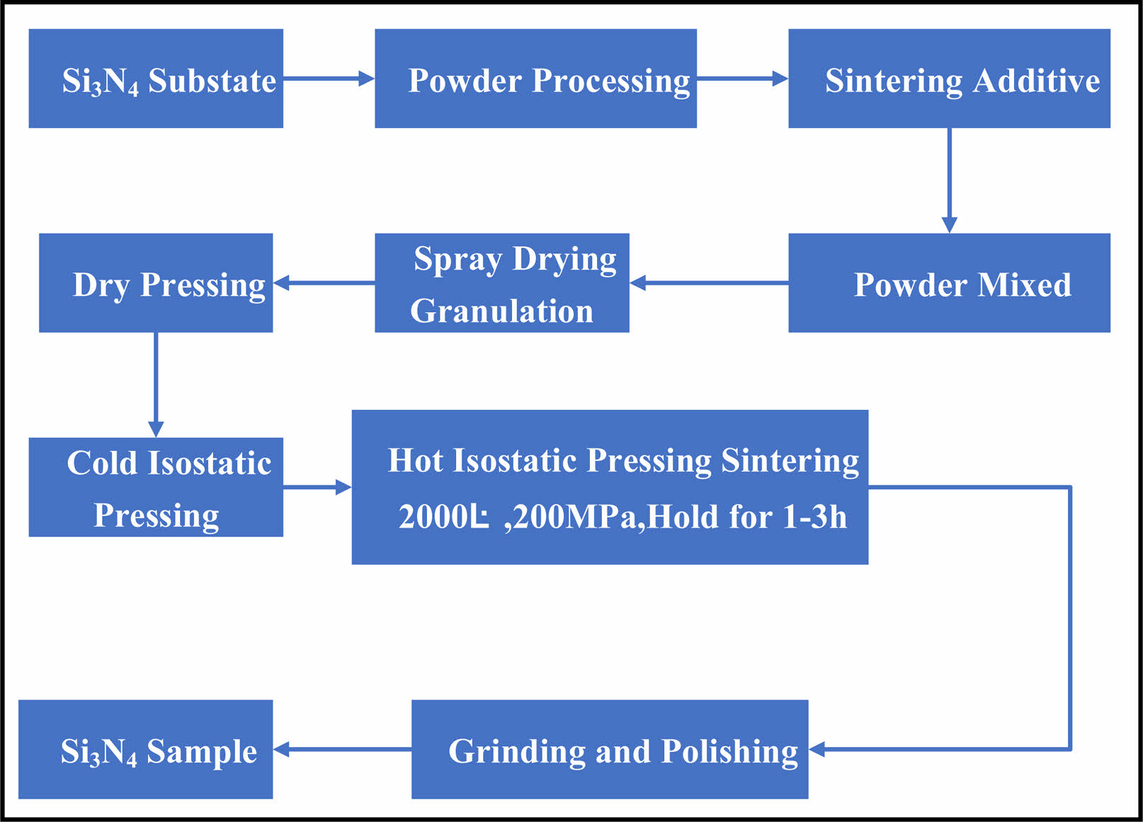
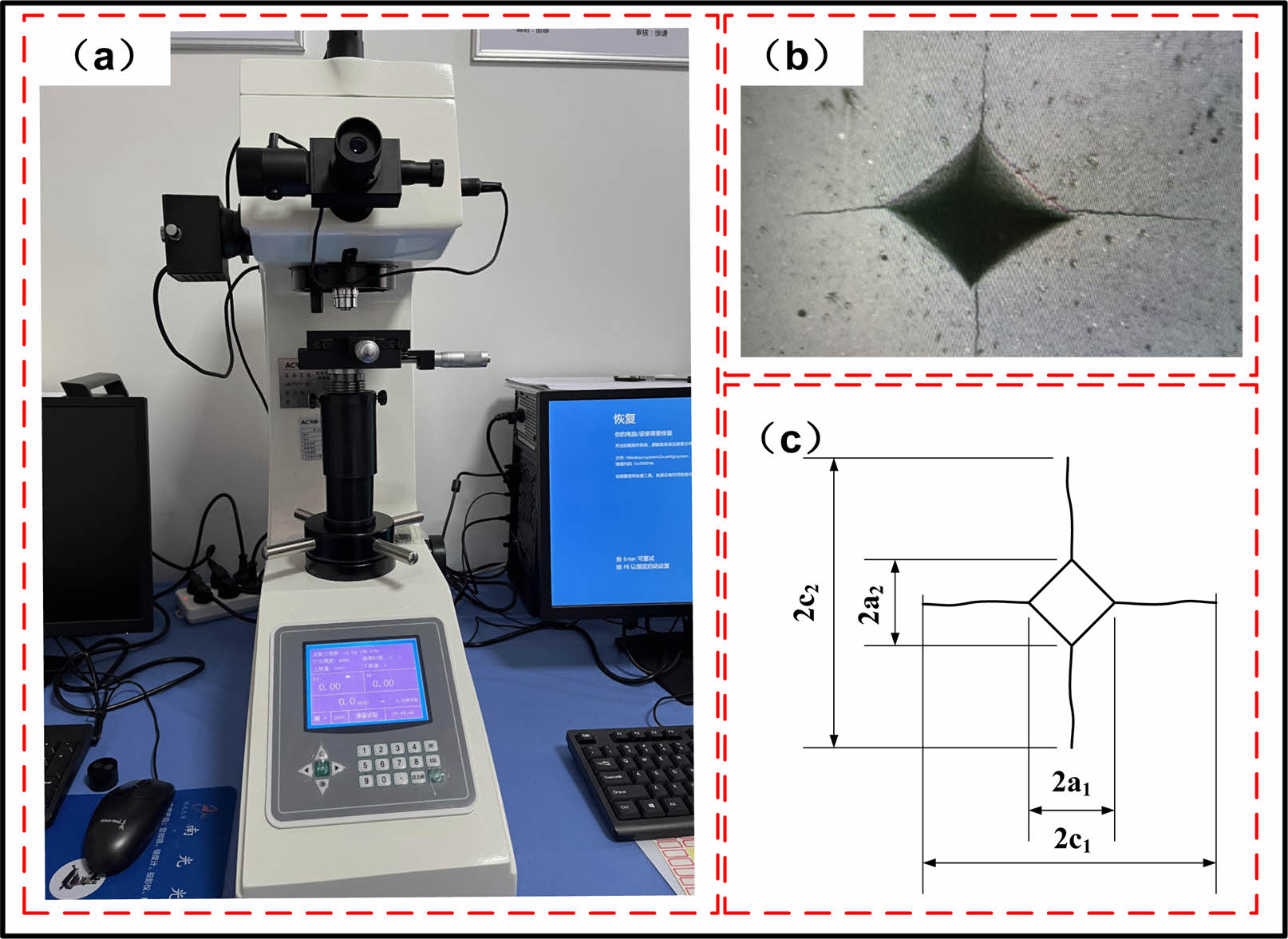
The fracture toughness test sample of silicon nitride ceramics was prepared by Dalian Ecanor New Materials Co., LTD. The specific preparation process is shown in Fig, 1. The HVS-50 semi-automatic micro Vickers hardness tester produced by Suzhou Nang guang Optical Co. LTD., as shown in Fig. 2a, is used as the test equipment. The specific experimental procedure is to apply HV10 load to the surface of polished silicon nitride sample by using the regular quadrigonal diamond indenter of Vickers hardness tester. Until the four corners of the indentation produce obvious cracks (Fig. 2b), then the indentation size and crack length are measured (Fig. 2c), and finally the fracture toughness KIC of the material is calculated by combined with the test load and the elastic modulus of the silicon nitride ceramic material.
Experimental data processing
Vickers hardness
Vickers hardness is calculated by formula (1) according to ASTM E384-16

Where: HV is the Vickers hardness of the sample (Kg/mm2); P is the load applied by the diamond indenter (Kg); a is the average diagonal length of the indentation (mm), which can be expressed as:

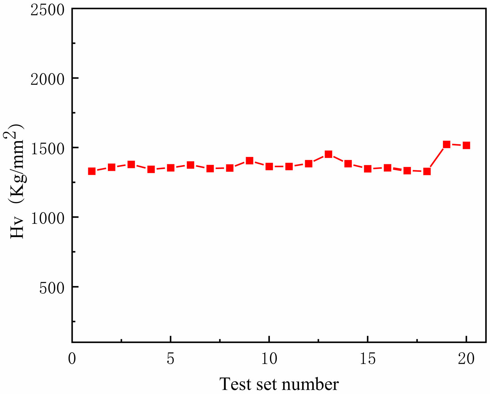
This test adopts HV10 load to test 20 groups of data, and the calculation result of HV according to formula (1) is shown in Fig. 3. The average value is 1380.57 Kg/mm2.
Fracture toughness
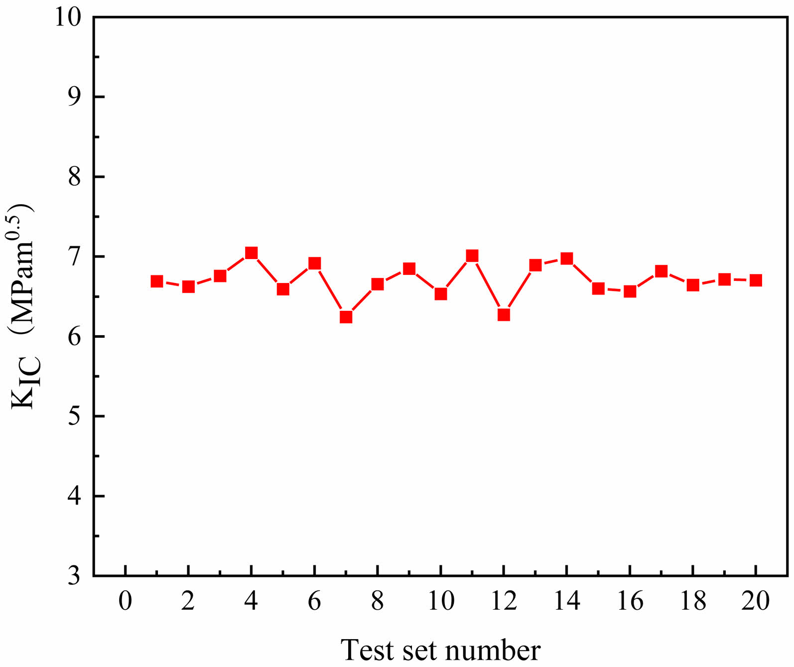
Table 1 shows five classical fracture toughness calculation formulas of ceramic Vickers indentation method, among which JIS R1607, Anstis and Lawn formula models are the same, only the coefficients are different. The 20 groups of data tested have an average crack indentation size ratio 2c/2a=2.28, the maximum crack indentation size ratio is 2.56, and the minimum crack indentation size ratio is 1.82. Therefore, Formula KIC - Niihara, whose crack indentation dimension ratio requirement is 3.5≥2c/2a≥1.25, is selected to calculate the fracture toughness, in which the value of HV is adopted from the above experiment, and the calculation results are shown in Fig. 4. The average fracture toughness K͞͞IC=6.71MPam0.5 and standard deviation s=0.216 MPa·m0.5 were further calculated, which met the requirement of standard deviation less than 0.3 MPa·m0.5 in Appendix C of ISO 21618.
|
Fig. 1 Sample preparation process |
|
Fig. 2 Vickers indentation test equipment, surface topography of silicon nitride specimen after indentation and dimensional measurement diagram. |
|
Fig. 3 Calculated HV data. |
|
Fig. 4 Calculated KIC data. |
|
Table 1 Fracture toughness calculation formula of ceramic Vickers indentation method. |
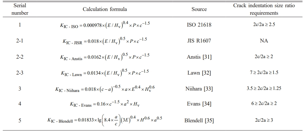
The maximum tensile stress generated in the service process of silicon nitride full ceramic bearing will lead to the initiation of secondary surface cracks near the main surface cracks. Obviously, different main surface crack parameters and service conditions will produce different maximum tensile stresses. Therefore, in order to explore the maximum tensile stress generated by different main surface crack parameters and rolling contact between silicon nitride ring raceway and silicon nitride ball under service conditions, The joint simulation of ABAQUS and Franc3D was carried out.
Joint simulation process
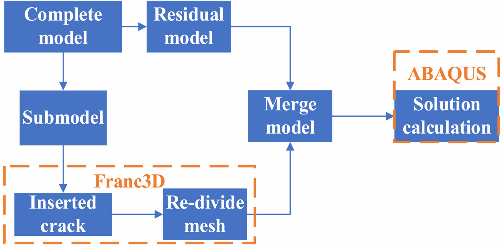
In this paper, two finite element software ABAQUS and Franc3D are used for joint simulation. Firstly, a complete finite element model of the rolling contact between the inner ring of silicon nitride ceramic and the silicon nitride ceramic ball was established in ABAQUS, and the mesh was divided to set the boundary. Then, the submodel of the ring raceway was extracted in Franc3D and inserted into the surface main crack. Finally, after re-dividing the grid, the model is combined and ABAQUS is used to solve the stress and strain of the output tensile stress data generated by rolling contact. The specific process is shown in Fig. 5.
Joint simulation finite element model and material property setting
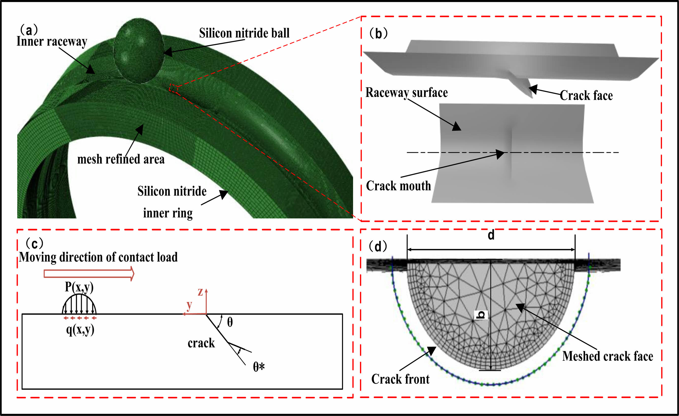
Joint simulation with silicon nitride rolling elements and silicon nitride inner ring raceway rolling contact as the simulation research object. The finite element (FE) model and force situation are shown in Fig. 6. Fig. 6a shows the Joint simulation finite element model. In order to improve the calculation accuracy, the area near the crack is treated with mesh precision technology. Fig. 6b is a locally enlarged view near the crack, which shows the precise location of the crack in the raceway. Fig. 6c is the force diagram of the raceway surface of the ring. The raceway surface is simultaneously subjected to the positive pressure of the vertical raceway surface caused by the rolling contact of the silicon nitride ceramic ball and the friction-pulling force of the same rolling direction. In addition, θ in the figure is the initial crack Angle. Fig. 6d is the crack grid view reconstructed by Zhi da Ren et al. [36] using the geometric characteristics of cracks on the raceway surface measured by experiments, where d is the initial crack width and b is the initial crack depth. The JH-2 constitutive model is adopted for joint simulation of silicon nitride material, and the parameter Settings are shown in Table 2.
Results and analysis of joint simulation
Influence of initial inclination Angle of main surface crack on inner raceway surface on maximum tensile stress of rolling contact
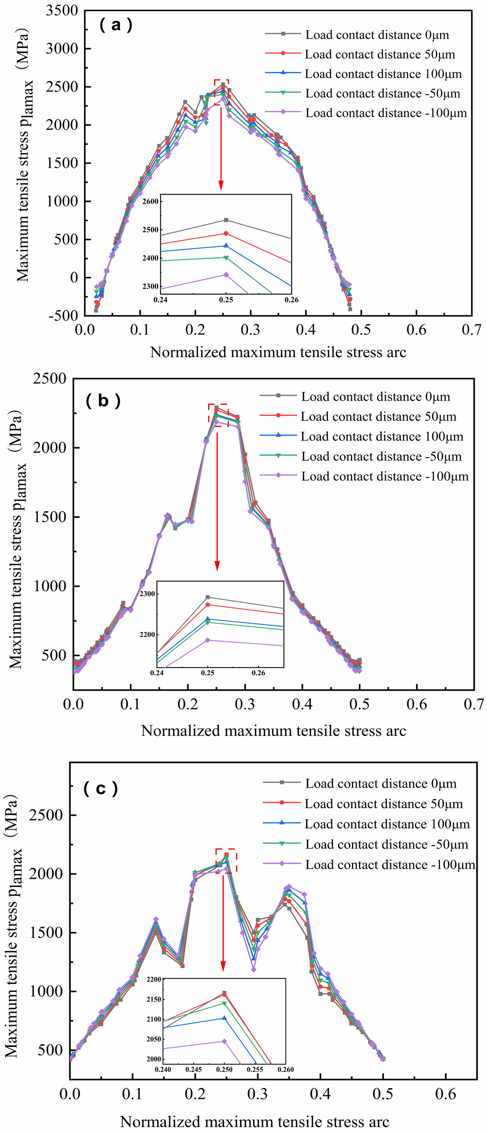
In order to investigate the influence of initial inclination Angle of surface main crack on the maximum tensile stress of rolling contact between silicon nitride ceramic ball and inner ring with surface main crack in raceway, The rolling contact model of silicon nitride ceramic inner ring raceway and silicon nitride ceramic ball with surface main cracks with initial depth b=0.15 mm, initial width d=0.2 mm and initial inclination θ being 30°, 60° and 90° respectively, was established. The maximum radial load Qm=5000N was applied and the friction coefficient f=0.05 was set. The influence of main crack Angle on the maximum tensile stress of rolling contact was studied by joint simulation.
As shown in Fig. 8(a), 8(b) and 8(c), they are the maximum tensile stress curves at different load contact distances near the surface main crack at θ=30°, θ=60° and θ=90° respectively. In order to facilitate expression, the circular arc where the maximum tensile stress is located is normalized, and the horizontal coordinate of each figure is the semi-circular arc of the maximum tensile stress. The location of each load contact distance is shown in Fig. 7, and it can be seen that the maximum tensile stresses in rolling contact at different load contact distances with different surface main crack inclinations are small, and the largest maximum tensile stresses are all at 0 μm load contact distance, and the smallest maximum tensile stresses are all at -100 μm load contact distance. When the rolling contact distance is -100 μm, on the one hand, the depression caused by the contact load is the smallest from the crack, on the other hand, the friction caused by the rolling body is directed to the left, and the depression caused by the friction will pull the crack to make the crack opening larger, which will reduce the depth of the depression. When the rolling contact distance 0 μm, the same one hand from the crack nearest contact load caused by the largest depression, on the other hand, the maximum rolling contact tensile stress generated in the contact ellipse along the rolling direction of the front, so at this time by the frictional action of the depression caused by the crack mouth no longer smaller instead of making the crack mouth squeeze smaller, which in turn will increase the depth of depression. The deeper the depression, the greater the maximum tensile stress of rolling contact, the shallower the depression, the smaller the maximum tensile stress of rolling contact, so this phenomenon will be produced. When θ=30°, the maximum tensile stress of the load contact distance -100 μm is reduced by 7.61% compared with the maximum tensile stress of the load contact distance 0μm; when θ=60°, the maximum tensile stress of the load contact distance -100 μm is only reduced by 4.56% compared with the maximum tensile stress of the load contact distance 0 μm; when θ=90°, the maximum tensile stress of the load contact distance -100 μm is reduced by 5.64%. The maximum tensile stress decreases with the increase of the initial inclination of the main crack. The maximum tensile stress at the initial inclination of the surface main crack θ=60° decreases by 9.56% compared with that at θ=30°, and the maximum tensile stress at the initial inclination of the surface main crack θ=90° decreases by 14.7% compared with that at θ=30°.
Influence of initial depth of main surface crack on the surface of inner ring raceway on maximum tensile stress of rolling contact
The influence of the initial depth of surface main crack on the maximum tensile stress of rolling contact between the silicon nitride ceramic ball and the inner ring with surface main crack in the raceway was investigated. The rolling contact model of silicon nitride ceramic inner ring raceway and silicon nitride ceramic ball with surface main cracks of initial width d=0.2 mm, initial inclination θ=30° and initial depth b of 0.1 mm, 0.15 mm and 0.2 mm, respectively, was established. The maximum radial load Qm=5000N was applied and the friction coefficient f=0.05 was set. The effect of initial crack depth on the maximum tensile stress of rolling contact was studied by joint simulation.
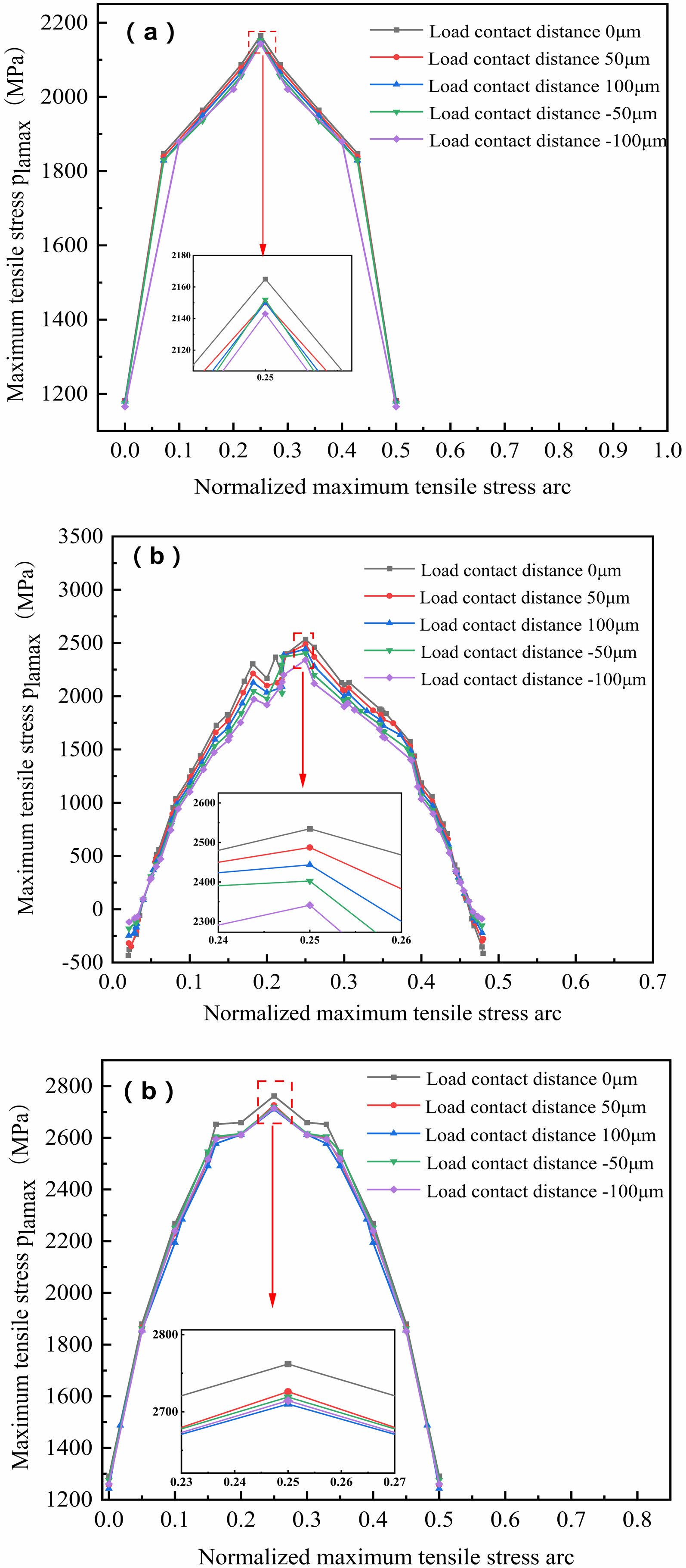
Fig. 9(a), 9(b) and 9(c) show the maximum tensile stress curves at different load contact distances near the surface main crack when b=0.1 mm, b=0.15 mm and b=0.2 mm, respectively. It can be seen that when the initial depth of the main crack is different, the maximum tensile stress of the rolling contact at different load contact distances is also small, and the maximum tensile stress is also at the load contact distance 0 μm, and the minimum and maximum tensile stress is also at the load contact distance -100 μm. When b=0.1 mm, the maximum tensile stress of the load contact distance -100 μm is reduced by 1.01% compared with the load contact distance 0 μm; when b=0.15 mm, the maximum tensile stress of the load contact distance -100 μm is only reduced by 7.61% compared with the load contact distance 0 μm; when b=0.2 mm, the maximum tensile stress of the load contact distance -100 μm is reduced by 1.87% compared with the load contact distance 0 μm. In addition, the maximum tensile stress increases with the increase of the initial depth of the surface main crack. The maximum tensile stress at the initial depth of the surface main crack b=0.15 mm is 17.04% higher than that at the initial depth of the surface main crack b=0.1 mm, and the maximum tensile stress at the initial depth of the surface main crack b=0.2 mm is 27.57% higher than that at the initial depth of the surface main crack b=0.1 mm.
Effect of rolling contact friction coefficient on maximum tensile stress
In order to investigate the effect of rolling contact friction coefficient on the maximum tensile stress of rolling contact between silicon nitride ceramic ball and raceway inner ring with surface main crack, a rolling contact model of silicon nitride ceramic ball and raceway inner ring with initial depth b=0.15 mm, initial width d=0.2 mm, and initial inclination θ=30° was established. The maximum radial load Qm=5000N was applied, and the friction coefficients f were set to 0.05, 0.07 and 0.09, respectively. The influence of rolling contact friction coefficient on the maximum tensile stress of rolling contact was studied jointly.
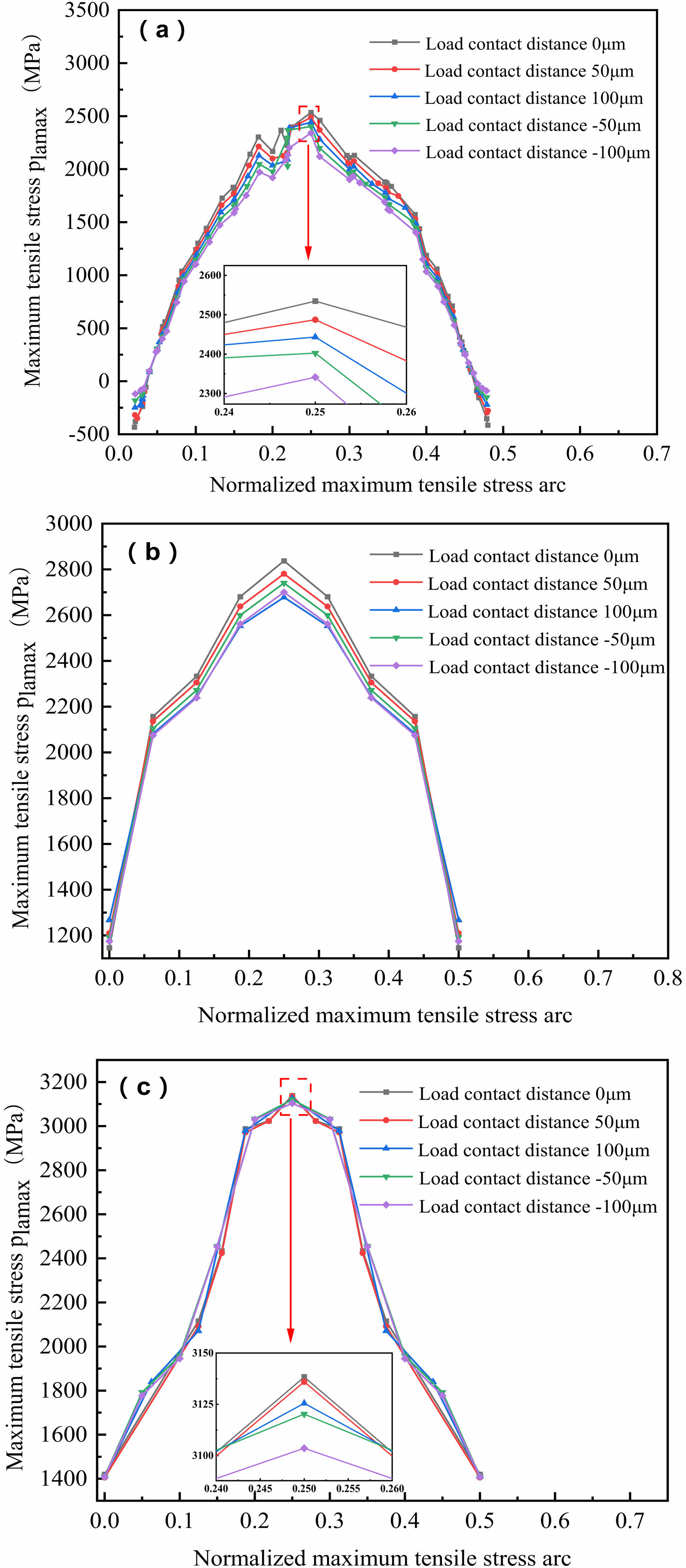
Fig. 10(a), 10(b) and 10(c) show the maximum tensile stress curves at different load contact distances near the surface main crack at f=0.05, f=0.07 and f=0.09, respectively. It can be seen that when the rolling contact friction coefficient is different, the difference of the maximum tensile stress of the rolling contact at different load contact distances is also small. The maximum tensile stress is also at the load contact distance 0 μm, and the minimum and maximum tensile stress is also at the load contact distance -100 μm,when f=0.05, the maximum tensile stress of load contact distance -100 μm is reduced by 7.61% compared with the maximum tensile stress of load contact distance 0 μm,when f=0.07, the maximum tensile stress of load contact distance -100 μm is only reduced by 5.63% compared with load contact distance 0 μm,when f=0.09, the maximum tensile stress of the load contact distance -100 μm is only 1.02% less than that of the load contact distance 0μm.In addition, the maximum tensile stress increases with the increase of rolling contact friction coefficient, where the rolling contact friction coefficient a f=0.07 is 13.13% higher than the maximum tensile stress at b f=0.05, and the rolling contact friction coefficient c f=0.09 is 25.24% lower than the maximum tensile stress at d f=0.05.
Brief summary
The larger the maximum tensile stress is, the more favorable the initiation of secondary surface cracks, and the initiation and propagation of cracks is the key to causing spalling failure. Therefore, in order to improve the spalling fatigue life of silicon nitride bearing rings, the following conclusions can be made from the above research and analysis:
1. In the processing and manufacturing process of silicon nitride bearing rings should try to avoid the production of small initial inclination surface main cracks.
2. In the service process of silicon nitride ceramic, the main crack on the raceway surface will inevitably continue to expand, so the silicon nitride ceramic bearing should be applied to the condition where the surface main crack expansion is slower, so as to slow down the increase in the surface main crack depth.
3. In the service process of silicon nitride ceramic should be used as much as possible rolling contact friction coefficient of smaller lubrication.
|
Fig. 5 Joint simulation flowchart |
|
Fig. 6 FE model, Local zoom view near crack, Force diagram and Crack meshed model |

|
Fig. 7 Schematic diagram of rolling contact load contact distance |
|
Fig. 8 The maximum tensile stress of rolling contact with different load contact distance near the main crack with different crack inclination Angle. (a) θ=30°. (b) θ=60°. (c) θ=90°. |
|
Fig. 9 The maximum tensile stress of rolling contact with different load contact distance near the main crack with different crack depth. (a) b=0.1 mm. (b) b=0.15 mm. (c) b=0.2 mm. |
|
Fig. 10 The maximum tensile stress of rolling contact at different load contact distance near the main crack with different friction coefficient. (a) f=0.05. (b) f=0.07. (c) f=0.09. |
Initiation of secondary surface cracks
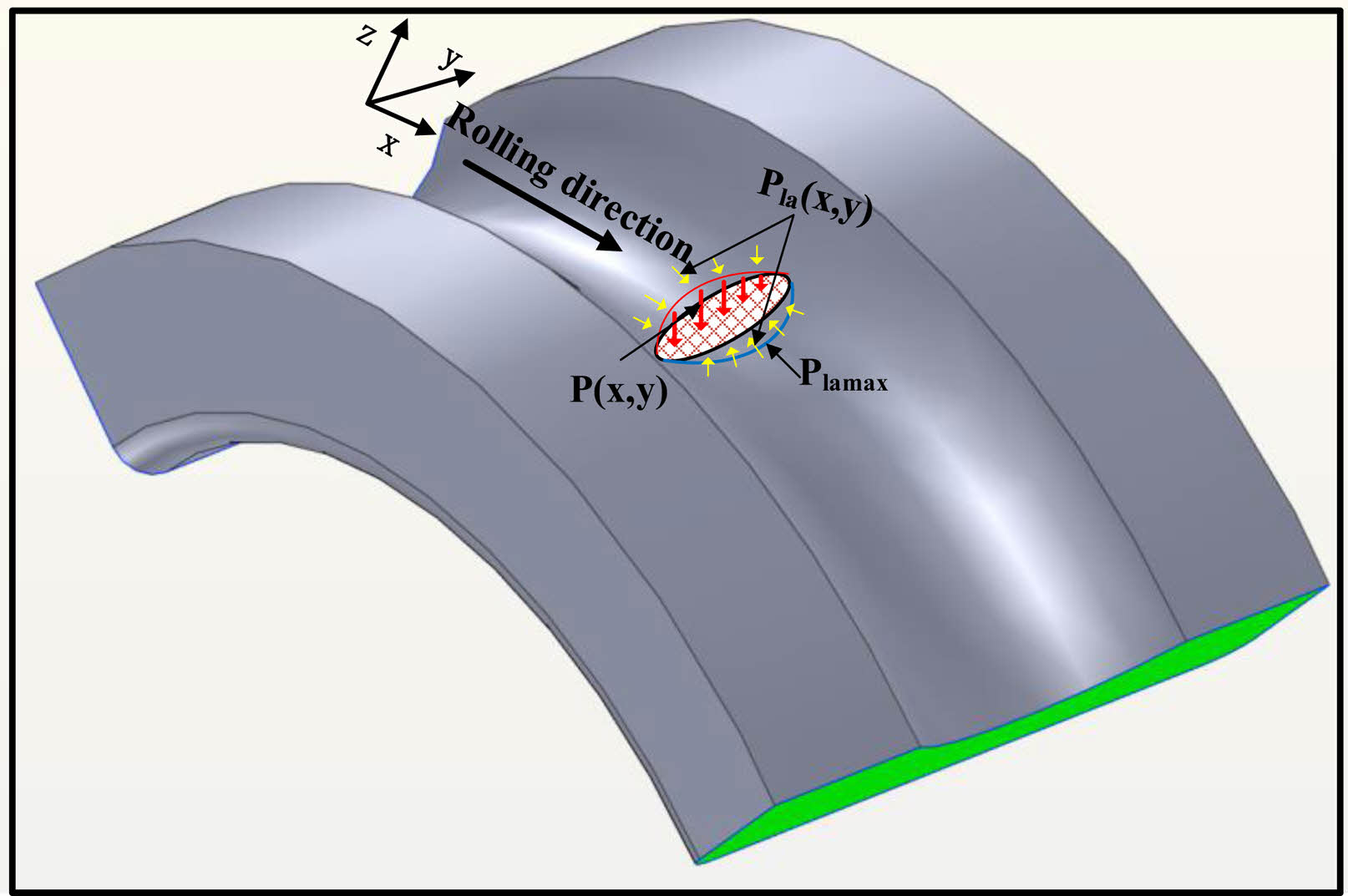
As shown in Fig. 11, in the actual rolling contact, compressive stress and compressive deformation will occur in the contact ellipse region of the contact surface due to the action of load. Therefore, tensile stress can occur outside the contact ellipse due to compressive deformation in the contact ellipse. The results show that due to the rolling friction force, the maximum tensile stress is not produced at the edge of the elliptic contact area during static contact, but near the edge. In addition, silicon nitride material is a typical hard and brittle material, and its tensile strength is much lower than the compressive strength. Therefore, for silicon nitride materials, excessive can easily lead to the initiation of contact surface cracks. Experimental studies [37] have shown that when the maximum tensile stress of silicon nitride rolling contact exceeds 1.84 Gpa, crack initiation will occur.
Calculation of critical initial size of secondary surface crack
The stress intensity factor of crack front caused by tensile stress was given in literature [38] as follows:

Where, is the initial depth of the initiation crack, is the initial width of the initiation crack, and is the angular position of the leading edge of the initiation crack, when the length-diameter ratio  .
.

When the ratio of length to diameter is  .
.

Therefore, determining the critical initial size of the initiation crack in the rolling contact process means that the initiation crack no longer occurs instability expansion, and the stress intensity factor of the crack front should be satisfied:

The value of KIC in the formula is obtained from the above experiments.
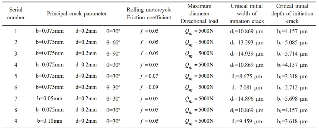
In this paper, the final shape 2bi / dj = 0.765 of crack length-diameter ratio given in literature [39] is adopted. Therefore, the calculation is performed when the length-diameter ratio  is adopted in equation (3). In addition, the literature also pointed out that when the length-diameter ratio 2bi / dj = 0.765, the KappIC value of φ = 0° and φ = 90° is equal. Therefore, in this paper, φ = 0° is used to calculate the crack front point of the contact surface. By substituting the maximum tensile stress generated under rolling contact in section 3, the critical initial size of the initiation crack can be solved by connecting the vertical (3) - equation (4). The calculated main crack parameters and the initial size of the initiation crack under working conditions are shown in Table 3.
Brief summary
In this section, the critical initial size of secondary surface crack initiation under different main crack parameters and different rolling friction coefficients is calculated based on the KIC fracture toughness data obtained from test experiments and previous theoretical research results, which provides a data basis for further study and calculation of spalling fatigue life of silicon nitride full ceramic bearings.
|
Fig. 11 Rolling contact stress diagram. |
|
Table 3 The main crack parameters and the critical initial size of the initiation crack under the working condition |
In this paper, a three-dim1ensional finite element rolling contact model of silicon nitride ceramic inner ring and silicon nitride ceramic ball with surface main crack in raceway was established, and the joint simulation of ABAQUS and Franc3D was carried out. The rolling contact tensile stress of inner ring raceway with different initial inclination surface main crack, inner ring raceway with different initial depth surface main crack and different rolling contact friction coefficient were calculated for different rolling load contact distance, and the regularity of the calculation results was analyzed. Then, the critical initial size of rolling contact initiation crack under various main crack parameters and rolling contact friction coefficient is calculated by using the calculated maximum tensile stress and the fracture toughness data of silicon nitride material obtained from test experiments. The following conclusions are drawn:
1. When the inner raceway contains surface main cracks with different initial depths and different initial angles and different rolling friction coefficients, the difference of maximum rolling contact tensile stress is small for different load contact distances, and the maximum tensile stress is maximum at load contact distance 0 μm, and minimum at load contact distance -100 μm.
2. The maximum tensile stress decreases with the increase of the initial inclination Angle of the surface main crack, increases with the increase of the initial depth of the surface main crack, and increases with the increase of the rolling contact friction coefficient. In the process of manufacturing silicon nitride bearing rings, the main crack on the surface of small initial inclination Angle should be avoided as far as possible. In the service process of silicon nitride ceramics, the lubrication mode with smaller rolling contact friction coefficient and the condition of slower surface main crack growth should be selected as far as possible.
3. The initial size of secondary surface crack initiation under different surface main crack parameters and different rolling friction coefficients is calculated, which provides a data basis for further study and calculation of spalling fatigue life of silicon nitride full ceramic bearings.
The authors would like to thank all the reviewers for their constructive comments. This work was supported by the Key Project of National Natural Science Foundation of China (Joint Fund) under grant U23A20631and Applied Basic Besearch Project Of Liaoning Province under grant 2022JH2/101300216.
RCF : Rolling contact fatigue
FE : Finite element
The authors declare no competing interests.
- 1. J. Sun, Z. Zhang, Z. Xia, X. Fang, R. Guan, G. Zhang, and J. Yao, J. Ceram. Process. Res. 24 (2023) 541-553.
-

- 2. L.M. Keer, and M.D. Bryant, Asme J. Lubr. Tech 105 (1983) 198-205.
-

- 3. R.S. Zhou, H.S. Cheng, and T. Mura, Journal of Tribology 111 (1989) 605-613.
-

- 4. Z.J. Liu, and L. He SQ, in (Beijing: China Machine Press, 2006)
- 5. Peter, Gloeckner, Matthias, Martin, Michael, and Flouros, Tribol T 60[6] (2016) 1148-1158.
-

- 6. J. Belinha, J.M.C. Azevedo, L.M.J.S. Dinis, and R.M.N. Jorge, Eng. Comput. 14 (2017).
-

- 7. L. Cui, X. Wang, H. Wang, and J. Ma, IEEE Trans. Instrum. Meas. PP (2019) 1.
-

- 8. L. Cui, X. Wang, H. Wang, and N. Wu, IEEE Access (2019) 1.
-

- 9. D. Wu, H. Wang, H. Liu, T. He, and T. Xi, Applied Sciences 9 (2019) 3246.
-

- 10. H. Guo, D.H. Yoon, and D.W. Shin, J. Ceram. Process. Res. 6 (2005) 321-325.
- 11. H. Kawaoka, T. Kusunose, Y.H. Choa, T. Sekino, and K. Niihara, J. Ceram. Process. Res. 2 (2001) 51-53.
- 12. B. Li, H. Ma, X. Yu, T. Zeng, X. Guo, and B. Wen, Arch. Appl. Mech. 89 (2019) 1-28.
-

- 13. C. Vieillard, Int. J. Fatigue 96 (2016) 283-292.
-

- 14. D. Ma, J. Wang, and L. Sun, J. Am. Ceram. Soc. 100 (2017) 2296-2308.
-

- 15. L. Cui, Z. Jin, J. Huang, and H. Wang, IEEE Access 7 (2019).
-

- 16. L. Sun, D. Ma, L. Wang, X. Shi, J. Wang, and W. Chen, Eng. Fract. Mech. 197 (2018) 151-159.
-

- 17. P. Zhao, M. Hadfield, Y. Wang, and C. Vieillard, Wear 257 (2004) 1047-1057.
-

- 18. W. Karaszewski, Tribol. Int. 41 (2008) 889-895.
-

- 19. M.J. Komanduri, Wear (1998).
- 20. R.N. Katz and J.G. Hannoosh, Mater. Des. 8 (1987) 108-112.
-

- 21. E.V. Zaretsky, Y.P. Chiu, and T.E. Tallian, Journal of Materials Engineering 11 (1989) 237-253.
-

- 22. Y. Wang, and M. Hadfield, 1999, pp. 1284-1292.
-

- 23. Y. Wang and M. Hadfield, WEAR 243[1-2] (2000) 167-174.
-

- 24. Y. Wang and M. Hadfield, WEAR 243[1] (2000) 157-166.
-

- 25. Y. Wang and M. Hadfield, WEAR 250 (2001) 282-292.
-

- 26. Y. Wang and M. Hadfield, WEAR 253[9-10] (2002) 975-985.
-

- 27. Y. Wang and M. Hadfield, Tribology Series 41[03] (2003) 349-358.
-

- 28. Y. Wang and M. Hadfield, WEAR 254[7-8] (2003) 597-605.
-

- 29. Y. Wang and M. Hadfield, WEAR 256[1-2] (2004) 208-219.
-

- 30. P. Zhao, M. Hadfield, Y. Wang, and C. Vieillard, Wear 261 (2006) 390-397.
-

- 31. G.R. Anstis, P. Chantikul, B.R. Lawn, and D.B. Marshall, J. Am. Ceram. Soc. 64 (1981) 533-538.
-

- 32. B.R. Lawn, A.G. Evans, and D.B. Marshall, J. Am. Ceram. Soc. (1980).
- 33. K. Niihara, R. Morena, and D.P.H. Hasselman, Journal of Materials Science Letters 1 (1982) 13-16.
-

- 34. A.G. Evans and E.A. Charles, J. Am. Ceram. Soc. (1976).
- 35. J.E. Blendell, Massachusetts Institute of Technology 123 (1979) 617-626.
- 36. Z. Ren, B. Li, and Q. Zhou, Wear 506 (2022) 204459.
-

- 37. P. Zhao, M. Hadfield, Y. Wang, and C. Vieillard, Wear 257 (2004) 1047-1057.
-

- 38. M. Janssen, J. Zuidema, and R. Wanhill, CRC Press, (2004).
-

- 39. A.E. Piotrowski and M.J. O'Brien, Fatigue Fract. Eng. Mater. Struct. 29 (2006) 558-572.
-

 This Article
-
2024; 25(4): 694-703
Published on Aug 31, 2024
- 10.36410/jcpr.2024.25.4.694
- Received on Jun 14, 2024
- Revised on Jul 21, 2024
- Accepted on Jul 31, 2024
 Services
- Abstract
introduction
vickers indentation experimental on fracture toughness of silicon nitride ceramics
joint simulation of maximum tensile stress of rolling contact with main surface crack
initiation of secondary surface cracks and calculation of critical dimensions
conclusion
- Acknowledgements
- Nomenclature
- Conflict of Interest
- References
- Full Text PDF
Shared
 Correspondence to
- Songhua Li
-
aSchool of Mechanical Engineering, Shenyang Jianzhu University, Shenyang 110168, China
cNational-Local Joint Engineering Laboratory of NC Machining Equipment and Technology of High-Grade Stone, Shenyang Jianzhu University, Shenyang 110168, Liaoning, China - E-mail: lisonghua@sjzu.edu.cn


 Copyright 2019 International Orgranization for Ceramic Processing. All rights reserved.