- Comparison of mechanical behavior after thermal shock according to different substrate and coating methods in the SiC coated C/C fiber reinforced composites
Dong Heon Leea,*, Seong Joon Kohb, Soo Bin Baec, Man Young Leec and Kee Sung Leeb,*
aDepartment of Automotive Engineering, Kookmin University, Seoul 02707, Korea
bSchool of Mechanical Engineering, Kookmin University, Seoul 02707, Korea
cAgency for defense development, Daejeon 341876, KoreaThis article is an open access article distributed under the terms of the Creative Commons Attribution Non-Commercial License (http://creativecommons.org/licenses/by-nc/4.0) which permits unrestricted non-commercial use, distribution, and reproduction in any medium, provided the original work is properly cited.
In this study, we investigated the effect of thermal cycling on the mechanical properties of silicon carbide (SiC)-coated carbon/carbon composites fabricated using different techniques. First, we prepared carbon/carbon composites using two fabrication techniques: fiber-rod stacking (RS) and needle punching (NP). Second, each surface of the carbon/carbon composites was coated with SiC using chemical vapor deposition (CVD) or chemical vapor reaction (CVR) to prevent oxidation in air at high temperatures. We prepared three samples (denoted as RS-CVD, NP-CVR, and NP-CVD based on the combined manufacturing and coating methods) and subjected them to 1–6 thermal shock cycles at 1500℃ in air. NP-CVD exhibited the highest oxidation resistance, as indicated by the minimal weight loss after thermal cycling. The coating layer of NP-CVD exhibited a higher density than that of NP-CVR, allowing for effective protection of the carbon/carbon composite from high-temperature oxidation. In addition, NP-CVD exhibited excellent mechanical properties, including hardness, elastic modulus, and indentation strength. Furthermore, the sample showed only a slight decrease in hardness and indentation strength after thermal cycling. These results indicate that carbon/carbon substrates prepared using NP and coated using CVD exhibit excellent thermal and mechanical properties even after thermal cycling in air.
Keywords: Carbon-carbon composite, SiC coating, Thermal shock, Mechanical behavior.
The demand for high-strength and lightweight aerospace components has significantly increased with the growth of the aerospace industry [1-3]. Carbon/carbon composites offer excellent mechanical and lubrication properties owing to the stable covalent bonding of carbon and the high thermal and mechanical performance of carbon fibers. Furthermore, carbon/carbon composites have attracted attention in aerospace rocket launchers owing to their excellent heat and thermal shock resistance at high temperatures [4-6]. These materials can withstand frictional heat at high temperatures and relatively low pressures.
Carbon materials exhibit low ductility, making them susceptible to fracture under mechanical or thermal shock. Therefore, carbon fibers are woven into carbon materials to prevent the destruction of the carbon matrix. Although this can prevent the failure of carbon materials, their application is limited by their rapid oxidation in the presence of oxygen. This can be prevented by introducing an oxidation-resistant coating layer on the surface of the carbon/carbon composites. For example, carbon/carbon composites can be protected from oxygen by coating them with heat-resistant carbides or borides, thereby delaying oxidation [7-9].
However, the coating can cause damage to the composites because of the thermal and mechanical mismatch between the composites and the coating layers [10-12]. The coating layers can be delaminated by damage, thereby decreasing their performance [8]. Loads are inevitably applied to mechanical components as they operate under constrained conditions. Differences in the elastic moduli of the coating and substrate layers can cause critical stress. When mechanical components are subjected to thermal cycling, repeated thermal expansion or contraction in each layer can lead to differences in thermal stresses due to thermal expansion mismatch. A composite reinforced with fibers stacked in different directions can exhibit stress mismatch.
In this study, we prepared carbon/carbon composite substrates using needle punching (NP) [13, 14] and fiber-rod stacking (RS) and investigated the effect of the substrate on the thermal/mechanical properties of the composites. To produce preforms using NP, needles are attached in different directions on the vertical axis, penetrating the thickness of the stacked fiber layers while moving in the vertical direction. This causes the fibers to interlock and bond, thereby enhancing the density of the composites. This process also allows for the rapid production of complex-shaped preforms.
Hf, Ta, and Zr with carbides or nitrides have been coated to prevent oxidation; however, the coating layers are easily delaminated during thermal cycling because of the difference in the properties of the layers and the substrate. Therefore, we selected silicon carbide (SiC) as a protective coating layer for carbon/carbon composites. The difference between the elastic moduli and thermal expansion coefficients of SiC and carbon material in the horizontal direction is relatively low. In our previous studies, we fabricated SiC coatings using chemical vapor reaction (CVR) and chemical vapor deposition (CVD) and investigated their thermal shock and flame resistance, which indicate their resistance to oxidation [15]. However, the thermal shock resistance of SiC-coated composites fabricated using NP has not been studied. In this study, we evaluated the thermal shock resistance of SiC-coated carbon/carbon composites fabricated using NP and RS methods. We performed spherical indentation [11, 12] to evaluate the changes in the mechanical properties before and after thermal cycling.
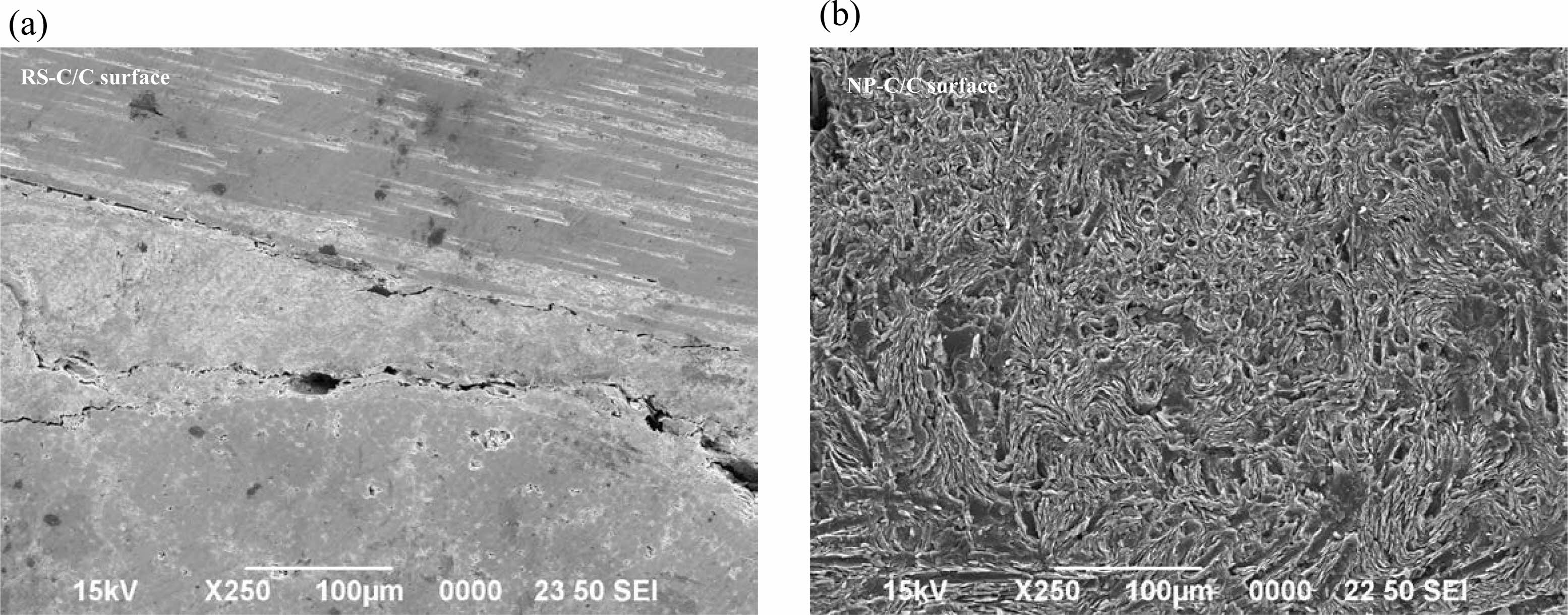
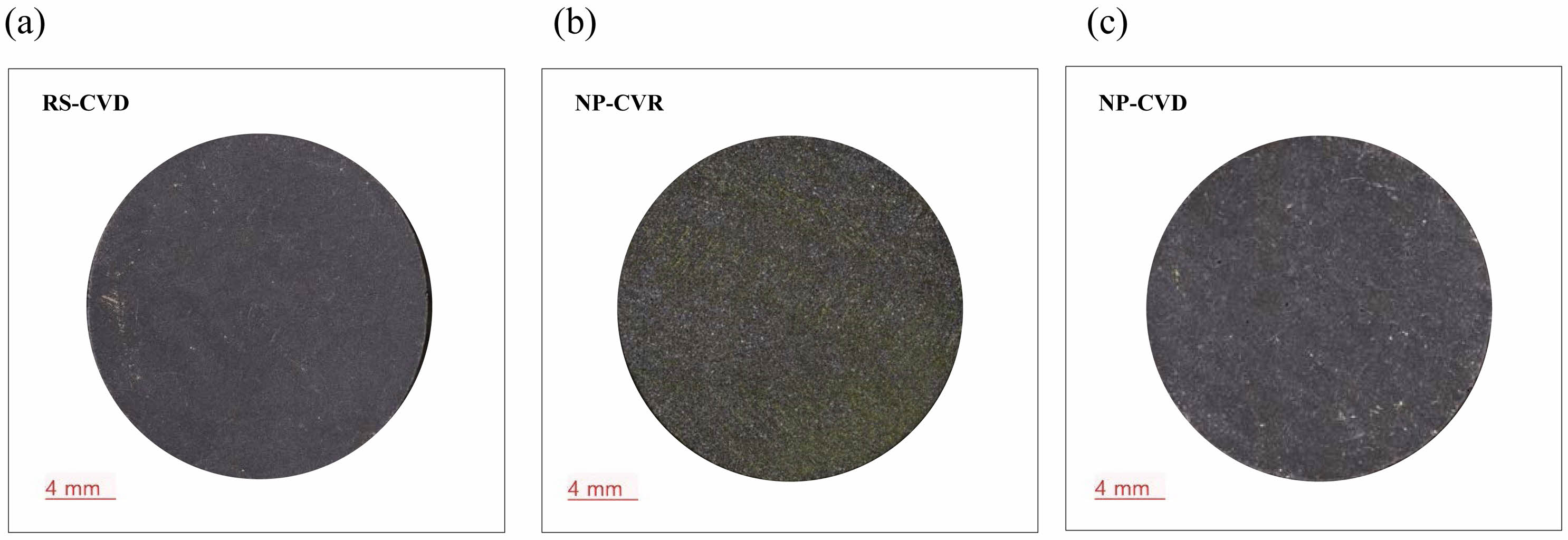
Two types of carbon/carbon fiber-reinforced composites fabricated using two methods (NP and RS) and coated with SiC using different techniques (CVD and CVR) were prepared. The composites are disk-shaped with a diameter of 25 mm and a thickness of 5 mm. For the composites fabricated using the RS process, carbon fibers were stacked in multidimensional directions. The other sample was fabricated using the NP method. Fig. 1 shows the scanning electron microscopy (SEM) images on the surface of the carbon/carbon substrates manufactured using RS (Fig. 1(a)) and NP (Fig. 1(b)). The substrate fabricated using RS showed fibers stacked in different directions. In contrast, fiber entanglement was observed in the substrate fabricated using NP, indicating a relatively high-density morphology. The fabricated samples are denoted as RS-CVD, NP-CVR, and NP-CVD based on the combined substrate fabrication and coating methods. Fig. 2(a) shows the digital photographs of the surfaces of the composite samples. The macroscopic images show that a dense SiC film was formed on the surfaces of the samples. The samples coated using CVD showed higher surface densities than those coated using CVR. The thicknesses of the coating layers were generally uniform, varying from 50 to 100 μm.
The surfaces of the samples were ground sequentially using diamond suspensions with grit sizes of 25, 16, 6, 3, and 1 µm. To ensure uniform grinding, the thickness of the samples was measured after each stage, and the final samples were controlled to have a consistent coating layer thickness.
To compare the hardness of the composites before and after thermal cycling, Vickers hardness tests were performed before and after thermal cycling. A Vickers indenter made of diamond material was brought into contact with the composite surface in air, and a load of P = 1 kgf was applied to induce plastic deformation. The load was carefully controlled to minimize crack formation. After removing the load, the diagonal length d of the diamond-shaped indentation formed on the surface was measured, and the hardness Hv was calculated using the following equation:

After the thermal shock test, no additional flat grinding was performed. Furthermore, to evaluate the mechanical properties of the composites and their changes due to thermal cycling, the samples were subjected to spherical indentation before and after thermal cycling. For the spherical indentation test, a tungsten carbide (WC) sphere with a radius r of 3.98 mm was mounted onto a universal testing machine (Instron 5567, UK). The loading speed was controlled at 0.2 mm/min, and the spherical indenter was brought into contact with the sample surface. Next, a load P of 100-2000 N was applied and removed at the same speed (unloading). The diameter 2a of the indentation formed was measured using an optical microscope, and the indentation stress and strain were calculated as follows [10-12]:

For the thermal shock test, a thermal shock testing machine that allows reciprocating movement of the sample between the interior (high temperature) and exterior (room temperature) of a high-temperature furnace, driven by a mechanical motor, was designed and used. First, the temperature of the high-temperature furnace was increased to a target temperature of 1500℃ at a constant rate of 5℃/min in air and then maintained for the desired duration. Subsequently, the coated composite sample at room temperature was inserted into the hot zone of the furnace using an elevator. After 10 min, the sample was returned to the room temperature zone using the motor to subject it to thermal shock. Thermal cycling, with exposure times of 10 min each for the hot and cold zones, was repeated one to six times.
During the thermal shock test, the size and weight of the specimens were measured after each cycle, and Vickers and spherical indentation tests were conducted. In addition, surface cracks were observed using a digital microscope, and changes in the crystal structure and microstructure after the thermal shock test were analyzed using X-ray diffraction (XRD) and SEM.
|
Fig. 1 Scanning electron microscopy (SEM) images of carbon/carbon fiber composites prepared using (a) fiber-rod stacking (RS) and (b) needle punching (NP) before coating |
|
Fig. 2 Optical micrographs of the coating surfaces of the as-prepared (a) RS-CVD, (b) NP-CVR, and (c) NP-CVD. |
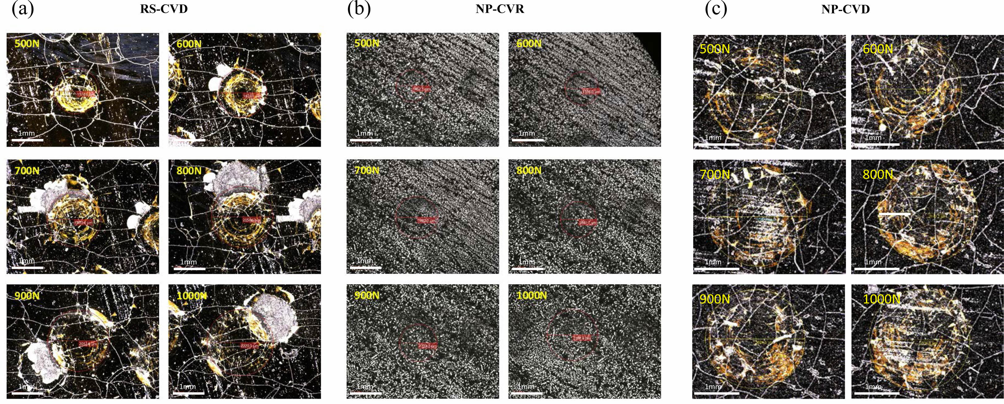
Fig. 3 shows digital micrographs of the indentation on the SiC-coated composites before thermal cycling. The indentation load was increased from 500 to 1000 N in increments of 100 N, and the areas of indentation on the surface were observed using a digital microscope. Fine cracks were observed on the RS-CVD and NP-CVD surfaces after the coating process (Fig. 3(a) and (c)). In addition, the coating layer on RS-CVD was delaminated around the indentation. Under the same load, the size of the indentation recorded on the sample coated using CVR (NP-CVR) was smaller than that of the samples coated using CVD, as shown in Fig. 3(b). In addition, there was no additional damage around the indentation marks, and no cracks were observed on the coating layer, indicating improved mechanical properties compared with those of the samples. However, after six thermal cycles, NP-CVR disintegrated, and its mechanical properties could not be measured. Consequently, it was excluded from further comparative analysis.
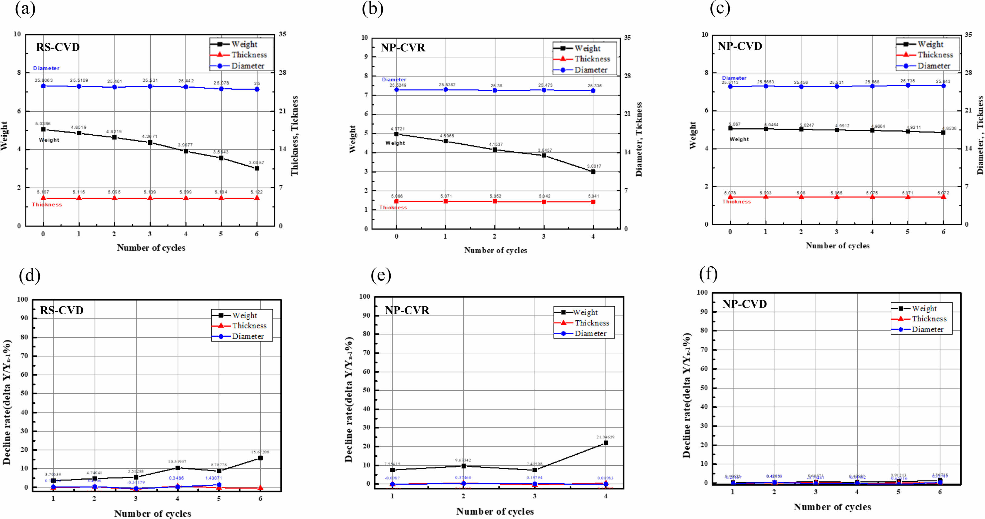
The diameter, thickness, and mass of each sample were measured after thermal cycling (Fig. 4). The three samples showed minimal changes in diameter and thickness but a decrease in weight. The weight decreased continuously with increasing thermal cycles for both RS-CVD and NP-CVR (Fig. 4(a) and (b)), while there was no change in the weight of NP-CVD (Fig. 4(c)). The observed weight loss is attributed to the oxidation of carbon in air, which releases gas, and chipping or delamination of the coating layers. Fig. 4(d)-(f) shows the percentage weight losses of the samples after each thermal cycle. RS-CVD and NP-CVR showed a maximum weight loss of 20%, whereas NP-CVD showed no weight loss, indicating its relatively superior thermal shock resistance.
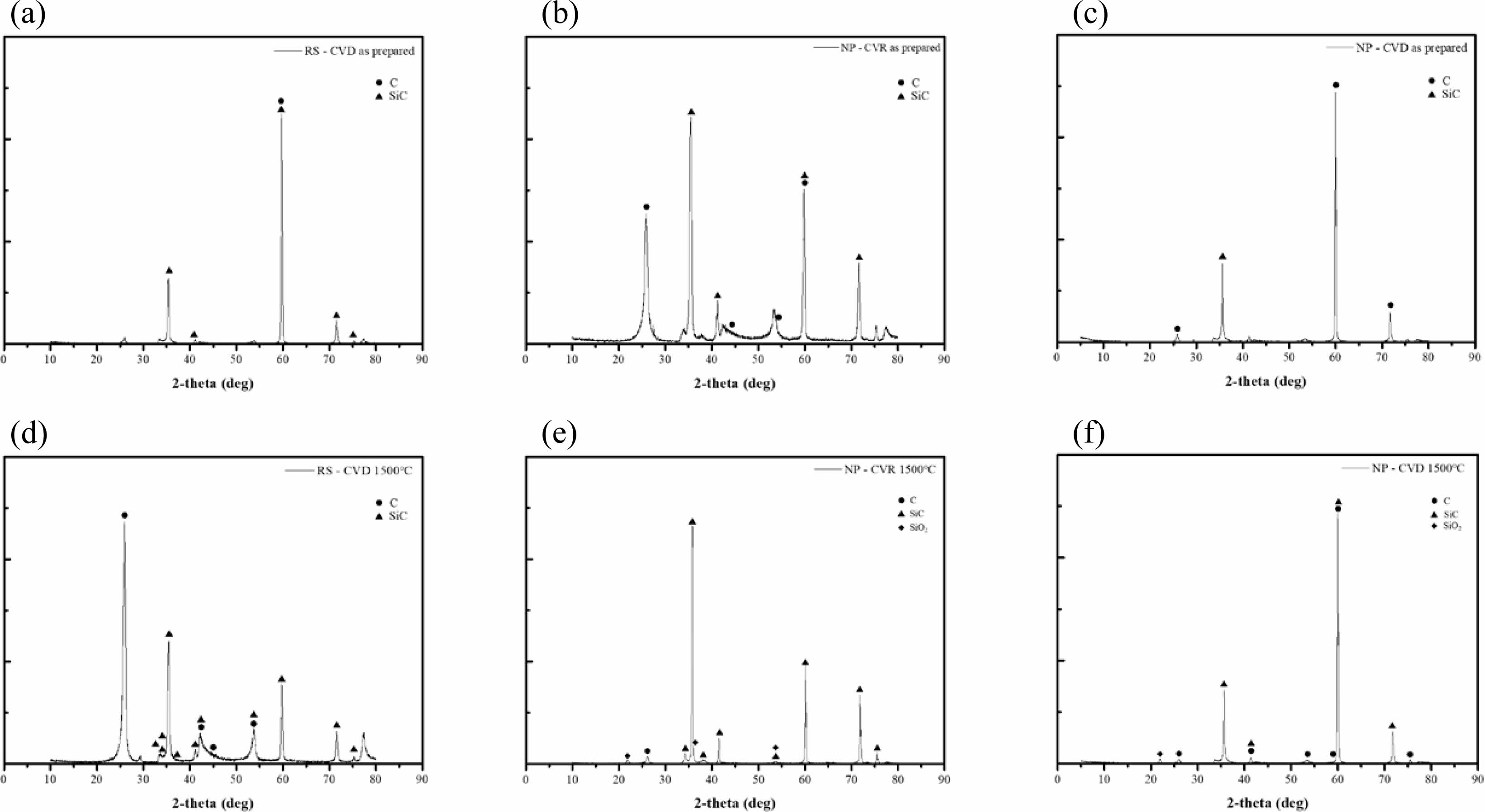
Fig. 5 shows the XRD patterns of the sample surfaces before and after thermal cycling. As shown in Fig. 5(a) and (c), when SiC was coated using CVD (i.e., RS-CVD and NP-CVD), only SiC and carbon phases of the substrate were detected. Oxides formed on the surface were either lost or formed between the substrate and the coating layer due to oxygen penetration through the cracks; thus, no oxide layer was detected. On the other hand, an oxide layer (SiO2) was detected on the NP-CVR surface (Fig. 5(b)), resulting in a further decrease in the weight of the coating layer.
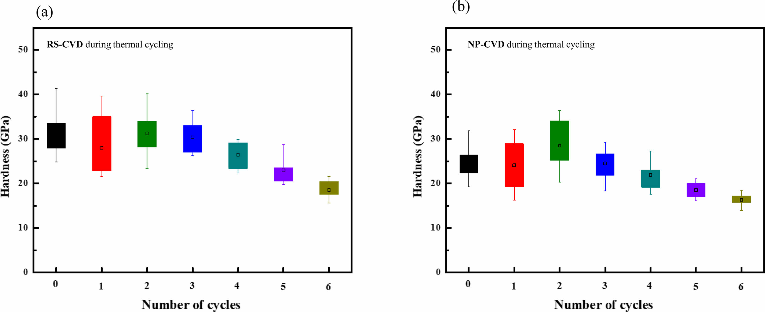
Micro-Vickers hardness tests were conducted after each cycle, and the results are shown in Fig. 6. The NP-CVR specimen was severely damaged after the thermal cycles even though it showed higher mechanical resistance; thus, it was excluded from further analysis. At the beginning of the cycles, RS-CVD and NP-CVD exhibited similar hardness within an error range and showed a similar trend as the number of thermal cycles increased (the hardness decreased with increasing number of cycles). This indicates the occurrence of material degradation during thermal cycling, which is attributed to slight oxidation of the substrate despite the presence of the SiC protective coating layer.
For the samples coated using CVD, cracks on the surface allowed oxygen penetration, resulting in the formation of oxides between the substrate and the coating or on the fiber surface, which can affect the hardness. Notably, the rate of decrease in the hardness of RS-CVD was higher than that of NP-CVD (Fig. 6(a) and (b)). This indicates that the NP-CVD sample exhibited relatively high resistance to thermal shock.
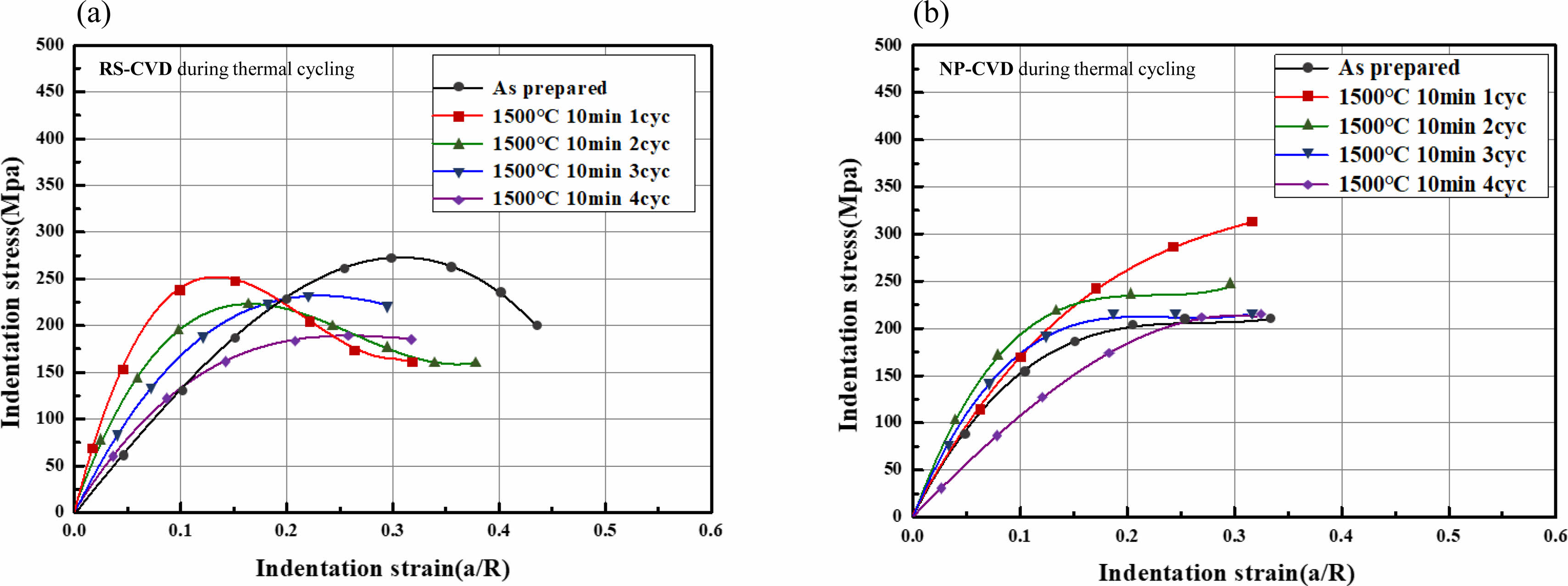
During each thermal cycle, spherical indentation tests were conducted, and the size of the contact area was measured to calculate the indentation stress and strain (Fig. 7). The RS-CVD sample supported higher stress at smaller strains, but the stress decreased as the strain increased. This behavior of the indentation stress–strain curve is consistent with that reported in previous studies [10, 11, 16] and is attributed to the influence of the coating layer at lower load ranges and the substrate at higher load ranges. The RS-CVD samples exhibited a wider dispersion range, which is attributed to the heterogeneity of the substrate. As the number of thermal cycles increased, the stress at the same strain gradually decreased, indicating mechanical property degradation with increasing thermal cycles. The indentation stress–strain curve of the RS-CVD sample decreased more significantly than that of the NP-CVD sample. On the other hand, NP-CVD showed a relatively small scatter of data compared with that of the RS-CVD sample, and the magnitude of changes in the stress–strain curve with thermal cycles was not significant. These results indicate that the NP-CVD sample exhibited less degradation due to thermal shock than the RS-CVD sample.
The Vickers and spherical indentation tests results revealed that the relatively homogeneous substrates produced via NP and coated using CVD (NP-CVD) underwent smaller degradation in mechanical properties after thermal cycling, indicating its high resistance to thermal shock and good mechanical properties.
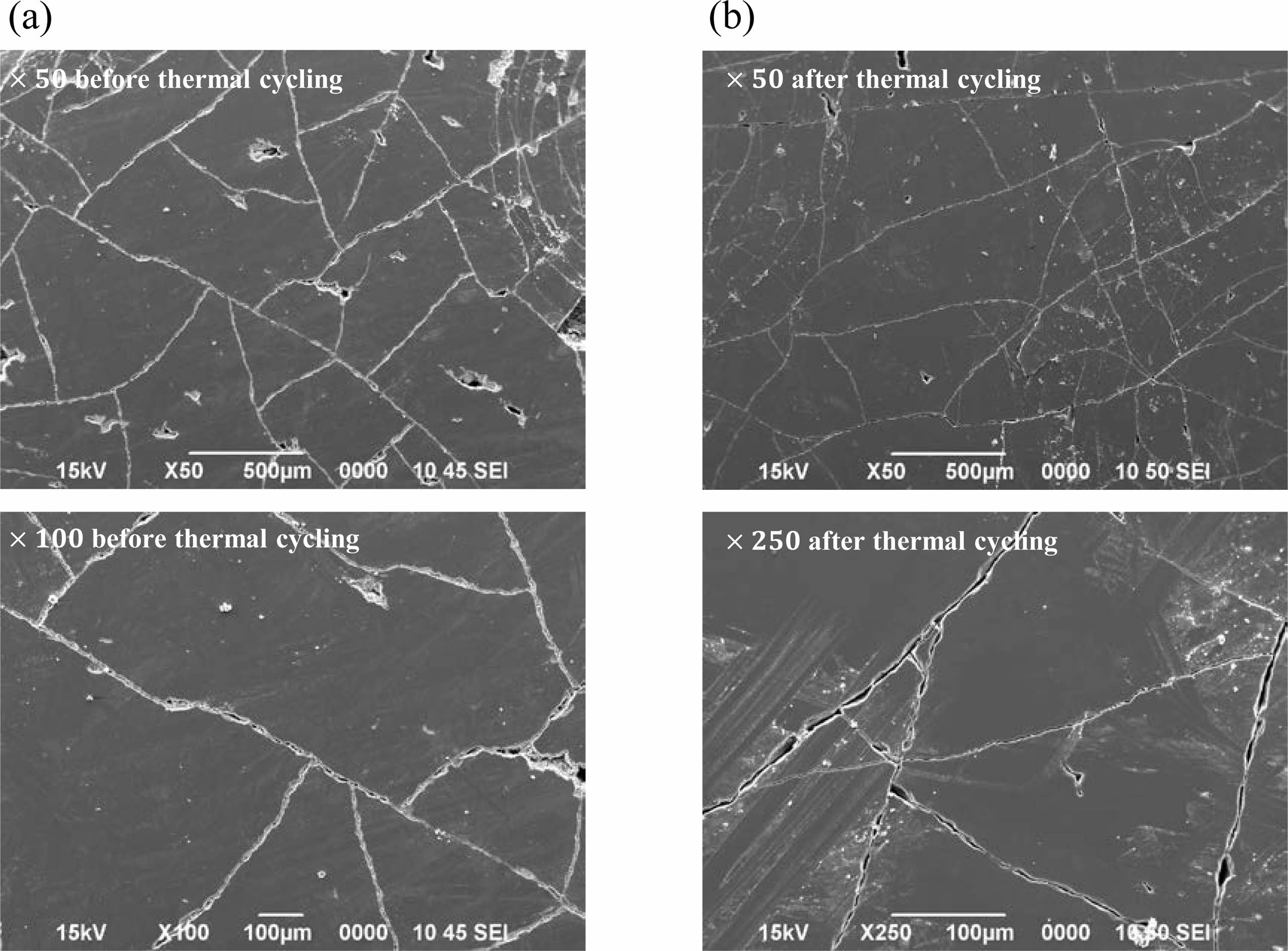
Fig. 8 shows the SEM images of the NP-CVD surface before and after thermal cycling. The crack spacing decreased after the thermal cycles. This result shows that cracks formed on the coating layer of the sample during fabrication remained stable even when subjected to thermal cycling.
The long-term stability and performance of NP-CVD in the combustion environment is needed for further study. As the application of UHTCMCs using C/C composite with infiltrating UHTC materials to prevent the delamination of UHTC coating due to mismatch is being studied [17-19], more detailed and systematic study on the coating materials is required in the future.
|
Fig. 3 Digital micrographs of indentation damages on (a) RS-CVD and (b) NP-CVR (c) NP-CVD. |
|
Fig. 4 Change in mass during thermal cycling: (a) RS-CVD, (b) NP-CVR, and (b) NP-CVD. Rate of change in mass for (d) RSCVD, (e) NP-CVR, and (f) NP-CVD. |
|
Fig. 5 X-ray diffraction patterns of (a, d) RS-CVD, (b, e) NP-CVR, and (c, f) NP-CVD before (a, b, c) and after (d, e, f) thermal cycling |
|
Fig. 6 Variation of the Vickers hardness of (a) RS-CVD and (b) NP-CVD during thermal cycling. |
|
Fig. 7 Indentation stress–strain curves for (a) RS-CVD and (b) NP-CVD after thermal cycling. |
|
Fig. 8 SEM images of NP-CVD (a) before and (b) after thermal cycling. |
In this study, we investigated carbon/carbon composites prepared using RS and NP processes and coated with SiC using CVR or CVD. Each SiC-coated composite was subjected to thermal cycling from room temperature to 1500℃. The thermal cycle was repeated one to six times, and the change in the mechanical behavior of the samples was evaluated. The obtained results are summarized as follows:
1) The NP-CVD sample showed minimal weight loss, whereas the RS-CVD and NP-CVR samples experienced severe weight loss. XRD revealed oxide layers on the NP-CVR surfaces, which is attributed to the oxidation of the substrate due to oxygen penetration through the low-density regions. The RS-CVD samples showed severe cracks and delamination.
2) Vickers indentation tests revealed that the NP-CVD samples exhibited a lower decrease in hardness than the RS-CVD samples as the number of thermal cycles increased. The change in the indentation stress–strain curve of NP-CVD was also relatively small. These results indicate that the NP-CVD samples exhibit high oxidation resistance and mechanical properties even after thermal cycles in air.
This work was supported by Agency for Defense Development - Grant funded by Defense Acquisition Program Administration (DAPA) (UE213020SD*). We also wish to thanks to Jae Yeon Ahn, Seung Yun Lee and Gye Won Lee for XRD and SEM analysis.
- 1. P. Chowdhury, H. Sehitoglu, and R. Rateick, Carbon 126 (2018) 382-393.
-

- 2. J. Zhang, G Lin, U Vaidya, and H Wang, Compos. Part B: Engineering 250 (2023) 110463.
-

- 3. Y. Chen, Y. Zhao, D. Liu, R. Tao, S. Ai, B. Xu, Y. Yang, and D. Fang, Ceram, Int. 45[17] (2019) 22249-22252.
-

- 4. W. Krenkel, in “Ceramic Matrix Composites” (WILEY-VCH, 2008)
- 5. G. Savage, in “Carbon-Carbon Composites” (Springer Science & Business Media, 2012)
- 6. M. Albano, R.B. Morles, F. Cioeta, and M. Marchetti, Acta Astronaut. 99 (2014) 276-282.
-

- 7. F.J. Buchanan and J. A. Little, Surf. Coat. Technol. 46 (1991) 217-226.
-

- 8. K.S. Lee, Z. Meng, I.-C. Shin, K. Choi, J.E. Lee, S.B. Bae, and H.-I. Lee, Ceram. Inter. 46 (2020) 21233-21242.
-

- 9. C. Wang, K. Li, Q. He, D. He, C. Huo, Y. Su, X. Shi, and H. Li, Corrosion Sci. 151 (2019) 57-68.
-

- 10. K.S. Lee, S.K. Lee, and B.R. Lawn, J. Am. Ceram. Soc. 81[9] (1998) 2394-2404.
-

- 11. B.R. Lawn, J. Am. Ceram. Soc. 81[8] (1998) 1977-1994.
-

- 12. K.N. Fatema, H.M. Lim, J.S. Hong, K.S. Lee, and I.J. Kim, J. Ceram. Process. Res. 24[1] (2023) 197-204.
-

- 13. M. Han, C. Zhou, and H. Zhang, Compos. Sci. Technol. 168 (2018) 371-380.
-

- 14. X.M. Chen, L. Chen, C.Y. Zhang, L.L. Song, and D.T. Zhang, Compos. Part A 85 (2016) 12-30.
-

- 15. J.E. Lee, S.B. Bae, N.C. Cho, H.I. Lee, Z. Meng, and K.S. Lee, Arch. Metall. Mater. 66[3] (2021) 777-782.
-

- 16. S. Wuttiphan, A. Pajares, B.R. Lawn, and C.C. Berndt, Thin Solid Films 293 (1997) 251-260.
-

- 17. P. Galizia, A. Vinci, L. Zoli, F. Monteverde, J. Binner, V. Venkatachalam, M.A. Lagos, T. Reimer, N. Jain, and D. Sciti, Compos. Part A 149 (2021) 106523.
-

- 18. D. Sciti, P. Galizia, T. Reimer, A. Schoberth, C.F. Gutierrez-Gonzales, L. Vinci, and L. Zoli, Compos. Part B: Engineering 216 (2021) 108839.
-

- 19. S. Mungiguerra, L. Silvestroni, R. Savino, L. Zoli, B. Esser, M. Lagos, and D. Sciti, Corros. Sci. 195 (2022) 10995.
-

 This Article
-
2024; 25(4): 683-689
Published on Aug 31, 2024
- 10.36410/jcpr.2024.25.4.683
- Received on May 22, 2024
- Revised on Jul 30, 2024
- Accepted on Jul 31, 2024
 Services
- Abstract
introduction
experimental
results and discussion
conclusion
- Acknowledgements
- References
- Full Text PDF
Shared
 Correspondence to
- Dong Heon Lee a, Kee Sung Lee b
-
aDepartment of Automotive Engineering, Kookmin University, Seoul 02707, Korea
bSchool of Mechanical Engineering, Kookmin University, Seoul 02707, Korea
Tel : +82-2-910-4711 Fax: +82-2-910-4718 - E-mail: dongheon@kookmin.ac.kr(Dong Heon Lee), keeslee@koo


 Copyright 2019 International Orgranization for Ceramic Processing. All rights reserved.