


- Effect of cathode/anode loading ratio on electrochemical performance of LTO lithium ion battery
Jong-Kyu Leea,b, Kang-Min Choia, Won-Su Leea and Jung-Rag Yoona,*
aR&D Center, SAMWHA CAPACITOR, Yongin, South Korea
bDepartment of Battery Convergence Engineering, Kangwon National University, Chuncheon 24341, Republic of KoreaThis article is an open access article distributed under the terms of the Creative Commons Attribution Non-Commercial License (http://creativecommons.org/licenses/by-nc/4.0) which permits unrestricted non-commercial use, distribution, and reproduction in any medium, provided the original work is properly cited.
To investigate changes in characteristics based on the anode/cathode loading ratio of the Li4Ti5O12 battery, Li4Ti5O12 batteries were manufactured under various anode/cathode loading conditions. As the anode/cathode loading ratio increased up to 1.08, the capacity showed an upward trend. Additionally, with an increasing anode/cathode loading ratio, both resistance and output characteristics tended to decrease, leading to an improvement in high-temperature lifespan characteristics. The evaluation of electrical properties based on the anode/cathode loading ratio allowed for the optimization of Li4Ti5O12 battery characteristics during electrode design. The correlation between the anode/cathode loading ratio and Li4Ti5O12 battery characteristics was thoroughly analysed.
Keywords: Battery capacitor, Li4Ti5O12, LiCoO2, LiNi0.6Co0.2Mn0.2O2, Loading ratio.
Lithium-ion batteries employing Li4Ti5O12 (LTO) as the cathode material exhibit a lower operating voltage and energy density compared to other secondary batteries. However, they boast an extended lifespan and outstanding output density, aligning well with the requirements of diverse and intricate devices. These lithium secondary batteries, integral to Energy Storage Systems (ESS) for power storage, must meet stringent criteria for energy density, power density, lifespan, and safety. Notably, they have found applications in energy storage systems (ESS) and electric vehicles (EV) utilizing medium to large batteries. Consequently, the utilization and demand for LTO-negative electrode-based lithium-ion secondary batteries are on the rise.
While carbon-based materials traditionally serve as anodes for lithium secondary batteries, there is a growing trend in employing LTO. This choice is attributed to its remarkable stability, characterized by minimal volume change during charging/discharging, particularly for high-output secondary batteries [1-5].
This paper focuses on the development of a positive electrode by blending High-Ni-based NCM622 (LiNi0.6Co0.2Mn0.2O2) and LCO (LiCoO2) with high voltage characteristics. This positive electrode material is designed to deliver high output, long life, and high-capacity battery characteristics. Simultaneously, LTO is utilized as the anode active material. The paper delves into a comprehensive review of the charge/discharge characteristics and lifespan attributes of the LTO battery, considering variations in the anode/cathode loading ratio. The objective is to analyze and understand the high stability and long life battery characteristics associated with LTO [6-9].
As the positive electrode active material, a powder blend of Li[Ni0.6Co0.2Mn0.2]O2 and LiCoO2, Super-P as a conductive agent, and polyvinylidene fluoride as a binder was mixed in a ratio of 87:6.5:6.5 (weight ratio) and utilized with a solvent. For the anode electrode, a slurry was prepared using NMP (N-methyl pyrrolidinone). Li4Ti5O12 served as the negative electrode active material, with the ratio of the conductive agent and binder mirroring that of the positive electrode.
The anode and cathode slurries were fabricated through a tape casting method on a 20 mm thick aluminum current collector. The density of the anode electrode coating layer was consistently set at 0.3 mg/cm3 per volume of the electrode. After compression, the thickness varied at 63 mm, 80 mm, 96 mm, and 113 mm. Based on the electrode loading amount, the density ranged from 19 to 35 mg/cm3 per cm2. The cathode coating layer exhibited a density of 0.166 mg/cm3 per volume, a thickness of 145 mm, and an electrode loading of 24 mg/cm2.
When calculating the cathode/anode ratio, the capacity of the anode active material was set to 155 mAh/g, and the capacity of the positive electrode active material was set to 138.5 mAh/g. The size of the LTO lithium-ion battery was 22 mm (diameter) × 45 mm (length). A jelly roll was manufactured using the prepared electrode and separator and subjected to vacuum drying at 145°C for 48 hours. Subsequently, the dried jelly roll was immersed in a 1.5M LiBF4 + ACN (acetonitrile) electrolyte for 2 hours before assembly in a dry room.
For the LTO battery evaluation, a programmable multi-channel battery tester (Arbin Instruments) was employed to assess charging and discharging characteristics, as well as 60°C high-temperature cycle life. The operating voltage ranged from 1.5 to 2.7 V, and charging/discharging characteristics were also evaluated with respect to current changes.
Cell fabrication and characterization evaluation
The cell was manufactured in a product standard of 22 (diameter) × 45 (length) mm, and a jelly roll was made using the prepared electrode and a separator, and vacuum dried at 145°C for 48 hours. The dried jelly roll was immersed in 1.0 M LiBF4 + ACN (acetonitrile) electrolyte for 2 hours, and then assembled in a dry room. Cell evaluation was performed using a programmable multichannel battery tester (Arbin Instruments) to evaluate charge and discharge characteristics and room temperature cycle life. The operating voltage was 1.5-2.7 V, the charge/discharge characteristics according to the current change were evaluated, and the cycle life was evaluated at 10C current.
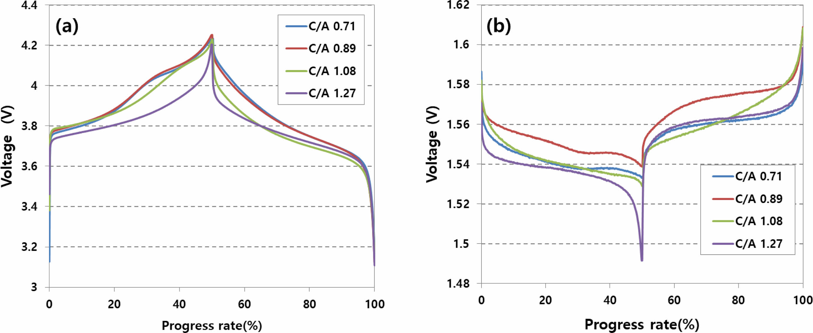
Figure 1 depicts the results of analyzing the potential behavior of the anode and cathode during the charging/discharging of an LTO battery designed based on the anode/cathode loading ratio through a three-electrode experiment. In the case of the anode, with an increasing anode/cathode loading ratio, the reference potential decreases from 4.25 V to 4.20 V. Simultaneously, for the cathode, there is a tendency for the potential to decrease from 1.55 V to 1.50 V.
When the anode capacity surpasses the cathode capacity, the cathode reaction concludes more quickly than the anode, causing the potential to drop below the reaction potential with Li ions. As the cathode potential decreases, the anode potential also decreases, aligning to maintain the same operating voltage of 2.7 V.
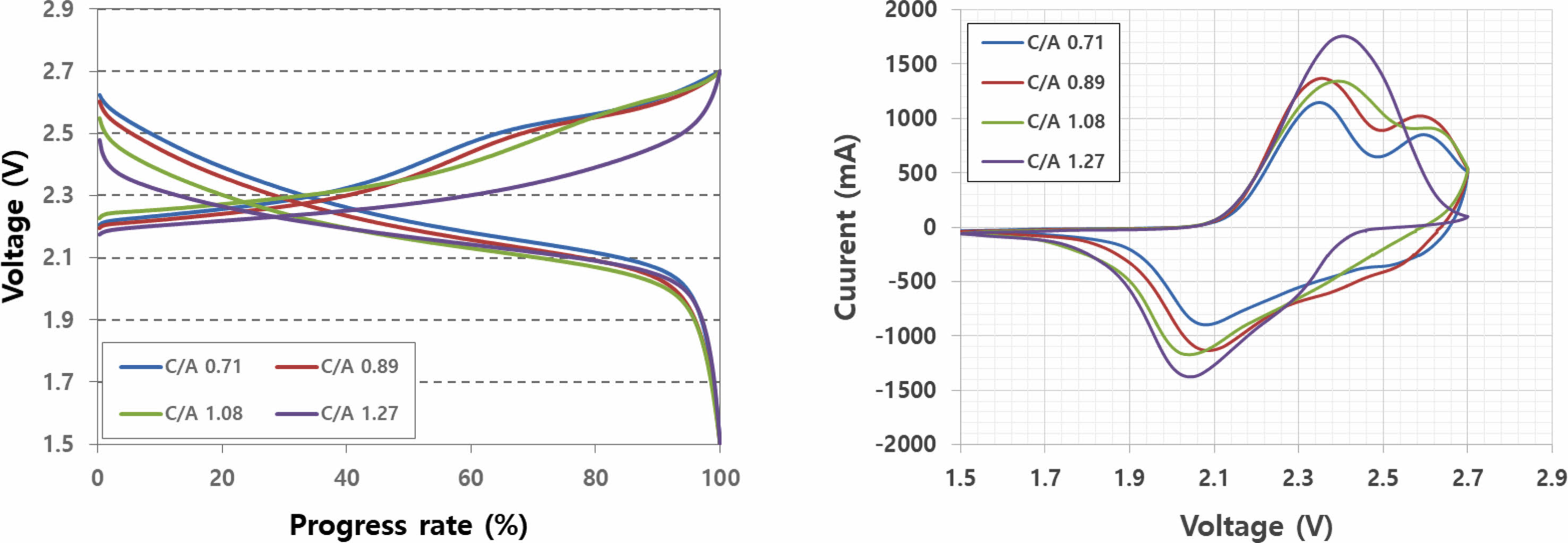
Figure 2 illustrates charge/discharge and cyclic voltammetry (CV) curves based on the anode/cathode loading ratio. In the CV curve, the reaction area of NCNM and LCO was observable within the anode/cathode loading ratio range of 0.71-1.08. However, at an anode/cathode loading ratio of 1.27, only the reaction area of NCM was evident. When the anode capacity exceeds the cathode capacity, the reaction area of LCO does not appear due to the completion of the LTO reaction before LCO reacts, given its higher reaction voltage. This is evident in the charge/discharge curve at an anode/cathode ratio of 1.27, where the slope decreases because LCO remains unreactive.
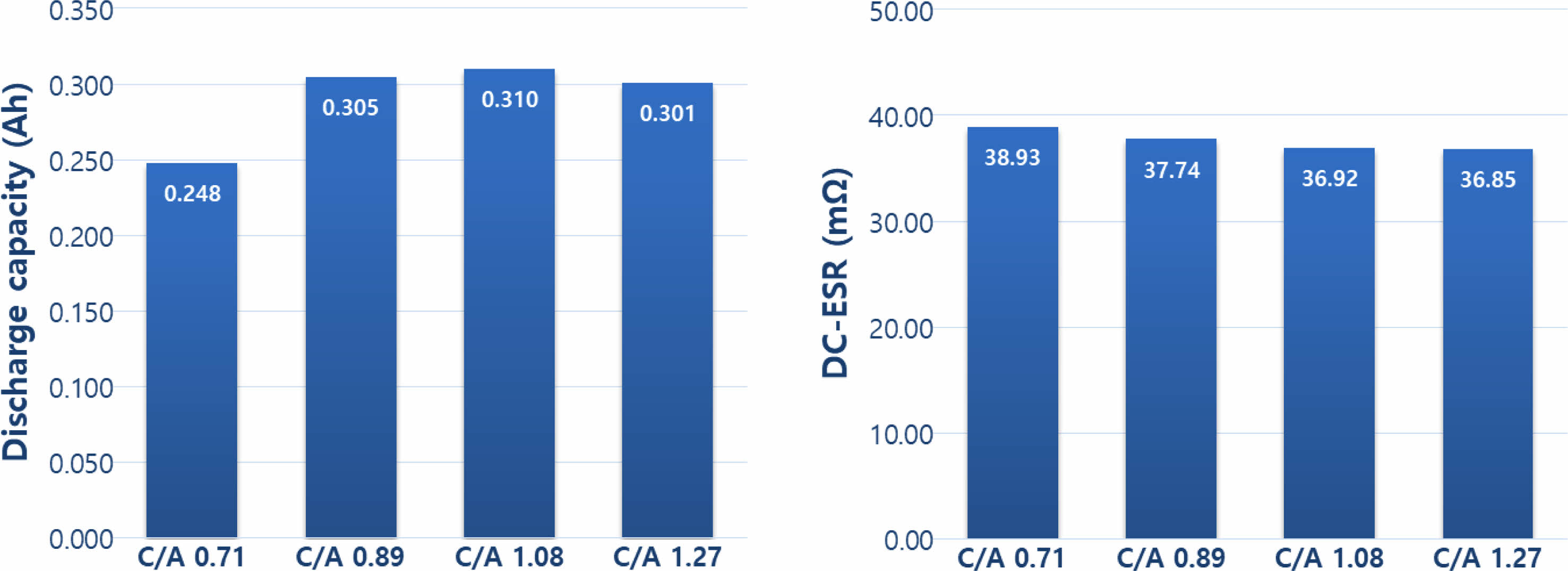
Moving to Fig. 3, it displays the results of capacity and DC-ESR characteristics based on the anode/anode loading ratio. The capacity exhibited an increase as the anode/cathode loading ratio increased up to 1.08 but decreased at a loading ratio of 1.27. This outcome suggests that an excessively high anode loading compared to the cathode loading leads to increased electrode thickness. Consequently, the physical reaction distance of Li ions from the anode increases, impairing the proper implementation of anode capacity and causing a decrease in overall capacity. The DC-ESR characteristics, on the other hand, tend to decrease with an increasing anode/cathode loading ratio. A smaller ESR translates to reduced heat generation during use, offering the advantage of extending the lifespan of the cell.
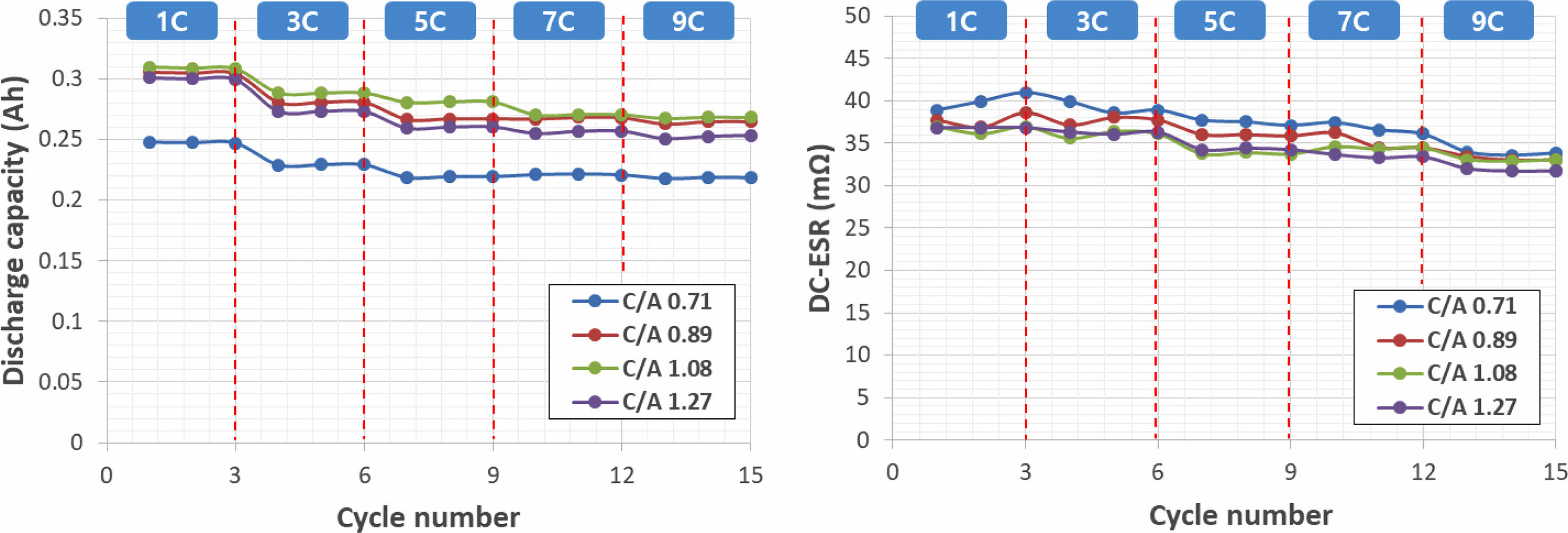
Figure 4 depicts capacity and DC-ESR in relation to anode/cathode loading ratio and current density. It is evident that both capacity and DC-ESR decrease with an increase in current density. To achieve the high output characteristics that are advantageous for LTO batteries, it is imperative that the capacity and ESR change rate remain small with varying current density. Interestingly, as the anode/cathode loading ratio increases, there is a tendency for high output characteristics to decrease.
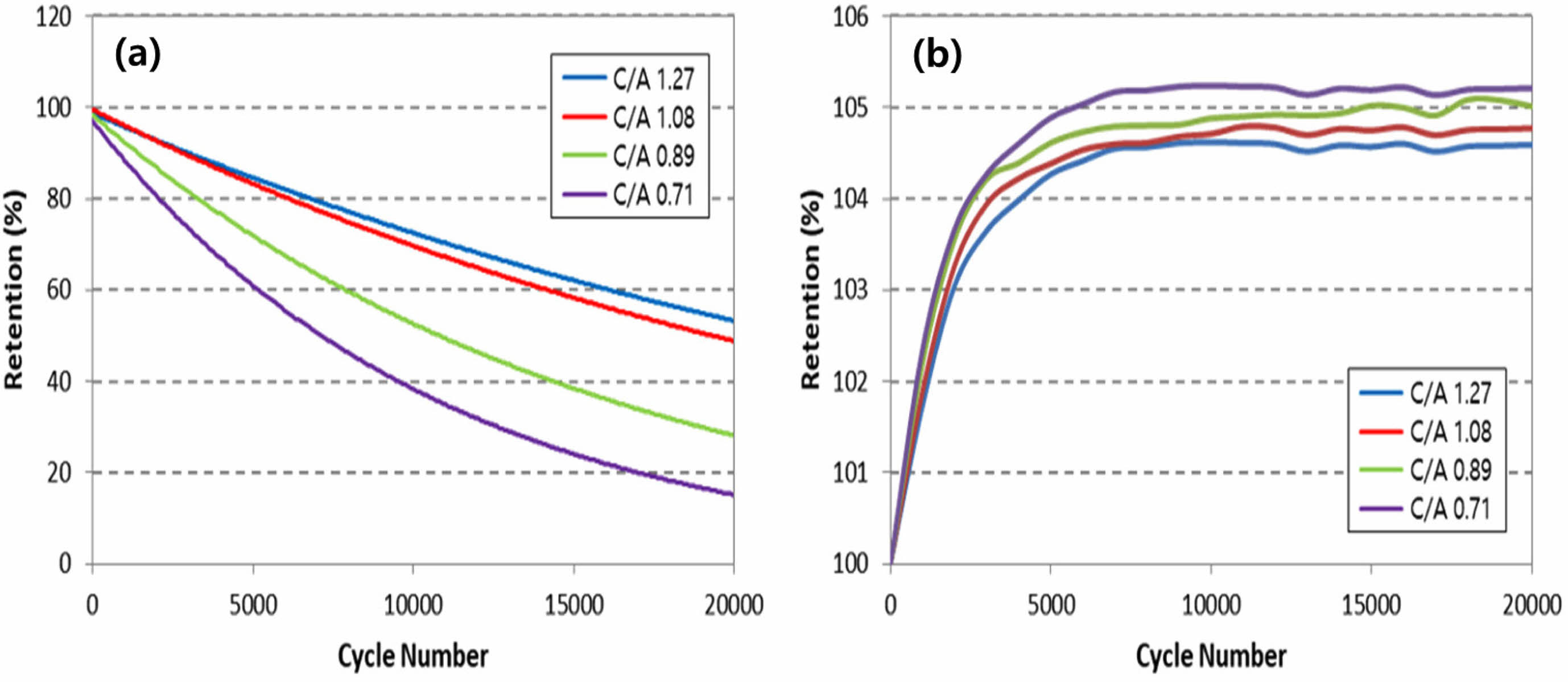
Figure 5 illustrates the lifespan characteristics based on the anode/cathode loading ratio, with evaluations conducted at 60°C and a current of 10C. Notably, it becomes apparent that the larger the anode/cathode loading ratio, the better the observed lifespan characteristics. This observation is consistent with the fact that positive electrode active materials such as NCM and LCO undergo a change in the volume of their crystal structure during the charge/discharge process, whereas LTO, serving as a negative electrode active material, does not experience such volume changes [11].
Given this characteristic, the deterioration of positive electrode active materials progresses faster than that of the negative electrode active material during identical charge/discharge processes. Consequently, achieving a balance in the lifespan between the active materials requires designing the loading density of the positive electrode active material to be larger than that of the negative electrode active material. As a result, the lifespan characteristics of the LTO battery are improved.
|
Fig. 1 Analysis of charge/discharge characteristics using three-electrode analysis method. (a) cathode pontential, (b) anode potential. |
|
Fig. 2 Charge/discharge and cyclic voltammetry characteristics according to cathode/anode loading ratio. |
|
Fig. 3 Capacity and Dc-ESR characteristics according to cathode/anode loading ratio. |
|
Fig. 4 Capacity and DC-ESR characteristics according to cathode/anode loading ratio and current density. |
|
Fig. 5 High temperature lifespan characteristics according to anode/cathode loading ratio. (a) discharge capacity retention, (b) internal resistance retention. |
For the optimal design of the LTO battery, manufacturing was carried out according to the loading ratio of the anode and cathode. Typically, in lithium secondary batteries employing graphite as a negative electrode active material, lithium plating can occur when the negative electrode loading density is designed to be lower than that of the positive electrode. This phenomenon leads to the formation of dendrites, resulting in short circuits. In contrast, as dendrites do not form in LTO batteries, the anode loading density can be designed to be larger than that of the cathode. It was confirmed that the characteristics of cases where the anode loading density was designed to be larger than the cathode were relatively superior compared to the reverse case.
Through a comprehensive assessment of capacity, resistance, energy, output, and lifespan characteristics, it was determined that the LTO battery with an anode/cathode loading ratio of 1.08 exhibited the best performance.
This work was supported by the Technology Innovation Program (10062226, The development of battery capacitor (58Wh/L) composed of graphene and lithium transition metal oxide based flexible electrode for IoT device) funded By the Ministry of Trade, Industry & Energy (MOTIE, Korea).
- 1. B.V. Babu, M.S. Reddi, A.R. Krishna, et al. Structural, Impedance and Modulus Studies of Effect of Magnesium (Mg) Substitution on Spinel Li4Ti5O12 Anode Materials. Trans. Electr. Electron. Mater. 23 (2022) 499-508.
-

- 2. S.-W. Cho, J.-H. Ju, S.-H. Ryu, and K.-S. Ryu, J. Korean Electrochem. Soc. 13 (2010) 264-269.
-
- 3. S.-M. Kim, B.-S. Jin, G.-J. Park, and H.-S. Kim, J. Electrochem. Sci. Technol. 5 (2014) 87-93.
-
- 4. H.-J. Noh, S. Youn, C.S. Yoon, Y.-K. Sun, J. Power Sources 233 (2013) 121-130.
-
- 5. J. Cho, Y.J. Kim, and B. Park, Chem. Mater. 12 (2000) 3788-3791.
-
- 6. Y.-H. Chang and S.-Y. Choi, J. Korean Electrochem. Soc. 10 (2007) 184-189.
-
- 7. S.H. Ju, I.-S. Kang, Y.-S. Lee, W.-K. Shin, S. Kim, K. Shin, and D.-W. Kim, ACS Appl. Mater. Interfaces 6 (2014) 2546-2552.
-
- 8. W. Cho, S.-M. Kim, J. H. Song, T. Yim, S.-G. Woo, K.-W. Lee, J.-S. Kim, and Y.-J. Kim, J. Power Sources 282 (2015) 45-50.
-
- 9. Y. Chen, Y. Zhang, B. Chen, Z. Wang, and C. Lu, J. Power Sources 256 (2014) 20-27.
-
- 10. J.W. Seok, J. Lee, T. Rodgers, D.H. Ko, J.H. Shim, Trans. Electr. Electron. Mater. 20 (2019) 548-553.
-
- 11. R. Koerver, W. Zhang, L. Biasi, S. Schweidler, A. Kondrakov, S. Kolling, T. Brezesinski, P. Hartmann, W. G. Zeier, and J. Janek, Energy Environ. Sci. 11 (2018) 2142-2158.
-
 This Article
-
2024; 25(4): 613-616
Published on Aug 31, 2024
- 10.36410/jcpr.2024.25.4.613
- Received on Mar 28, 2024
- Revised on Jun 11, 2024
- Accepted on Jun 12, 2024
Services
- Abstract
introduction
experimental
results and discussion
conclusions
- Acknowledgements
- References
- Full Text PDF
Shared
Correspondence to
- Jung-Rag Yoon
-
R&D Center, SAMWHA CAPACITOR, Yongin, South Korea
Tel : +82-31-330-5765 Fax: +82-31-332-7661 - E-mail: yoonjungrag@samwha.com
Clean-Energy Research Institute(CRI), Hanyang University, 222, Wangsimni-ro, Seongdong-gu, Seoul, 04763, Korea
E-mail: jcpr@hanyang.ac.kr