- Micropore controlled ceramic filter with mullite whiskers for filtering non-exhaust particulate matter from road transport
Seung-Hwa Oha,b, Jong-Han Choia, Jung-Hun Choia, Kwang-Taek Hwanga, Jin-Ho Kima, Taeseup Songb and Kyu-Sung Hana,*
aIcheon Branch, Korea Institute of Ceramic Engineering and Technology, Icheon 17303, Republic of Korea
bDepartment of Energy Engineering, Hanyang University, Seoul 04763, Republic of KoreaThis article is an open access article distributed under the terms of the Creative Commons Attribution Non-Commercial License (http://creativecommons.org/licenses/by-nc/4.0) which permits unrestricted non-commercial use, distribution, and reproduction in any medium, provided the original work is properly cited.
The transportation sector is high contributor of atmospheric particulate matter (PM). PM from this sector is classified as exhaust and non-exhaust PM. The development of catalytic filters such as diesel particulate filters and eco-friendly automobiles such as electric vehicles has significantly reduced exhaust PM generation. By contrast, non-exhaust PM from various sources such as brake disk abrasion, tire wear, and road dust rediffusion continues to rise owing to the increasing demand for vehicles. The increasing levels of PM and various air pollutants have increased the need for effective filters. This study investigated the manufacturing process and filtering performance of porous ceramic filters for reducing non-exhaust PM generated from road transport. Porous ceramic filters with mullite whiskers were fabricated through the replica template method, using MoO3 as the catalyst. Pore size of ceramic filter was controlled to improve the filtering performance. The applicability of the ceramic filter for filtering non-exhaust PM from road transport was also examined by measuring the pressure drop. The fabricated porous ceramic filter exhibited high filtering performances of 82% for PM2.5 and 97% for PM10. Pressure drop of ceramic filter was 80 Pa when pores of different sizes were optimized.
Keywords: Ceramic filter, Mullite whisker, Non-exhaust particulate matter, Porous structure.
Particulate matter (PM) is a harmful substance that causes various diseases when aspirated into the human lungs and bronchial tubes. PM is classified into PM2.5 and PM10 according to the particle diameter in microns. PM sources include automotive fuel combustion, brake pad wear, tire wear for the transportation sector and combustion in factories for the industrial sector [1, 2]. The transportation sector is the largest PM source, and PM from this sector is classified into exhaust and non-exhaust PM [3]. Exhaust PM generation has been gradually reduced by the development of catalytic filters and eco-friendly automobiles. However, non-exhaust PM generation such as those from brake disk abrasion, tire wear, and road dust rediffusion continues to increase with the demand for vehicles [4-8].
Pressure drop performance is critical to filters for non-exhaust PM emission. When the pressure drop increases during the filtration process, PM flows to the outside and cannot be trapped in the filter. Thus, low pressure drop needs to be maintained for non-exhaust PM filtering [9, 10]. In addition, the brake disk where filters are installed produces high temperatures above 700°C owing to friction and metal particles generated from brake pads, reducing the filter durability [11]. Therefore, non-exhaust PM filters require low pressure drop, high-temperature durability, chemical resistance, and sufficient mechanical strength [12]. Porous ceramics can secure low pressure drop performance with high porosity. They also have high heat and chemical resistances owing to the unique characteristics of ceramic materials [13, 14]. Among various manufacturing methods for porous ceramics, the replica template method has been widely used because it can suitably control porosity and pore geometry of porous ceramics compared with other manufacturing methods [15-17]. The replica template method involves coating ceramic slurry on a porous template and implementing a heat treatment process to manufacture porous ceramics in the shape of the template [18]. The pore characteristics of the ceramic filter after the sintering process can be adjusted by controlling the pore characteristics of the porous template. The replica template method can also produce porous ceramics with open-pore structures connected in the shape of a net. However, porous ceramics manufactured using the replica template method exhibit lower strength than those manufactured using other methods because the removal of the template after sintering forms hollow struts and cracks owing to the contraction that occurs during the sintering process [19, 20]. Therefore, previous research was conducted to improve low mechanical properties by growing SiC and mullite whiskers such inside the pores of the ceramic filter manufactured through the replica template method [21-24].
Mullite whiskers are the stable aluminosilicate crystals produced in the solid reaction between Al2O3 and SiO2 and are more stable than other whiskers [25-28]. Mullite has high mechanical strength, high creep resistance, and low coefficient of thermal expansion. It can be produced using inexpensive raw materials, such as kyanite, kaolin, and fly ash [29-33]. Mullite whisker growth can be accelerated by lowering the mullitization temperature using AlF3, WO3, V2O5, MgO, La2O3, and TiO2 as catalysts [34-39]. Among these catalysts, porous ceramics with mullite whiskers are reported to have high mechanical strength and porosity with MoO3 catalyst. Hou et al. reported that porous ceramics with mullite whiskers, which synthesized using MoO3 as a catalyst, showed high porosity compared owing to low mullitization temperature [40]. Shin et al. fabricated porous ceramic filters with mullite whiskers and examined PM filtering performance and mechanical strength. The filters exhibited high filtering performance for PM10 and relatively low filtering performance for PM2.5 [41].
In this study, PM filtering efficiency and mechanical properties of porous ceramic filters were investigated with controlling pore characteristics. Mullite whiskers were grown inside the pores of the ceramic filter to improve the overall filtering efficiency and mechanical strength. In addition, the ceramic filter was fabricated by combining templates with different pore characteristics to decrease the pressure drop and improve filtration performance of PM 2.5 for evaluation its potential as non-exhaust PM filter was examined.
Raw materials
Kaolin (Samchun Chemicals, d50:14.7 µm) and Al2O3 (Sumitomo Chemicals, d50: 0.34 µm) were used as raw materials for fabricating porous ceramic filters. Glass frit (Shinceramic, d50: 0.25 µm) was used to improve mechanical strength of the filter. Table 1 shows the chemical compositions of the kaolin and glass frit. In addition, MoO3 (Sigma-Aldrich, d50: 14.4 µm) was used as a catalyst to decrease the mullitization temperature and accelerate whisker growth.
Sample preparation
Polyurethane foams with various pore characteristics of 60, 80, and 100 pores per inch (PPI) were used as templates to fabricate the porous ceramic filters. PPI indicates the cell density of foam. The average cell size ranged from 300 μm to 600 μm for 60 PPI foam, 200 μm to 300 μm for 80 PPI foam, and 100 μm to 200 μm for 110 PPI foam. Microscopic images of polyurethane foams with various pore size were shown in Fig. 1.
The slurry for coating polyurethane foam was prepared by mixing 720 g of deionized (DI) water as a solvent with 80 g of polyvinyl alcohol (PVA, Sigma-Aldrich, Mw: 9,000-10,000) as a binder. 60 g of Al2O3, 30 g of kaolin, 10 g of frit, and 20 g of MoO3 were added in PVA contained solution. Then, ceramic coating slurry was mixed through ball milling for 18 h. After impregnating polyurethane foam in the coating slurry, the squeezing was proceeded with a roller to improve uniformity of the coating layer. Drying was carried out for 1 h in an oven at 75°C. The dried green body was placed in an alumina crucible and sintered for 3 h at 1,300°C in an electric furnace. To prevent cracking in the ceramic filter during the sintering process, the temperature was increased from room temperature to 550°C at 1°C/min rate and maintained for 1 h. Subsequently, the temperature was increased from 550°C to 900°C at 3°C/min rate and maintained for 1 h. The temperature was then increased from 900°C to the final sintering temperature at 5°C/min rate and maintained for 3 h. All the ceramic filters were prepared with 3 mm thickness. In case of the ceramic filters prepared by combining two different PPI templates, the ceramic filters were polished to obtain 1.5 mm thickness for each layer.
Characterization
The composition of raw materials for ceramic filter fabrication was analyzed using an inductively coupled plasma atomic emission spectroscopy (ICP-AES, OPTIMA 5300 DV, PerkinElmer). The viscosity of the coating slurry was measured using a cup and hole type rheometer (HAAKE MARS III, Thermo Fisher Scientific Inc.). The crystal structure of the ceramic filter was analyzed through X-ray diffraction (XRD, D/2500VL/PC, Rigaku), and the microstructure was observed through scanning electron microscopy (SEM, JSM-6390, JEOL). The pore characteristic was analyzed through mercury intrusion porosimetry (Autopore V, Micromeritics), and the compressive strength was measured using the modulus of rupture (Inspekt 250, Metesco). The filtering efficiency of the ceramic filter was evaluated using Arizona standard test dust (ISO 12103-1 A1 Ultrafine test dust). Arizona standard test dust was dried for 24 h to remove moisture before the filtering efficiency evaluation.

|
Fig. 1 Microscopic images of polyurethane foams with various pore size. (a) 60 PPI, (b) 80 PPI, (c) 110 PPI |
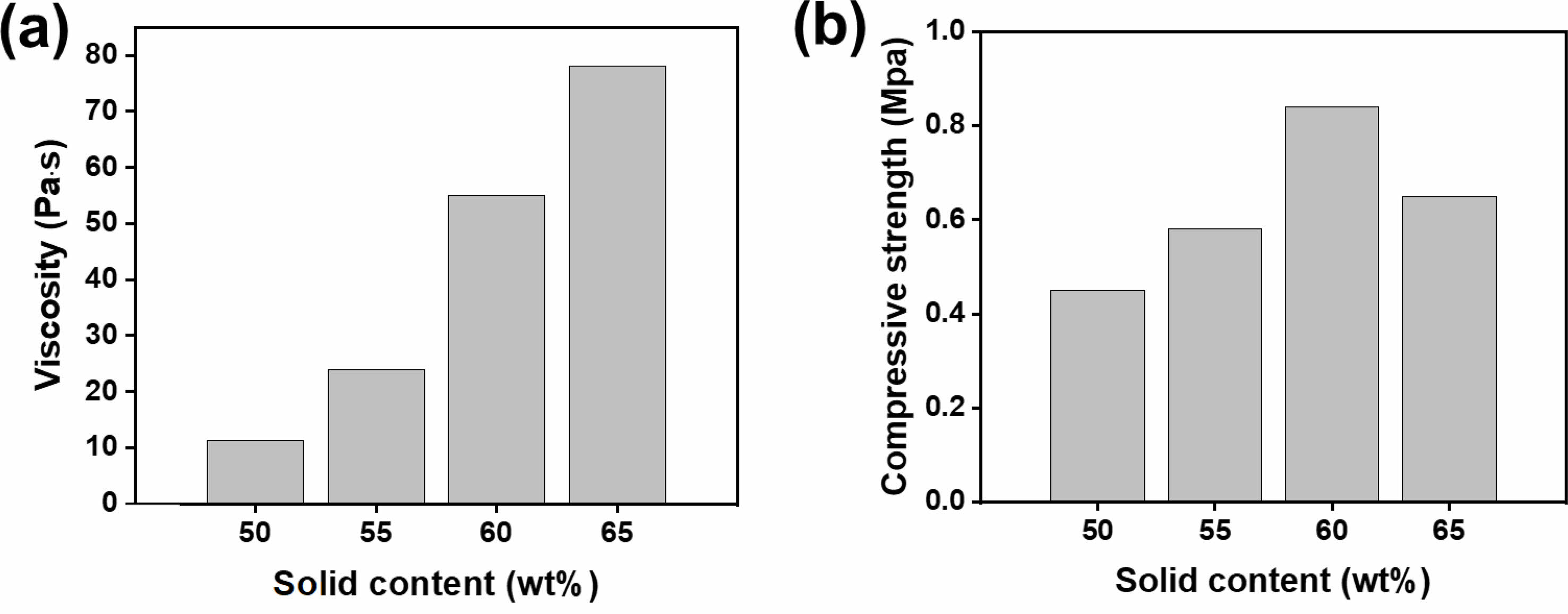
The viscosity of the coating slurry is the most important variable for fabricating porous ceramic filters with a uniform structure using the replica template method. When the viscosity is too high, the ceramic slurry cannot be coated inside the template due to insufficient fluidity. In contrast, the low viscosity of the ceramic slurry results in insufficiently coating on the template, and the porous structure may not be maintained during heat treatment. Fig. 2(a) shows the viscosity measurement results of the coating slurry used to fabricate the porous ceramic filters. The viscosity of the slurry was examined by adjusting the solid content from 50 wt% to 65 wt% to find the optimal conditions for the template coating. The coating slurry contained 50-55 wt% solid content exhibited relatively low viscosity values of 11.3-24 Pa·s. The viscosity of the slurry significantly increased significantly when the solid content was 55 wt% or higher. When the solid contents of the coating slurry increased to 60 wt% and 65 wt%, viscosity values were 55.1 Pa·s and 78.1 Pa·s, respectively. Fig. 2(b) shows compressive strength of the porous ceramic filter sintered at 1,300°C after coating the template with the slurry. Mechanical property of the fabricated ceramic filter was examined for preventing damage when mounted on automotive brake pads. The ceramic filter fabricated using the coating slurry with 50 wt% solid content exhibited compressive strength of 0.45 MPa. Compressive strength of the ceramic filter increased to 0.58 MPa and 0.84 MPa, when the solid content increased to 55 wt% and 60 wt%, respectively. However, compressive strength decreased to 0.65 MPa, when the solid content was increased to 65 wt%. Degradation of compressive strength at high solid content is mainly due to excessively high viscosity of the slurry and reduced fluidity. Coating was not efficiently performed inside the template, causing the incomplete formation of internal struts after the sintering process. Consequently, the solid content of the coating slurry could be optimized as 60 wt%, which showed the compressive strength, for the ceramic filter fabrication.
Fig. 3 shows XRD patterns measured to identify the crystal structure of the porous ceramic filter fabricated using the template with various pore size. The solid content in the coating slurry was adjusted between 50 and 60 wt%, and the sintering process of the ceramic filter was performed at 1,300°C. In XRD analysis results, the fabricated ceramic filters showed a single phase of mullite regardless of the solid content in the coating slurry and the pore size of template. During the heat treatment, MoO3 catalyst forms Al2(MoO4) 3 by reacting with Al2O3 at approximately 500°C. Then, Al2(MoO4)3 is decomposed into Al2O3 and 3MoO3 at approximately 800°C. The decomposed Al2O3 accelerates dissolution–precipitation reaction more significantly than Al2O3 of the staring material. The acceleration of Al2O3 dissolution in SiO2 reduces the mullitization temperature [32]. In addition, mullite particles that rapidly grow along the c-axis are grown in the form of anisotropic whiskers by MoO3.
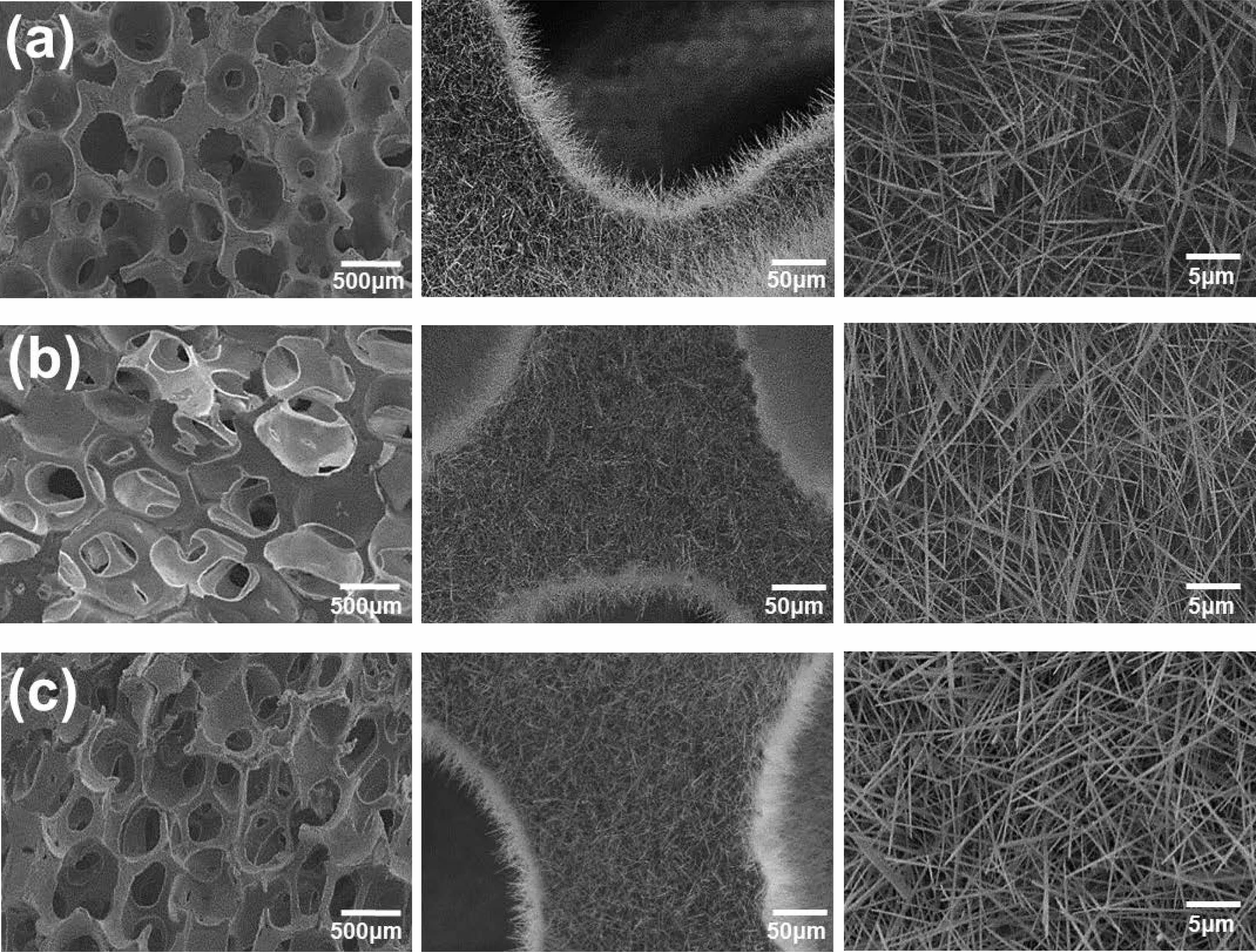
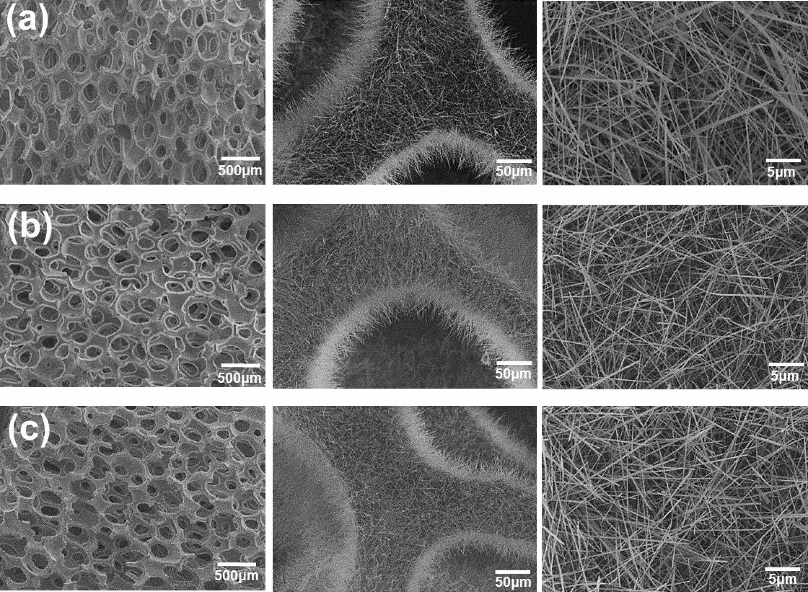
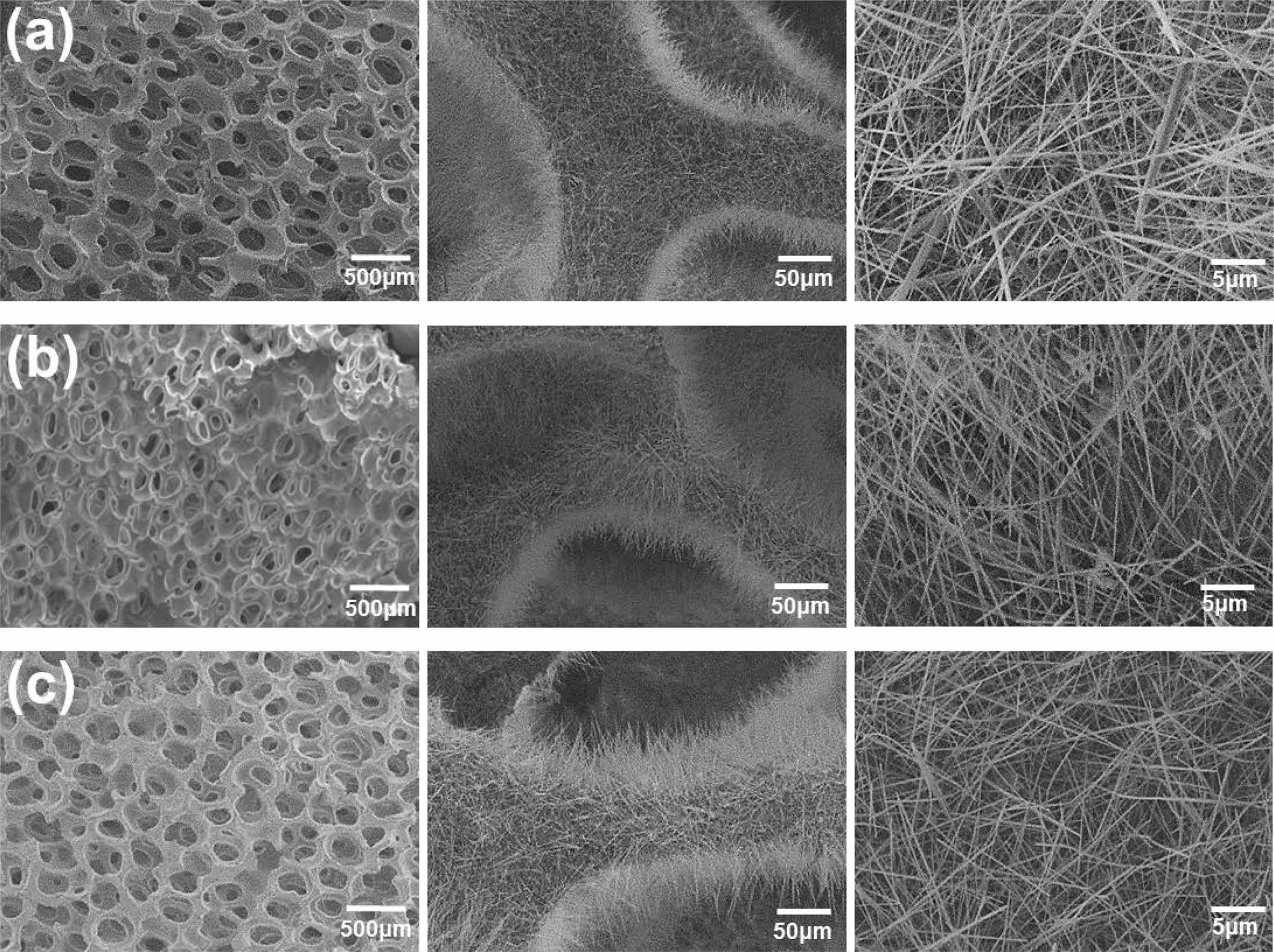
Fig. 4 shows the microstructure of the ceramic filter prepared using 60 PPI template. The solid content in the coating slurry was adjusted between 50 and 60 wt%, and the sintering process of the ceramic filter was performed at 1,300°C. The overall pore structure of the filter could be observed from SEM images, and the growth of needle-shaped mullite whiskers on the strut surface was observed. The number of mullite whiskers increased with the solid content in the coating slurry. This may be due to the increased amount of alumina, which is the seed for the mullite whisker growth. Fig. 5 and 6 show the microstructures of the ceramic filters fabricated using the templates with 80 and 110 PPI, respectively. The pore characteristics of the filter prepared using the replica template method varied according to PPI of the template. The number of cells that form pores increased and the pore size decreased in the same area as PPI of template increased. For 110 PPI ceramic filter shown in Fig. 6, the number of struts that form the filter structure increased compared with those shown in Fig. 4 and 5. Consequently, the mullite whiskers formed on the struts also exhibited a denser microstructure.
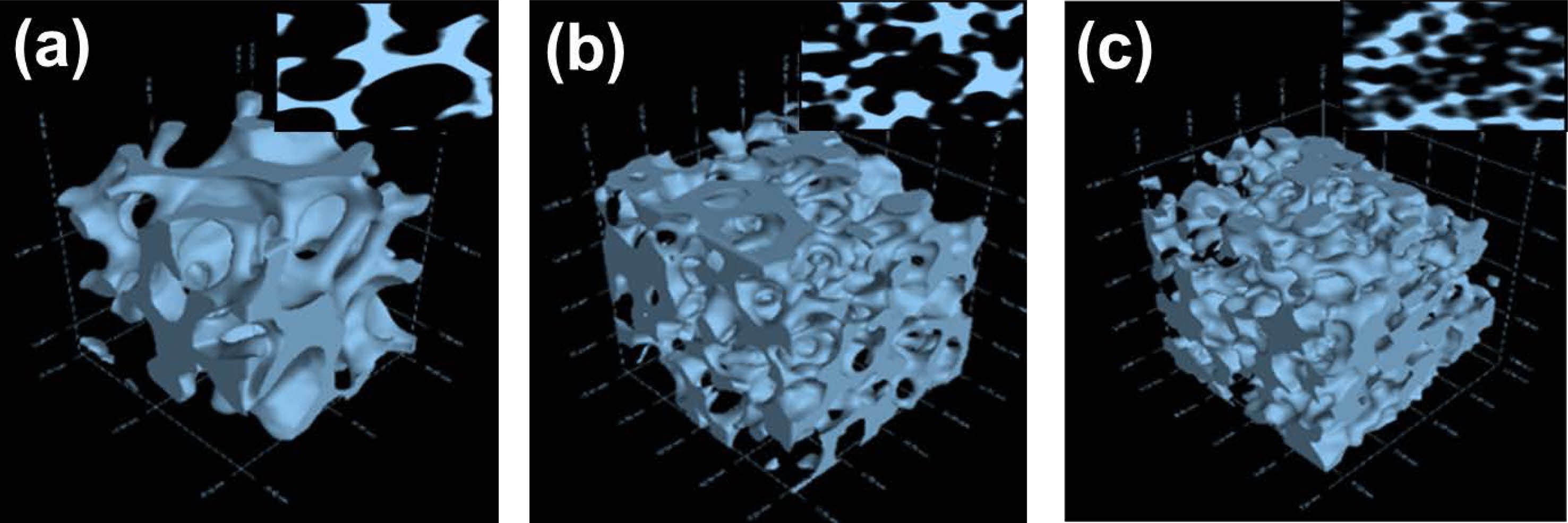
Micro computed tomography (micro CT) was measured to observe the internal pore characteristics of the ceramic filters prepared using the templates with different PPI values in more detail. Fig. 7 shows the three dimensional (3D) micro CT images of the ceramic filters prepared using the coating slurry with 60 wt% solid content, which showed the most efficient coating. As confirmed by SEM analysis results, more struts and pores were observed in the same area, and the internal pore size decreased as the PPI of the template increased. Struts that form the internal pore structure of the filter have 3D network structure. Thus, the mullite whiskers in the filter are expected to improve filtering efficiency when PM is filtered between the pores.
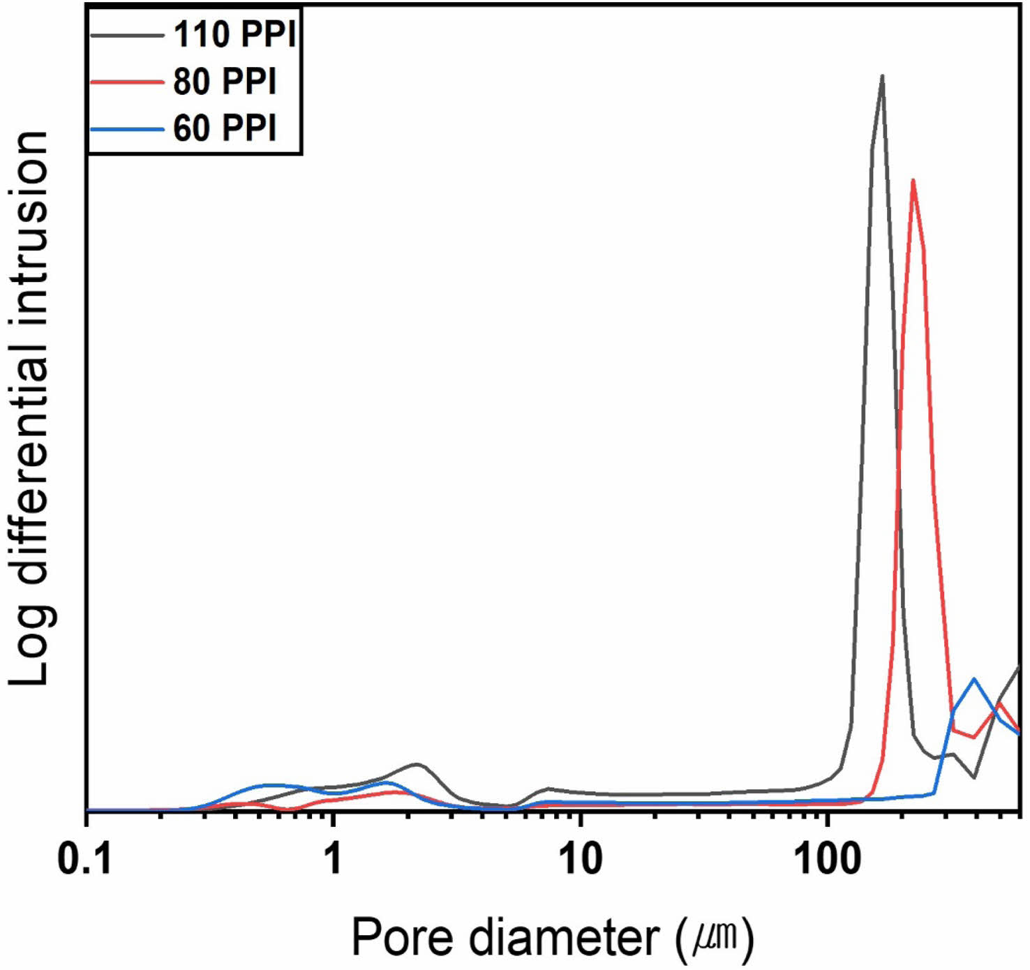
Fig. 8 shows the pore size distribution of the ceramic filters fabricated using the templates with various PPI values. The filters were prepared using the coating slurry with 60 wt% solid content, and sintering was performed at 1,300°C. The porosity of the ceramic filters increased from 83% to 86% as the pore characteristics of the template increased from 60 PPI to 110 PPI, whereas the average pore size decreased from 334 μm to 160 μm. The analysis results of porosity and pore size were consistent with the microstructure analysis results using SEM and micro CT. The pore size distribution indicated that the ceramic filter included 100-400 μm sized pores, which were measured from the porous ceramic matrix, and 0.2-3 μm sized pores, which were judged to be micropores among the mullite whiskers grown from the struts.
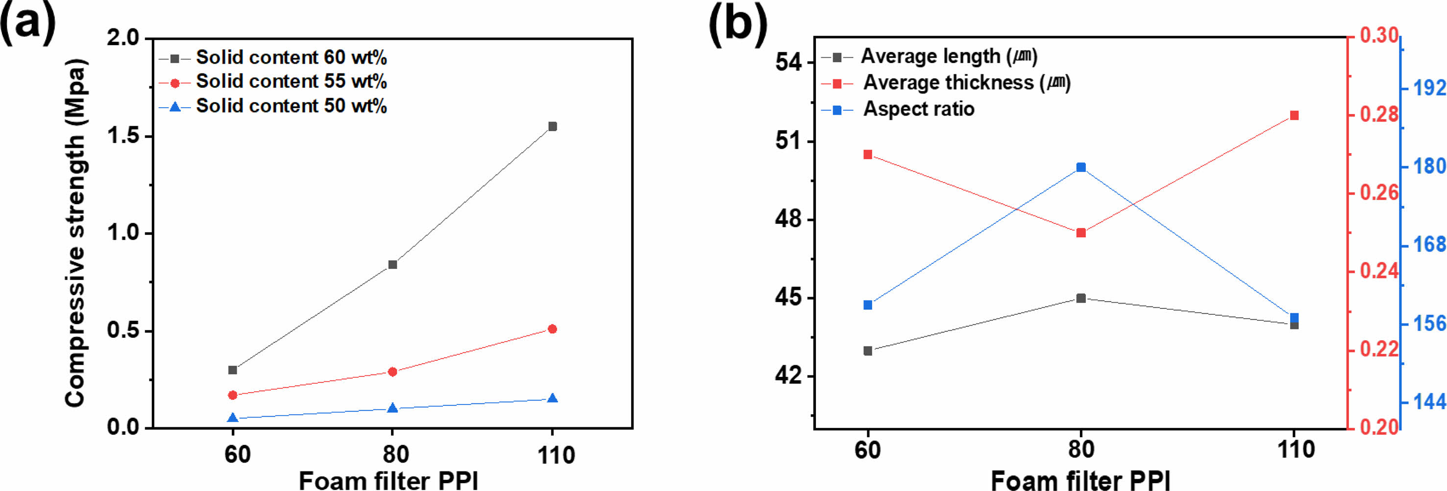
Fig. 9 displays the analysis results of the mechanical property of the ceramic filters and geometry of the mullite whiskers according to the pore characteristics of the templates and solid content in the coating slurry. Fig. 9(a) shows the compressive strength of the ceramic filters fabricated under various conditions. The compressive strength of the ceramic filters increased with PPI of the template. This tendency was more significant as the solid content in the coating slurry increased. The compressive strength increased from 0.05 MPa to 0.15 MPa, when the solid content was 50 wt%. The compressive strength increased from 0.17 MPa to 0.51 MPa at 55 wt% solid content and from 0.3 MPa to 1.55 MPa at 60 wt% solid content. The analysis of the mechanical properties of the ceramic filters with mullite whiskers and different pore characteristics revealed that the compressive strength generally increased with the solid content in the coating slurry and PPI of the template. Increased solid content resulted in more whisker growth owing to the increased amount of alumina, which is the seed for the mullite whisker growth, and an increased PPI of the template increased the struts, which are mullite whisker growth sites. The dense mullite whiskers on the strut overlapped to form bridges among the mullite whiskers, resulting in the improved compressive strength.
Fig. 9(b) shows the aspect ratio of the mullite whiskers fabricated using the coating slurry with a 60 wt% solid content. Because mullite whiskers serve as bridges, the effect of the aspect ratio to the mechanical properties of porous filter was investigated. The compressive strength of the ceramic filters increased with PPI of the template, as shown in Fig. 9(a). By contrast, there was no significant difference in the aspect ratio of the mullite whiskers. The aspect ratio of the mullite whiskers were 159, 180, and 157, when the ceramic filters were fabricated using 60, 80, and 110 PPI templates, respectively. This indicates that the aspect ratio did not significantly influence the compressive strength of the ceramic filters. However, the aspect ratios of the ceramic filters prepared in this study were much higher than those of the mullite whiskers obtained using the MoO3 catalyst in a previous study [41]. Consequently, the fabricated filters exhibited higher mechanical properties than existing ceramic filters manufactured using the replica template method. The high aspect ratio of the mullite whiskers can be attributed to the large space caused by the connected pore structure in the ceramic filter.
Fig. 10(a) shows the filtering performance of the ceramic filters with mullite whiskers and different pore size. The average filtering efficiency for ultrafine dust sized between 0.3 μm and 2.5 μm increased from 46% to 63 and 78.4%, as PPI increased from 60 PPI to 80 and 110 PPI. The struts and mullite whiskers in the ceramic filters became denser and had favorable shapes for collecting PM, as PPI of the template increased. However, the increased struts in the ceramic filter reduced the pore size and affected the pressure drop. The pressure drop for the filters with different pore size in Fig. 10(b) increased from 21 Pa to 49 and 310 Pa, as PPI of the template increased from 60 to 80 and 110, respectively. The ceramic filter prepared using the 110 PPI template demonstrated high filtering performance for ultrafine dust. However, the pressure drop rapidly increased. Therefore, the pore structure should be improved such that the pressure drop does not exceed 300 Pa, which is the requirement for non-exhaust PM filter application.
In order to reduce the pressure drop while maintaining the filtering efficiency of the ceramic filter for ultrafine dust, ceramic filters with two pore sizes were fabricated by combining templates with different PPI values. The pore structure was improved by combining the ceramic filters prepared using the 60 and 80 PPI templates with 110 PPI template, which had the highest filtering performance for ultrafine dust and pressure drop unsuitable as a non-exhaust PM filter. Fig. 11(a) shows the templates with different PPI values bonded using polymer spray. Ceramic filters were fabricated using the ceramic coating slurry with 60 wt% solid content. Fig. 11(b) shows the image of the ceramic filter with two pore sizes after heat treatment. Fig. 11(c) shows the cross-sectional microstructure of the ceramic filter for the part where the pore size changed. The images indicate that the porous structure with two pore characteristics was well maintained even after heat treatment, thus different pore structures were successfully combined.
Fig. 12 shows the filtering performances and pressure drop of the ceramic filters with two pore sizes. Fig. 12(a) shows the filtering efficiency for the ceramic filters prepared by combining 60 and 80 PPI templates with 110 PPI template. Evenly high filtering efficiency was obtained for 0.3 μm to 2.5 μm sized ultrafine dust and 2.5 μm to 10 μm sized PM. This may be due to the pore structure of the ceramic filter prepared using 110 PPI template. The ceramic filter fabricated by combining the 60 and 110 PPI templates exhibited average ultrafine dust and PM filtering efficiencies of approximately 82% and 97%, respectively. When 80 and 110 PPI templates were combined, the ceramic filter exhibited average ultrafine dust and PM filtering efficiencies of approximately 86% and 97%, respectively. Both ceramic filters with two pore sizes showed similar filtering efficiency for PM, and the ceramic filter with the combined 80 and 110 PPI templates exhibited slightly higher filtering efficiency for ultrafine dust. Fig. 12(b) shows the pressure drop measurement results according to the filtering time for the ceramic filters with two pore sizes. The initial pressure drop was 120 Pa for the ceramic filter with the combined 80 and 110 PPI templates, However, it rapidly increased with the filtering time and reached 390 Pa after 60 min. This confirmed that the filter is unsuitable for non-exhaust PM filter applications. By contrast, the pressure drop of the ceramic filter with the combined 60 and 110 PPI templates exhibited no significant increase, remaining at 80 Pa after 60 min. This confirmed that the filtration can be further processed. Moreover, this ceramic filter can obtain high PM filtering efficiency in the filter section with 110 PPI while maintaining a low pressure drop suitable for non-exhaust PM filtering using the filter section with 60 PPI.
|
Fig. 2 (a) Viscosity of coating slurry prepared with various solids contents and (b) compressive strength of ceramic filter after sintering process. |

|
Fig. 3 XRD patterns of ceramic filter prepared with (a) 60 PPI, (b) 80 PPI, (c) 110 PPI template. |
|
Fig. 4 SEM images of ceramic filter with mullite whiskers prepared using 60 PPI template and coating solution of (a) 50 wt%, (b) 55 wt%, (c) 60 wt% solid contents. |
|
Fig. 5 SEM images of ceramic filter with mullite whiskers prepared using 80 PPI template and coating solution of (a) 50 wt%, (b) 55 wt%, (c) 60 wt% solid contents. |
|
Fig. 6 SEM images of ceramic filter with mullite whiskers prepared using 110 PPI template and coating solution of (a) 50 wt%, (b) 55 wt%, (c) 60 wt% solid contents. |
|
Fig. 7 Micro CT images of ceramic filters prepared with (a) 60 PPI, (b) 80 PPI, (c) 110 PPI template. |
|
Fig. 8 Pore size distribution of ceramic filters with mullite whiskers. |
|
Fig. 9 Effects of pore property on (a) compressive strength of ceramic filter and (b) aspect ratio of mullite whiskers. |

|
Fig. 10 (a) Filtering performance and (b) pressure drop of ceramic filters fabricated using templates with various pore characteristics |

|
Fig. 11 Optical images of (a) polyurethane foam with different PPI and (b) fabricated ceramic filter. (c) Cross sectional SEM image of ceramic filter with dual sized pores. |

|
Fig. 12 (a) Filtering performances and (b) pressure drop of ceramic filters with dual sized pores. |
In this study, ceramic filters with mullite whiskers and various pore characteristics were fabricated, and their properties and filtering performances were investigated in detail. The ceramic filters were fabricated using the replica template method with 60, 80, and 110 PPI templates. Mullite whiskers were grown in the ceramic filters using Al2O3, kaolin, and frit as starting materials to improve the filtering efficiency and mechanical strength. Mullite whiskers were grown at low temperatures using MoO3 as a catalyst. Among the ceramic filters with various conditions such as solid content of coating slurry and pore characteristics of template, the ceramic filter fabricated using 110 PPI template and coating slurry with a 60 wt% solid content exhibited the highest compressive strength of 1.55 MPa and porosity of 86%. The ceramic filters fabricated using the 60, 80, and 110 PPI templates exhibited ultrafine dust filtering efficiencies of 46.3, 63, and 78.4% and pressure drop values of 21, 46, and 310 Pa, respectively. In order to obtain high filtering efficiency and low pressure drop simultaneously, the ceramic filter was fabricated using the combined template with different pore size. The ceramic filter fabricated by combining 60 and 110 PPI templates exhibited high ultrafine dust filtering performance of 82% and a low pressure drop of 80 Pa, confirming the applicability for non-exhaust PM filter.
This work was supported by the Technology Innovation Program (20003782, Development of ceramic filter technology collecting fine dust originated from brake) funded by the Ministry of Trade, Industry & Energy (MOTIE, KOREA), and Ceramic Strategy Technology Development Project (KPP21007) funded by Korea Institute of Ceramic Engineering and Technology.
- 1. Y. Chen, N. Shah, A. Braun, F.E. Huggins, and G.P. Huffman, Energ. Fuel. 19[4] (2005) 1644-1651.
-

- 2. D. Jandacka, D. Durcanska, and M. Bujdos, Transp. Res. D: Transp. Environ. 50 (2017) 397-408.
-

- 3. M. Préndez, M. Araya, C. Criollo, C. Egas, I. Farías, R. Fuentealba, and E. González, in “Urban Climates in Latin America” (Springer, 2019) p.167-206.
- 4. R.M. Harrison, J. Allan, D. Carruthers, M.R. Heal, A.C. Lewis, B. Marner, T. Murrells, and A. Williams, Atmos. Environ. 262[1] (2021) 118592.
-

- 5. V.R.J.H. Timmers and P.A.J. Achten, Atmos. Environ. 134 (2016) 10-17.
-

- 6. N. Hooftman, L. Oliveira, M. Messagie, T. Coosemans, and J.V. Mierlo, Energies. 9[2] (2016) 84.
-

- 7. A. Thorpe and R.M. Harrison, Sci. Total Environ. 400[1-3] (2008) 270-282.
-

- 8. A.S. Nagpure, B.R. Gurjar, V. Kumar, and P. Kumar, Atmos. Environ. 127 (2016) 118-124.
-

- 9. I.S. Hwang and Y.L. Lee, Inter. J. Automot. Techol. 22 (2021) 1257-1265.
-

- 10. I.S. Hwang, J.T. Park, and Y.L. Lee, Inter. J. Automot. Techol. 23 (2022) 521-527.
-

- 11. T. Grigoratos and G. Martini, Environ. Sci. Pollut. Res. 22 (2015) 2491-2504.
-

- 12. I. Nettleship, Key. Eng. Mater. 122 (1996) 305-324.
-

- 13. X. Huai, S. Zhao, and W. Li, J. Ceram. Process. Res. 10[5] (2009) 618-620.
-

- 14. A.E. Pramono, M.Z. Nura, J.W.M. Soedarsono, and N. Indayaningsih, J. Ceram. Process. Res. 20[1] (2019) 1-7.
-

- 15. M. Shibuya, T. Takahashi, and K. Koyama, Compos. Sci. Technol. 67[1] (2007) 119-124.
-

- 16. S. Barg, C. Soltmann, M. Andrade, D. Koch, and G. Grathwohl, J. Am. Ceram. Soc. 91[9] (2008) 2823-2829.
-

- 17. C. Voigt, C.G. Aneziris, and J. Hubálková, J. Am. Ceram. Soc. 98[5] (2015) 1460-1463.
-

- 18. M. Bugdayci and G. Baran, J. Ceram. Process. Res. 22[5] (2021) 510-516.
-

- 19. P. Colombo and E. Bernardo, Compos. Sci. Technol. 63[16] (2003) 2353-2359.
-

- 20. X. He, B. Su, Z. Tang, B. Zhao, X. Wang, G. Yang, H. Qiu, H. Zhang, and J. Yang, J. Porous Mater. 19 (2012) 761-766.
-

- 21. M. Yang, J. Li, Y. Man, Z. Peng, X. Zhang, and X. Luo, J. Asian. Ceram. Soc. 8[2] (2020) 387-395.
-

- 22. C. Li, C. Bian, Y. Han, C.A. Wang, and L. An, J. Eur. Ceram. Soc. 36[3] (2016) 761-765.
-

- 23. Y. Goto and A. Tsuge, J. Am. Ceram. Soc. 76[6] (1993) 1420-1424.
-

- 24. V. Garnier, G. Fantozzi, D. Nguyen, J. Dubois, and G. Thollet, J. Eur. Ceram. Soc. 25[15] (2005) 3485-3493.
-

- 25. L. Zhu, Y. Dong, L. Li, J. Liu, and S.J. You, RSC Adv. 5[15] (2015) 11163-11174.
-

- 26. H. Schneider, J. Schreuer, and B. Hildmann, J. Eur. Ceram. Soc. 28[2] (2008) 329-344.
-

- 27. B.M. Kim, Y.K. Cho, S.Y. Yoon, R. Stevens, and H.C. Park, Ceram. Int. 35[2] (2009) 579-583.
-

- 28. Y.K. Cho, B.M. Kim, S.Y. Yoon, R. Stevens, and H.C. Park, J. Ceram. Process. Res. 9[6] (2008) 652-656.
-

- 29. M.A. Sainz, F.J. Serrano, J. Bastida, and A. Caballero, J. Eur. Ceram. Soc. 17[11] (1997) 1277-1284.
-

- 30. C.Y. Chen, G.S. Lan, and W.H. Tuan, Ceram. Int. 26[7] (2000) 715-720.
-

- 31. Y.M. Park, T.Y. Yang, S.Y. Yoon, R. Stevens, and H.C. Park, Mater. Sci. Eng. A 454-455[25] (2007) 518-522.
-

- 32. T. Boyraz and A. Akkus, J. Ceram. Process. Res. 22[2] (2021) 226-231.
-

- 33. N.T.T. Thao and B.H. Bac, J. Ceram. Process. Res 24[3] (2023) 471-477.
-

- 34. K. Okada and N. Otuska, J. Am. Ceram. Soc. 74 (1991) 2412-2418.
-

- 35. L.B. Kong, H. Huang, T.S. Zhang, J. Ma, F. Boey, R.F. Zhang, and Z.H. Wang, J. Eur. Ceram. Soc. 23[13] (2003) 2257-2264.
-

- 36. N. Montoya, F.J. Serrano, M.M. Reventós, J.M. Amigo, and J. Alarcón, J. Eur. Ceram. Soc. 30[4] (2010) 839-846.
-

- 37. Y. Dong, S. Hampshire, J. Zhou, Z. Ji, J. Wang, and G. Meng, J. Eur. Ceram. Soc. 31[5] (2011) 687-695.
-

- 38. H. Ji, M. Fang, Z. Huang, K. Chen, Y. Xu, Y. Liu, and J. Huang, Ceram. Int. 39[6] (2013) 6841-6846.
-

- 39. J.H. Li, H.W. Ma, and W.H. Huang, J. Hazard. Mater. 166[2-3] (2009) 1535-1539.
-

- 40. Z. Hou, B. Cui, L. Liu, and Q. Liu, Ceram. Int. 42[15] (2016) 17254-17258.
-

- 41. C. Shin, D.K. Lee, S.H. Oh, J.H. Choi, K.T. Hwang, K.S. Han, and J.H. Kim, J. Mat. Res. Technol. 23 (2023) 165-171.
-

- 42. C. Shin, S.H. Oh, J.H. Choi, K.T. Hwang, K.S. Han, S.J. Oh and J.H. Kim, J. Mat. Res. Technol. 15 (2021) 1457-1466.
-

 This Article
-
2024; 25(4): 512-520
Published on Aug 31, 2024
- 10.36410/jcpr.2024.25.4.512
- Received on Dec 13, 2023
- Revised on Feb 7, 2024
- Accepted on Feb 15, 2024
 Services
- Abstract
introduction
materials and methods
results and discussion
conclusion
- Acknowledgements
- References
- Full Text PDF
Shared
 Correspondence to
- Kyu-Sung Han
-
Icheon Branch, Korea Institute of Ceramic Engineering and Technology, Icheon 17303, Republic of Korea
Tel : +82-31-645-1404 Fax: +82-31-645-1488 - E-mail: kh389@kicet.re.kr


 Copyright 2019 International Orgranization for Ceramic Processing. All rights reserved.