- Electric discharge machining of AA7075/SiCp/B4Cp hybrid composites under Cu mixed used engine oil dielectric medium
Udhaya Chandran R.M.a,*, Senthilkumar K.b, Shabarinathan K.T.c and Mylsamy K.d
aAssistant Professor, Department of Mechanical Engineering, Adithya Institute of Technology, Coimbatore
bProfessor, Department of Mechanical Engineering, SNS College of Technology, Coimbatore
cAssistant Professor, Department of Mechanical Engineering, Adithya Institute of Technology, Coimbatore
dProfessor, Department of Mechanical Engineering, Adithya Institute of Technology, CoimbatoreThis article is an open access article distributed under the terms of the Creative Commons Attribution Non-Commercial License (http://creativecommons.org/licenses/by-nc/4.0) which permits unrestricted non-commercial use, distribution, and reproduction in any medium, provided the original work is properly cited.
Electrical Discharge with an effort to create wealth out of waste, Used Engine Oil (UEO) was employed as the dielectric medium to machine AA7075 hybrid composites. The research was conducted utilizing a variety of tools (Copper, Brass), current, pulse, weight percentage of composites, and powder concentration. The experimentation was designed using a Taguchi L18 orthogonal array. Because of its superior heat conductivity, copper electrodes remove more material than brass electrodes. As the particle absorbs the most amount of heat generated, MRR falls as Cu particle integration increases to 6 g/l. Cu powders added to the dielectric medium increase TWR, and research indicates that the heat created was transferred to the electrode rather than the work piece. Particles used as reinforcement had no impact on TWR. Brass electrode had a lower thermal conductivity than the copper electrode, less material was removed, resulting in the best surface quality. The formation of remelted layers is halted by through flushing, which is brought on by widening the spark gap. Due to the heat-absorbing qualities of copper particles, the surface is exposed to lower temperatures, increasing the surface's quality by preventing the formation of cracks and craters. In the case of tools made of copper, 3 g/l of conductive copper powder was added to the dielectric fluid, and the current, pulse on time, and pulse width were all set at 3A and 15 µs, maximum productivity was achieved.
Keywords: EDM, Optimization, Wealth from waste, PMEDM, Surface topography.
Due to the increase in demand for materials with a high strength to weight ratio, Aluminium Matrix Composites (AMC) found its use in the aerospace and military industries [1]. The reinforcement included in the lattice reduces surface quality and causes excessive electrode wear when cut using conventional machining [2]. In contrast to traditional machining methods including laser beam, abrasive jet, ultrasonic, and electrochemical machining, electric discharge machining is best for producing very accurate and precise parts [3-6]. The dielectric fluids employed as the dielectric medium include kerosine, deionized water, and hydro carbon oil [7-9]. In contrast to the titanium carbide (TiC) layer developed when kerosene is used, the TiO2 layer formed on the workpiece surface when it is machined with distilled water melts at a lower discharge energy, preventing the workpiece from melting and vaporizing [1, 10]. When coupled to the negative polarity and machined with deionized water, significant MRR was achieved with minimal TWR [3, 11]. By employing a tubular electrode, negative electrode polarity, rotation or both high-speed gas flow and planetary electrode motion, the performance of EDM that uses gas can be higher than that using a dielectric liquid. Oxygen decomposes materials more quickly than air or EDM oil. According to research [4, 12], EDM in gas delivers very little electrode wear. This electrode wear is also independent of pulse length.
The most often used EDM tool materials are copper, brass, aluminium, and graphite, with the electrode's physical, thermal, and electrical conductivity being key to machining performance [13-15]. Other crucial process parameters were voltage, followed by pulse off and gap distance [16-19]. The key electrical process variables that influence the efficiency of the machining are current and pulse on time. By mixing foreign particles with the dielectric fluid, it increases the MRR and creates the greatest surface quality, due to bridging effect [20]. The improvement of machining performance relies on the size, concentration, and type of the particle [21]. Typical particles embraced in the dielectric fluid include aluminium oxide, silicon carbide, aluminium, and boron carbide [22-25]. The effects of combining kerosene oil with fine graphite powder were examined by Jeswani et al, found that increasing the space gap for EDM and lowering breakdown voltage by adding 4 g/l of graphite particles improves machining performance [26]. Kansal et al. investigated about impact of silicon powder on the EDM of AISI D2 die steel. They assert that the suspension of silicon powder in dielectric fluid improves the MRR. The combination of peak current and powder concentration was shown to have a significant impact on MRR [27]. The aforementioned literature made it clear that researchers carried out tests using different dielectric fluids in an effort to create a greener environment and increase productivity. The addition of particles to the dielectric medium has been tried on a number of occasions in an effort to improve machining performance. UEO is a recycled material, which reduces the cost of disposal and helps in the recycling process. This makes it a cost-effective and environmentally friendly option. With UEO priced at 40/litre compared to 160/litre for hydrocarbon dielectric oil, significant cost savings can be achieved. This cost advantage makes UEO an attractive option for industries seeking to reduce operational expenses without compromising on machining performance. The use of UEO as a dielectric fluid, however, was a subject of little investigation. In order to exaggerate UEO as a dielectric medium, AA7075 hybrid composites were attempted to be machined in this work by adding conductive copper particles. Using SEM to analyze the shape of the machined surface, the outcomes were then optimized with TOPSIS.
As shown in the Table 1, the aluminium alloy AA7075 utilized in this study has the following chemical properties. Before the amalgam was combined with the 5 µm SiC and B4C particles, it was thawed to a temperature of 850oC. For the purpose of removing moisture content, the reinforcing particles were heated to a temperature of 250oC. and magnesium powder was utilized as a flux to increase wettability. The particles were mixed using a mechanical stirrer set to 1000 rpm. After the flux was added, swirling continued for two more minutes. A specimen with dimensions of 12 mm × 105 mm was created when the mixture was put into a preheated die steel mould. To eliminate the surface flaws, the specimens were turned and faced to a diameter of 10 mm × L100 mm. The same method was used to the creation of composites with various weight ratios.
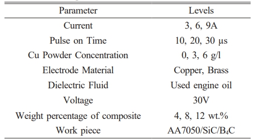
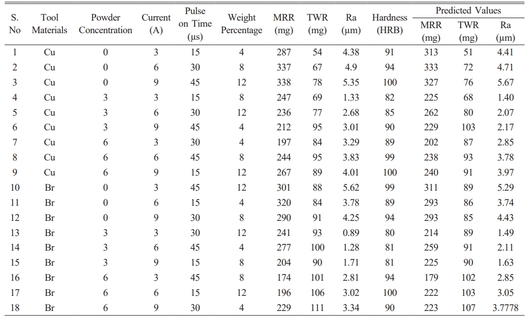
To conduct EDM studies, the composites were sliced to a size of about 10 mm × 25 mm. The experimental runs were designed with the use of a Taguchi mixed orthogonal array. On a die sink EDM machine, a total of 18 trial runs were directed. Responses for the 10 minute machining period were recorded as MRR, TWR, Ra, and MSH. The experiment's process parameters governing the powder concentration, along with current, pulse on time, weight% was shown in Table 2. The UEO was mixed with Cu and used as a dielectric medium. The parameters were selected based on their influence on EDM performance, selected based on the literature survey. Current and pulse on time are crucial parameters that directly affect the heat generation and material removal in EDM. The weight percentage of composites was chosen to investigate the effect of reinforcement on machining performance. Equations (1) and (2) were used to determine the MRR and TWR, which stand for the mass variation of the work piece and tool prior to and following machining to the machined time.

Whereas
Sb and Sa – sample weight before and after milling
The electrode material's Tb and Ta weights before and after cutting
z – Machined time
The Mitutoyo SJ210 surface roughness tester with a 5% accuracy, was used to compute Ra. Ra was measured at six distinct regions, and the average outcome served as the final Ra. Rockwell hardness testing equipment was used to calculate MSH in accordance with ASTM E-18-05. A 100 kg load was applied for a dwell time of 5 seconds at ten different spots, and the MSH number, which represented the average value, was noted.
Material Removal Rate
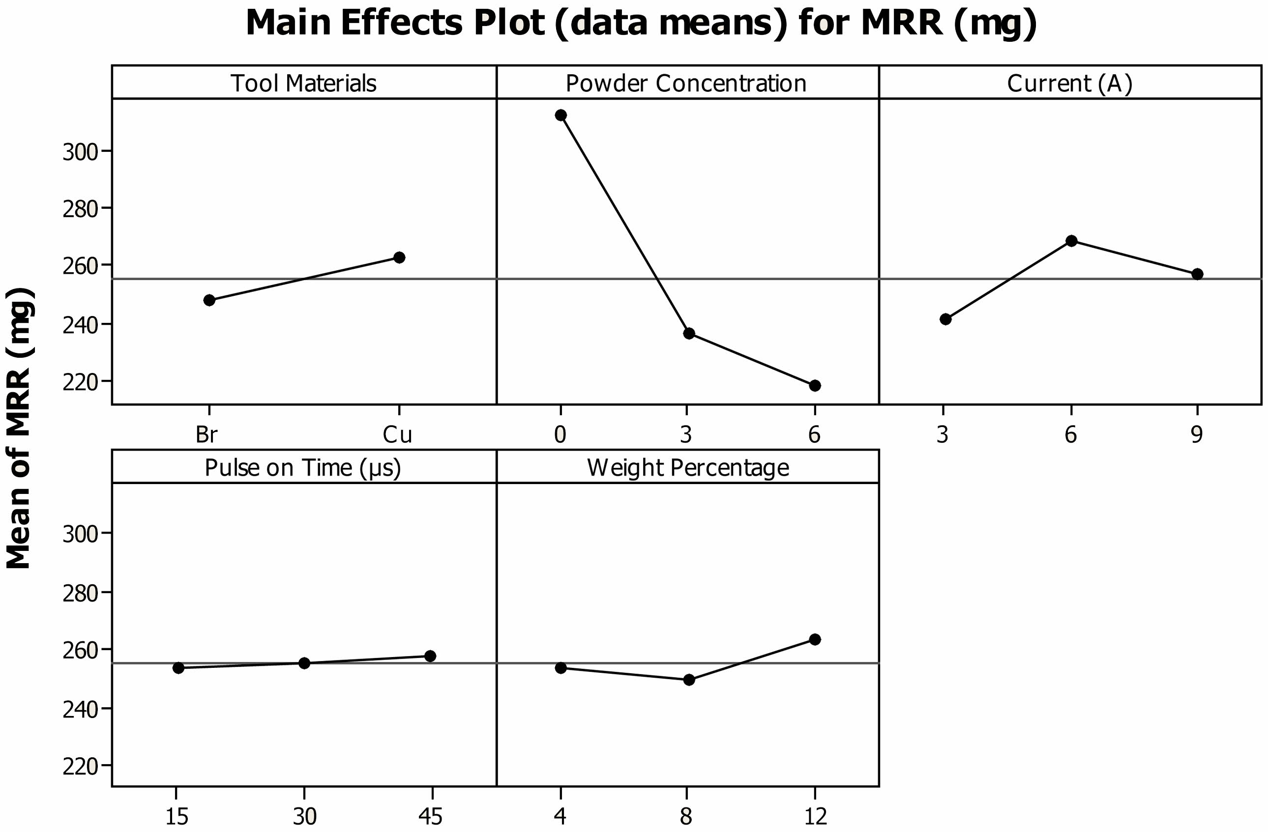
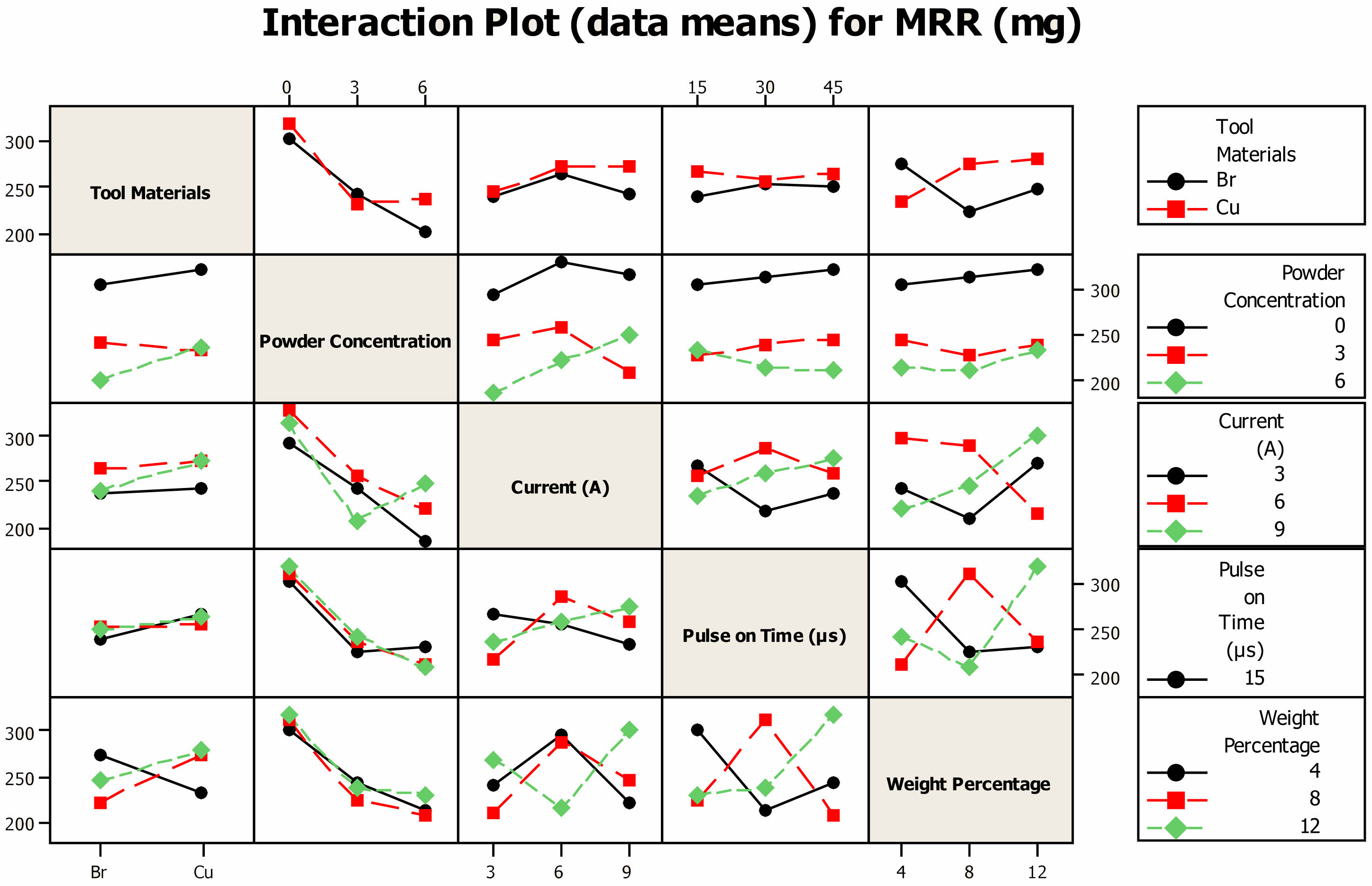
Figure 1 depicts different input parameters have an impact on the MRR of AA7075 hybrid composites. When compared to Br, composites that have been cut using a Cu tool have a high MRR. According to several researchers, Cu creates more heat than Br electrode The MRR is improved by its high thermal conductivity [28]. The mean MRR significantly decreases from 312 mg to 234 mg when 3 g/l of Cu powder is added to UEO, and it decreases to 217 mg when 6 g/l of Cu powder is added. The decrease in MRR at higher concentrations of copper particles can be attributed to the absorption of heat by the particles, which reduces the overall heat available for material removal. Additionally, the increase in spark gap caused by the particles can lead to densification of machined debris, which hinders material removal. MRR typically increases with current and pulse width up to a certain point, beyond which further increases can lead to decreased MRR due to excessive heat generation [29].
The MRR increases until it reaches a 6A saddle point, beyond which it falls as the current increases. This improvement in MRR was related to the fact that a higher current generates heat with a greater intensity, removing the greatest amount of material from the specimen [30]. Massive quantities of materials were removed when the current was increased, caused the machined debris to become denser. This densification of the machined debris lowers the amount of material flushed from the spark gap, which causes remelting, and causes particles to accumulate across the machined region, which lowers MRR. The Ton barely affects MRR, A minimal wear rate of 253 mg was recorded at 15 µs Ton, and when the Ton was increased to 45 µs, it marginally rose to 257 mg. It's interesting to note that the maximum MRR was found when 12% of reinforcing particles were introduced to composites after they were machined [31]. However, compared to Cu mixed medium, Al2O3 mixed UEO dielectric medium has the greatest MRR [32].
Figures 2 show the interaction between distinct input factors on MRR. When the hybrid AA7075/4SiCp/4B4Cp composites were machined with a Ton of 15 µs, an MRR of 238 mg was observed. When the weight proportion of SiC and B4C was 12%, MRR was increased to 244 mg for the same parametric condition. When composites containing 8 wt% were machined with a Ton value of 40 s, the highest MRR was observed [33]. The composites with lower and higher reinforcement weight percentages were machined at currents of 3A and 9A, respectively, to achieve the highest MRR. The MRR was reached for the Ton of 15 µs with a parametric current value of 3A, and it considerably increased to 234 mg for the Ton of 45 µs. The MRR increased when the parametric value was decreased to 15 µs. a lower MRR of 225 mg was found due to the densification of the debris [34]. With increasing current, the MRR increased to a maximum of 271 mg at 7A when the Ton was held at 45 µs.
When powder particles are added, the MRR of hybrid composites was reduced. When AA7075/4SiCp/4B4Cp hybrid composites are machined, their MRR is 26% higher under unmixed UEO dielectric conditions compared to 6 g/l PMEDM. When UEO is not mixed, the MRR increases as the weight % rises; however, adding 6 g/l of Cu particles to UEO has no effect on MRR as the weight percentage of the composites varies. The MRR decreased from 308 mg to 230 mg when the Ton was kept at 15 µs and the powder concentration was increased from its unmixed state to 6 g/l. The MRR rises to 342 mg at 45 µs of unmixed dielectric medium before falling sharply to 238 mg at 6 g/l of powder concentration. The greatest MRR proffered by the specimen, when machined under unmixed UEO conditions at 3A current, and it decreases as the current is upsurged. The MRR at the 3A current was extremely low when 6 g/l were added to the UEO.
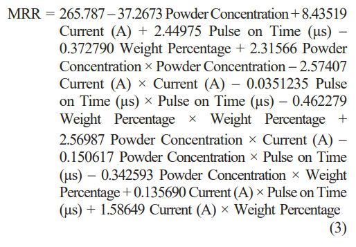
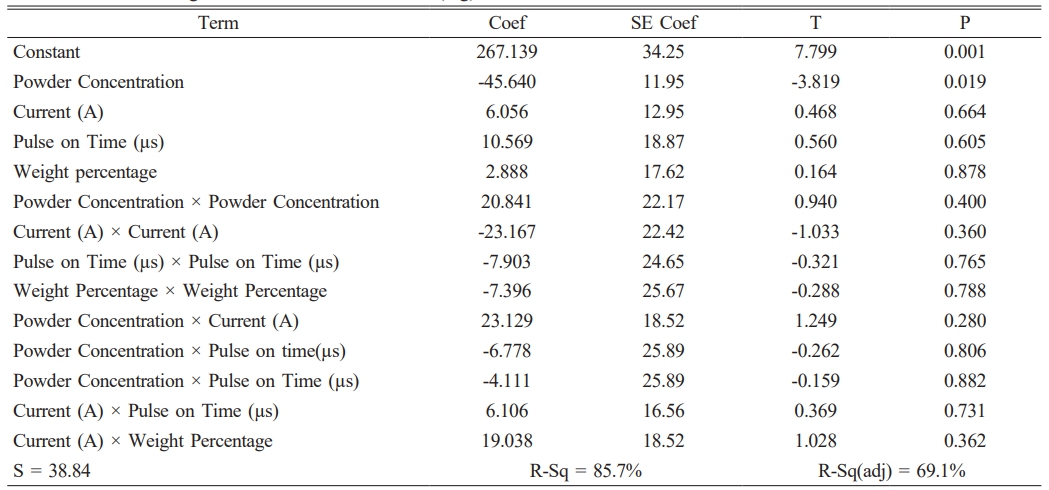
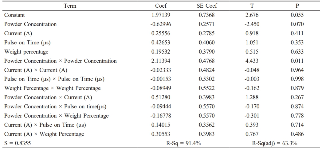
In Table 3, the computed regression coefficient was displayed. It was revealed those variables having a P value under 0.05 were substantially impacting variables since experimental runs were designed with a 95% confidence level. Equation (3) illustrates the mathematical model that was used to forecast MRR. The most important factor that affects MRR, are concentration of the powder as displayed in Table 4 of the ANOVA table.
Tool Wear Ratio
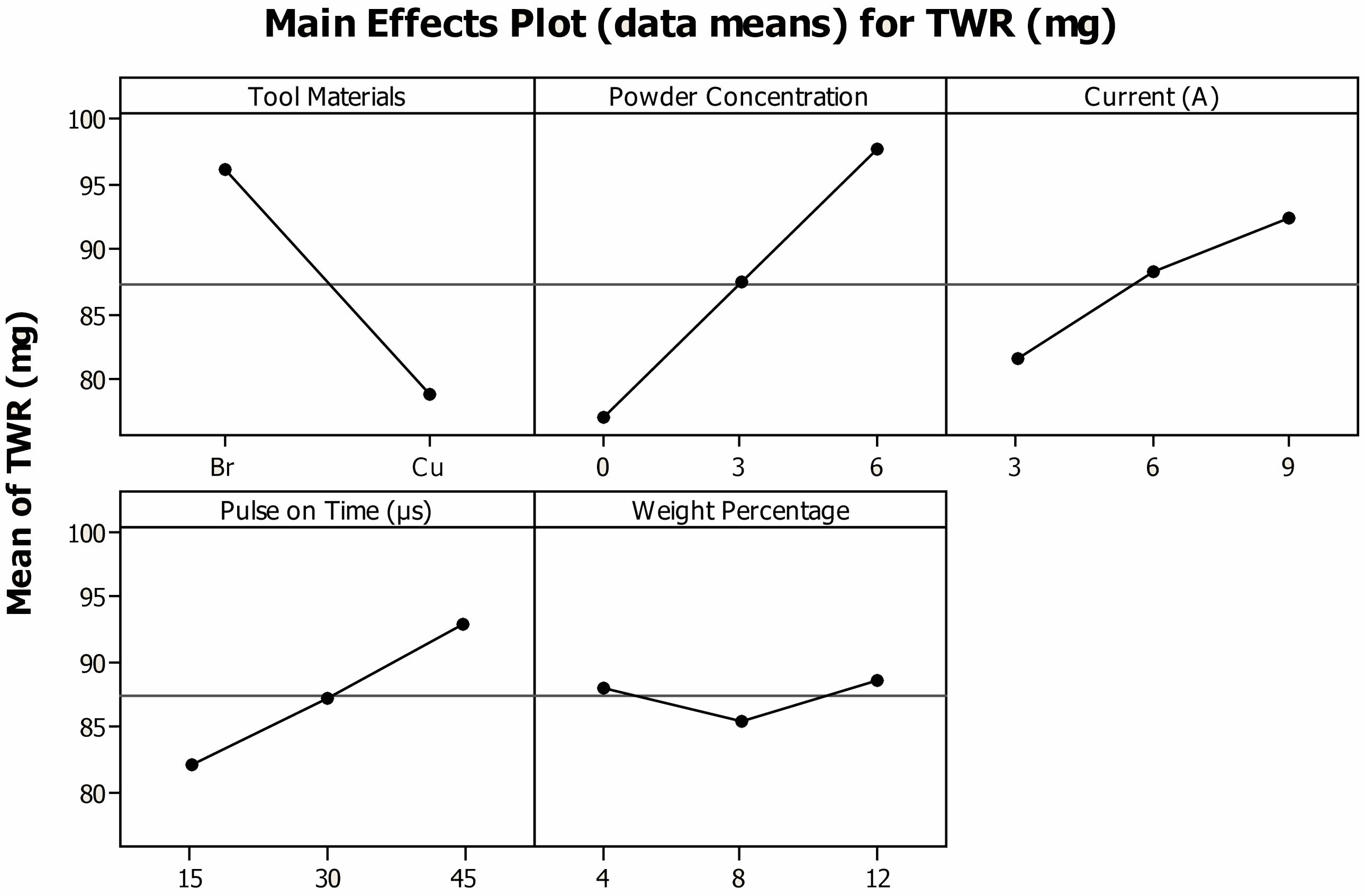
Figure 3 displays impact of different process factors affect TWR. Due to its highest melting temperature, the Cu tool provides less TWR than Br. The Br electrode has the lowest melting point, therefore more materials melted and evaporated from its surface, producing a high TWR. The findings demonstrated that when the dielectric medium is contaminated by Cu particles, the TWR rises and the heat generated is transferred to the electrode rather than the workpiece. The increase in TWR with the addition of Cu powders indicates higher tool wear when using a Cu-mixed dielectric medium. This can have implications for machining efficiency, as increased tool wear can lead to shorter tool life and increased machining costs. However, the transfer of heat to the electrode rather than the workpiece can help in reducing heat-affected zones and improving surface quality. The TWR increases from 81.5 mg to 92.3 mg with a current increase from 3 A to 9 A. Increased current created intense heat, which in turn caused the tool material to evaporate and upsurge TWR [35]. As Ton grows, the TWR rises; a 10% increase in TWR was seen when Ton upsurged from 15 to 45 µs. Higher Ton levels create more heat, which is retained inside the spark gap for a longer duration, hence TWR rises. The inclusion of reinforcing particles barely affects the TWR; regardless of the quantity of reinforcing particles supplied, the TWR ranges from 85 to 88 mg.
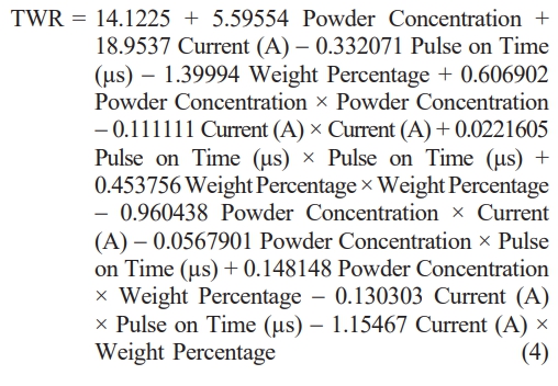
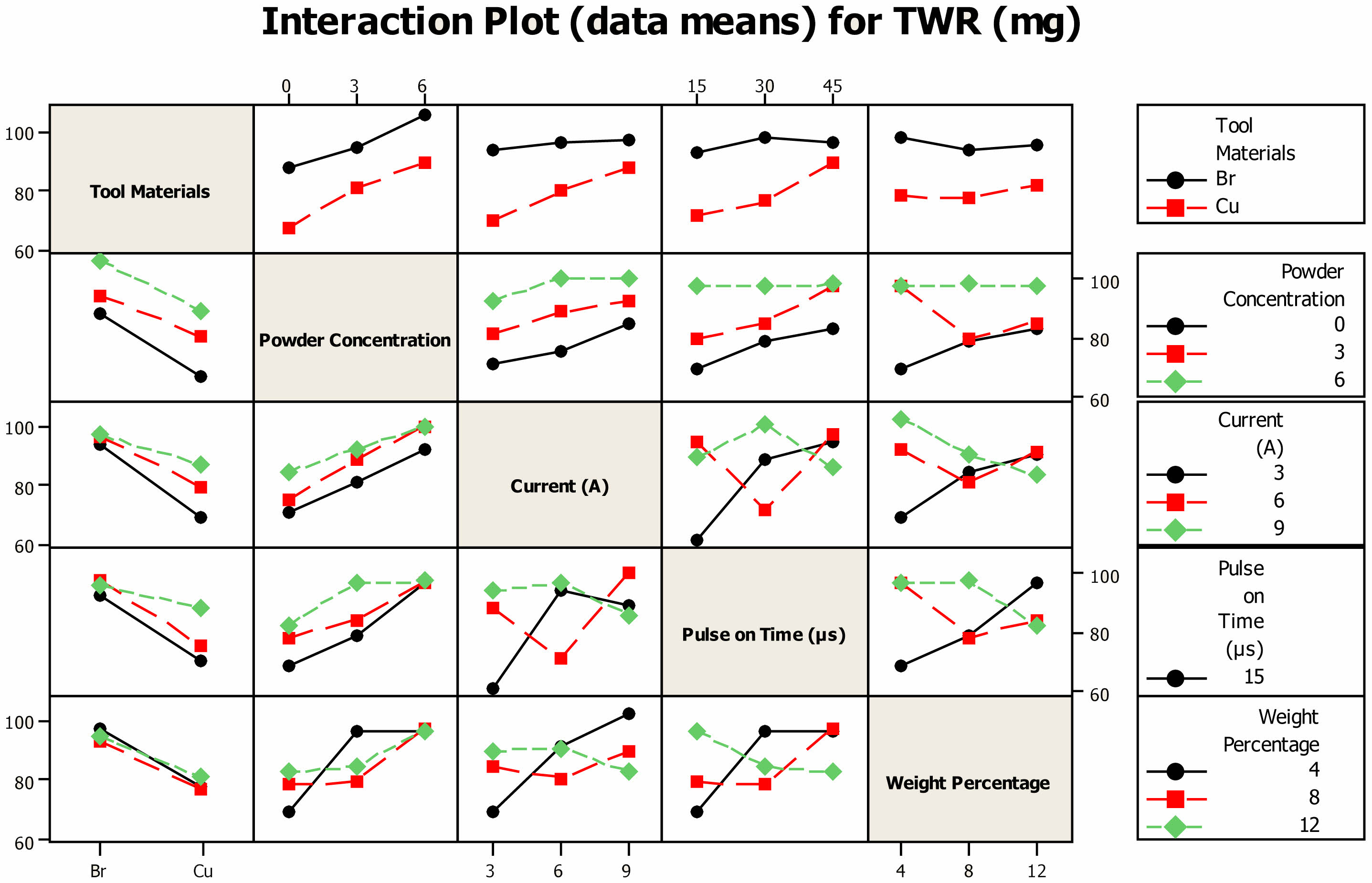
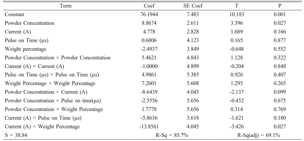
The interplay between various process variables and TWR is depicted in Fig. 4. When the specimen was machined with reinforcing particles (4 wt%), a TWR of 90 mg was observed at Ton 15 µs, and it hardly increased to 91.5 mg when Ton was extended to 45 µs. TWR dropped to 85 mg and 86 mg for Ton values of 15 µs and 45 µs, respectively, with an increase in the weight fraction of reinforcing powders to 12%. When the Ton value was adjusted to 30 µs, the lowest TWR was attained. When the AA7075/4SiC/4B4C hybrid composite was machined at 9A, the maximum TWR of 103 mg was reached in the event of concurrent increases in current and weight %. When the AA7075/12SiC/12B4C specimen was machined at 12A current, the lowest TWR was observed. The minimal TWR for the input variables of current 3A and Ton 15 µs was measured while current and Ton increased sequentially. When the current and Ton increased to 9A and 45 µs, respectively, the TWR was raised to 81 mg and 89 mg. The minimal TWR was 84 mg when the 4 wt% hybrid composites were machined under unmixed UEO, when the weight percentage was raised to 12, it dropped to 75 mg. TWR readings of 98 mg and 96 mg for composites with 4 and 12 wt% were recorded when machined under 6 g/l PMEDM. When Ton was tuned to 30 µs under unmixed UEO, and the minimum TWR of 72 mg was noticed. The minimal TWR of 94 mg was obtained when Cu particles (6 g/l) were added. The lowest TWR of 58 mg was noted when the parametric current was adjusted to 3 A; when powder particles at a concentration of 6 g/l were added to the fluid, the TWR rose to 93 mg. Equation (4) shows the mathematical model that forecast TWR. As shown in Tables 5 and 6, the most significant factors that affect MRR were identified from the ANOVA table as being powder concentration, the interaction between powder concentration and current (A), and the interaction between current and weight percentage.
Surface Roughness
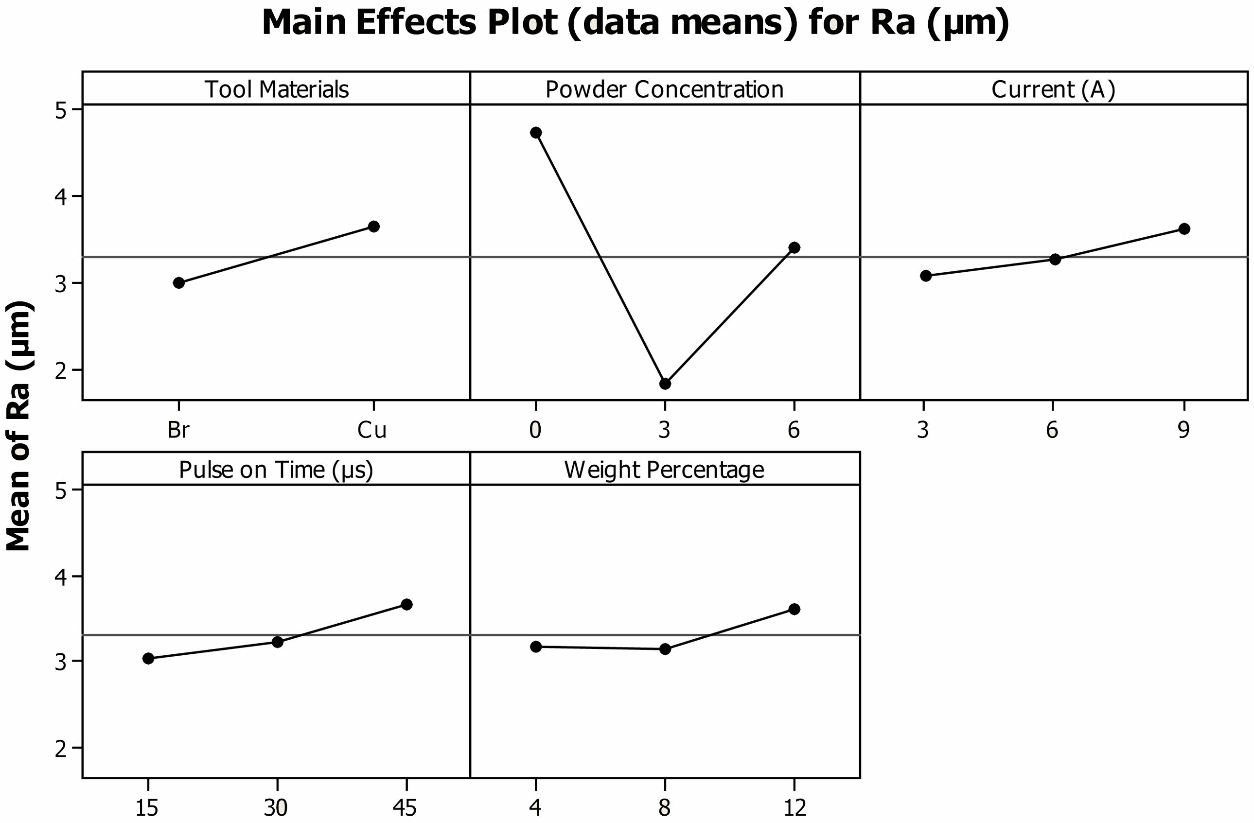
Figure 5 illustrates the composites' Ra. in relation to different process parameters. The hybrid composites of AA7075/SiCp/B4Cp that are machined using brass electrodes have the best surface quality. Brass has a lower thermal conductivity than other electrode materials, therefore less heat was produced as a result, removing less material and providing the highest surface quality [36]. The surface quality improved when Cu particles were added, but after 3 g/l, it started to deteriorate. Due to the heat-absorbing properties of Cu particles, surfaces that are exposed to them are kept at a lower temperature, preventing the development of cracks and craters and enhancing surface quality. Increased spark gap results in complete flushing and eliminates the development of remelted layer. Surface quality varies with machining parameters and electrode materials, with higher thermal conductivity materials generally resulting in better surface quality. Copper electrode with the combination of high melting point, excellent thermal conductivity, low wear, and chemical stability makes it effective in preventing remelted layers and surface defects.
Ra of the composites increases when the discharge current is increased; a mean Ra value of 3.05 m was observed at 3 A current, and it climbed to 3.61 m at 9 A. The increase in Ra value was related to the fact that when the current parametric value rises, it intensifies the heat generated. The Ra plot for the Ton, which is equal to the current, shows that the surface quality degrades as Ton increases from 15 µs to 45 µs. An increase in Ton causes the heat generated to linger in the spark gap for longer duration, which causes fractures and craters to develop and lowers the surface quality [37]. As the weight % of the composites rises, the Ra value rises as well. Surface quality decreases as a result of pitting caused by reinforced particles.
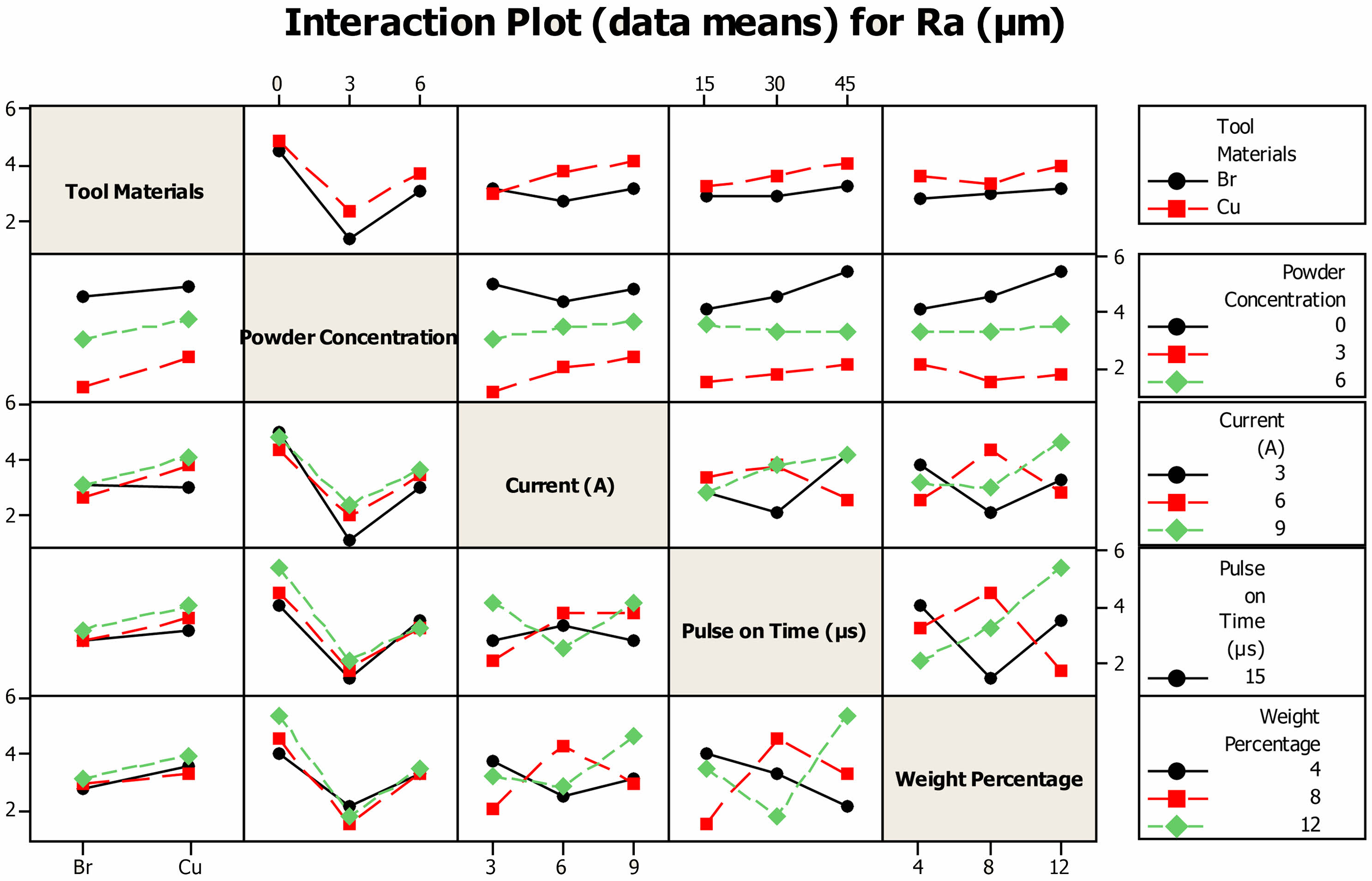
The interactions between various process parameters and its effect on hybrid composites' Ra are shown in Fig. 6. When machining AA7075/4SiCp/4B4Cp with a Ton of 15 µs, a minimum Ra of 1.26 µm was observed. With a 12% increase in particle weight, Ra rises to 1.65 µm for the same parametric value. Ra values rose for reinforced composites containing 4 wt% and 12 wt% when the Ton was set to 45 µs, reaching 2.10 µm and 2.48 µm, respectively. Fig. 7 When the AA7075/12SiC/12B4Cp hybrid composites were machined at 3A current, the Ra was 1.49 µm, and at 9A current, the Ra increased to 2.61 m. In case of the hybrid composites made of AA7075/4SiC/4B4Cp, Ra values were 1.61 µm and 1.671 µm for 3A and 9A currents, respectively. The ideal surface quality of 1.40 µm was machined as indicated in Fig. 8 when the parametric current and Ton values were set at 3A and 15 µs. Ra rises and reaches a minimum of 1.97 µm for a 45 µs Ton by maintaining current as constant as Ton grows. After tuning the current and Ton to 9A and 45 µs, respectively, the Ra further deteriorated to 2.76 m.
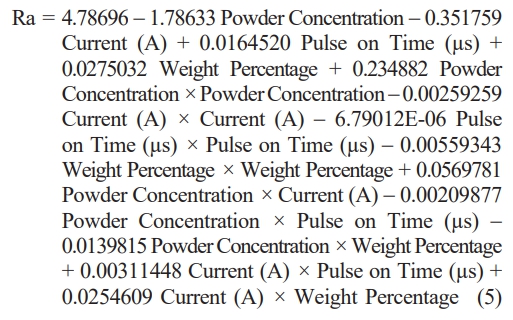
When 3 g/l of Cu powder was added to unmixed UEO, the Ra, which was 4.23 µm, was decreased to 1.69 µm and Ra rises to 3.6 µm when powder concentration is further increased. A minimum Ra of 1.54 µm was reached under 3 g/l PMEDM and 15 µs Ton when there was a concomitant rise in Ton and powder concentration. When machined at 45 µs under unmixed UEO, the surface quality degrades to 5.21 µm. When current and powder concentration interacted, the combination of 3 g/l concentration and 3A current produced the best surface quality. The surface quality achieved under unmixed conditions was 4.92 µm, and when the dielectric fluid had a Cu addition of 6 g/l and Ra of 2.66 µm was obtained. Equation (5) depicts the mathematical model that predicted Ra. The most important component that affects Ra, as seen in Tables 7 and 8, is powder concentration, according to the ANOVA table.
Machined Surface Hardness
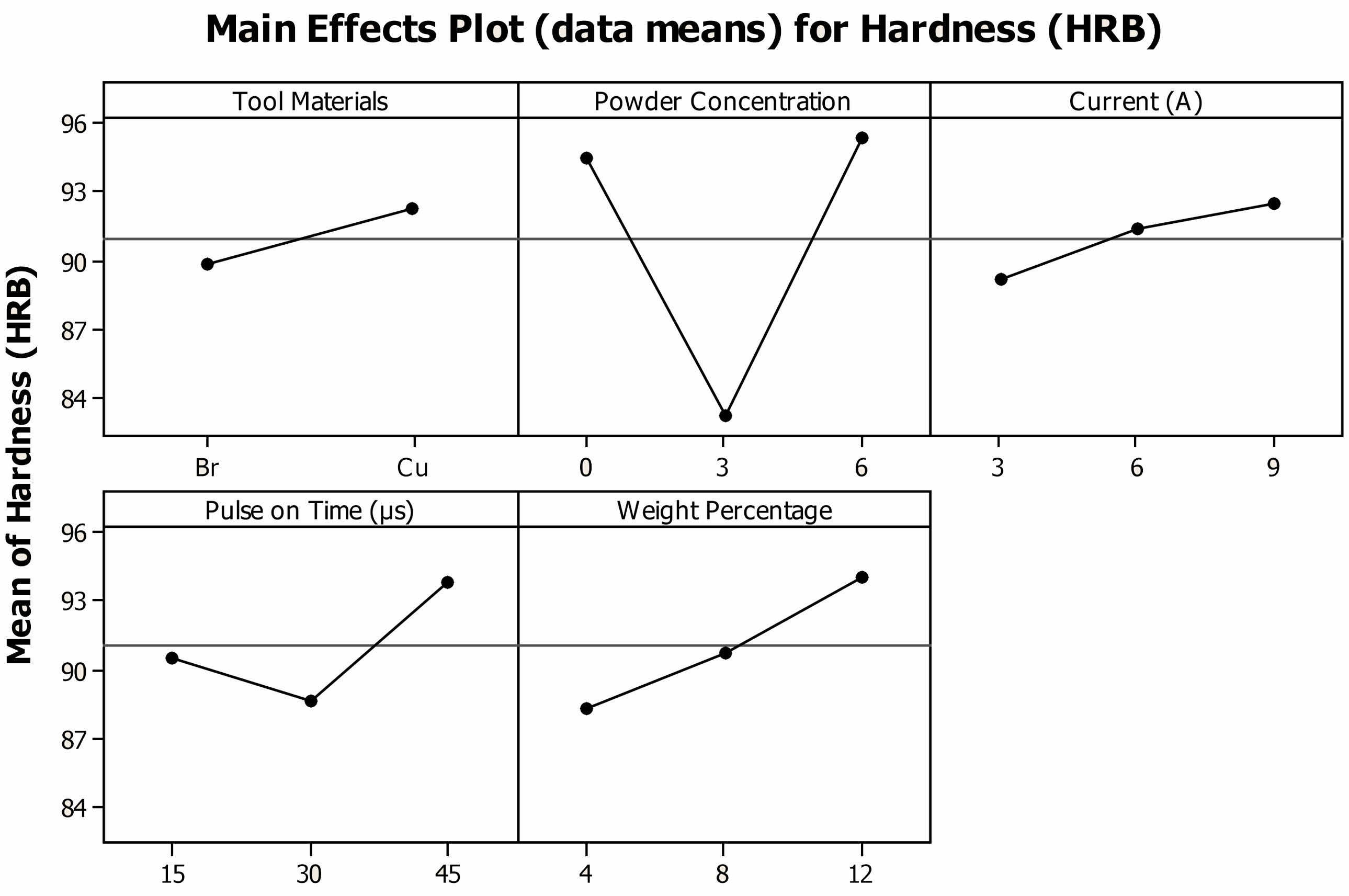
Figure 6 displays the interactions between several process factors that impacts MSH of hybrid composites. Due to the development of a remelted layer on the specimen's copper-tooled surface, the MSH was greater than that of the Br electrode [38]. The specimen with a lower MSH value had a higher Ra value because the two variables were inversely proportional. The specimens attains finest surface quality and lowest MSH value, when machined with 3 g/l PMEDM. The MSH rises as current increases, Ton, and weight %, indicating that an increase in any factors increases Ra [39].
|
Fig. 1 Influence of process parameters on MRR of AA7075/SiCp/B4Cp Hybrid Composites |
|
Fig. 2 nput variables combinatorial effects on MRR of AA7075/SiCp/B4Cp hybrid composites |
|
Fig. 3 Influence of process parameters on TWR of AA7075/SiCp/B4Cp Hybrid Composites. |
|
Fig. 4 nput variables combinatorial effects on TWR of AA7075/SiCp/B4Cp hybrid composites. |
|
Fig. 5 Influence of process parameters on Ra of AA7075/SiCp/B4Cp Hybrid Composites. |
|
Fig. 6 Input variables combinatorial effects on Ra of AA7075/SiCp/B4Cp hybrid composites. |
|
Fig. 7 Influence of process parameters on MSH of AA7075/SiCp/B4Cp Hybrid Composites. |
|
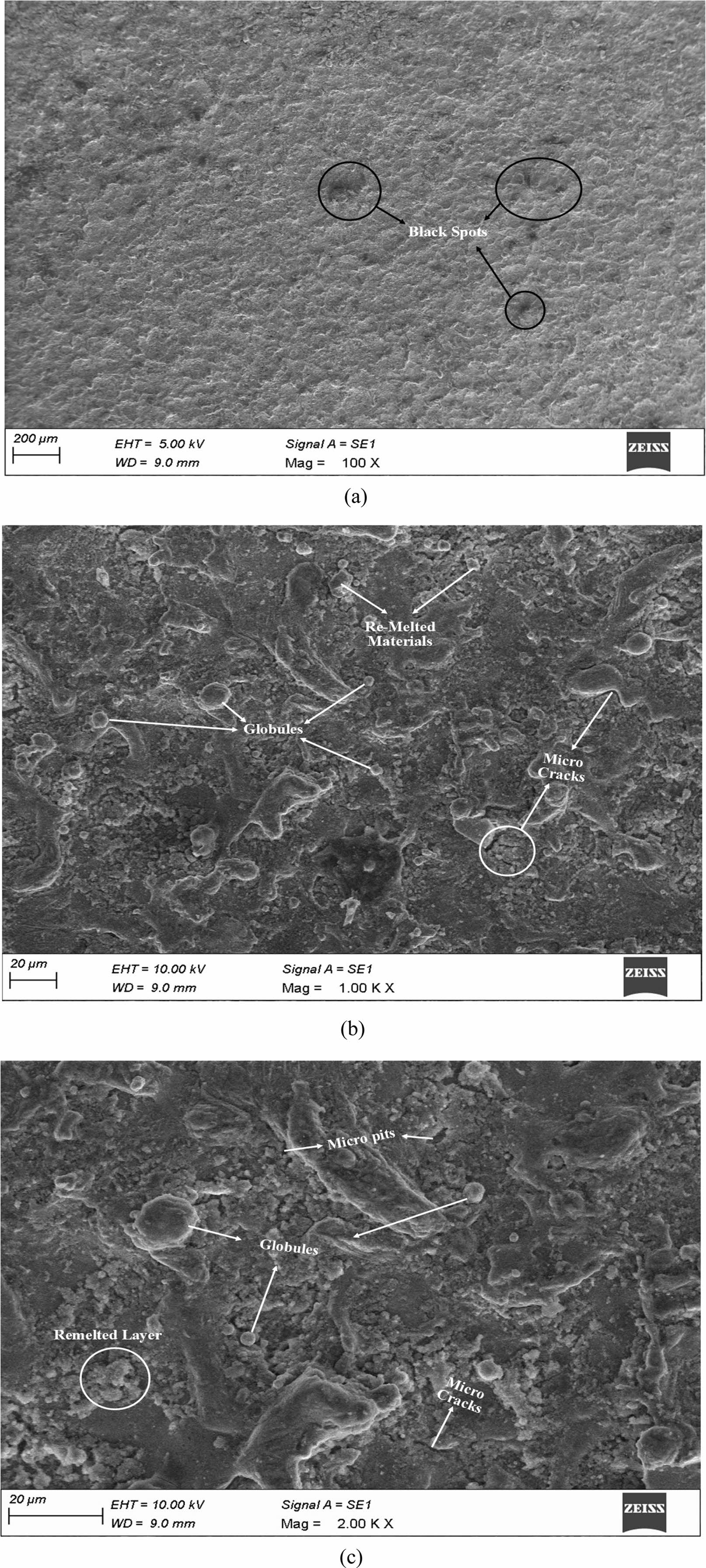
Fig. 8 Surface topography of AA7075 hybrid composites machined at 3 g/l Cu mixed used engine oil dielectric medium (a) At 100X (b) At 1000X (c) At 2000X. |
Figure 8a-c shows the surface topography of AA7075
/4B4C/4SiCp composites machined under 3 g/l Cu mixture. Black dots seen in the surface topography at a 100x magnification. There are no pits or craters, however there are small microcracks that are clearly apparent. The surface roughness was visible as globules, remelted material, and microcracks at the greater magnification of 1000x. Since there was very little remelted layer, the parametric combination provides extremely good surface quality that is highly connected with the experimental findings. Micro pits and black spots are seen at a magnification of 2000x. The remelted layer's creation is plainly visible due to the white hue of the machined specimen's surface. The machined surface powder concentration of 3 g/l also has microglobules, micropits, and microcracks as additional characteristics.
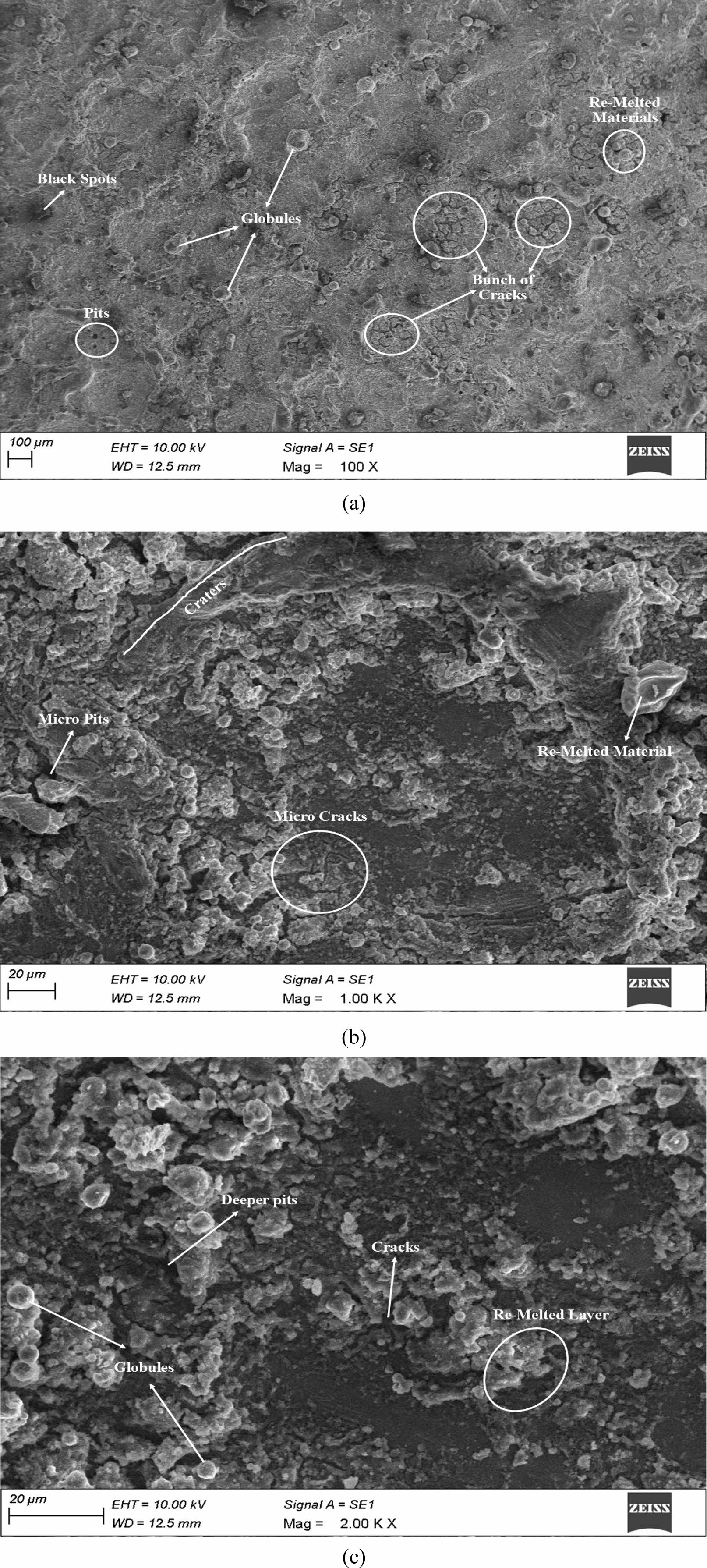
Figure 9a-c shows the surface topography of AA7075/4B4C/4SiCp composites machined under 3 g/l Cu mixture. The picture showed pits, black patches, globules, fissures, and remelted layer at a 100X magnification. At a magnification of 200X, deeper holes, fissures, and remelted material were visible. It demonstrates the integration of particles opens up possibilities for the development of remelted layer. The picture revealed tiny fractures, micro pits, and remelted materials at a greater magnification of 1000X. The machined surface was quite uneven, and an 80 µm was visible.
|
Fig. 9 Surface topography of AA7075 hybrid composites machined at 6 g/l Cu mixed used engine oil dielectric medium (a) At 100X (b) At 1000X (c) At 2000X. |
Using the TOPSIS optimization method, the best parametric combination was identified. The benefit of the recommended strategy is that it continues to include end users in the decision-making process while drawing on the knowledge of policymakers. The best configuration, which includes the best configurations, is a theoretical response in which all desired attributes are connected to the greatest trait estimates in the data set. The worst conceivable arrangement is a hypothetical one where all quality characteristics are related to the data set's lowest estimated properties. Therefore, TOPSIS offers the greatest and most drastic solution among all alternatives. The following are the steps in the optimization procedures.
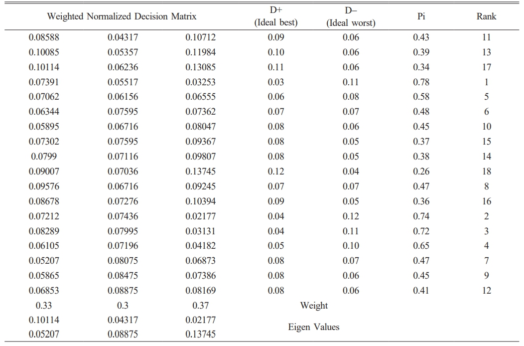
Because there are three alternative outcomes throughout 18 experimental runs, a decision matrix with the dimensions 18X3 was created, as seen in Table 4. The process is then used, beginning with normalizing data sets in accordance with equation (6). J is the number of replies, Bij is the quantity of experimental runs, and Ij is the normalizing matrix. In order to generate a weighted normalized decision matrix (Cij), the weights of each variable were then multiplied by these normalized matrices, as shown in equation (7).

According to equation (8), the weighted normalized matrix for beneficial traits ranges from £+, which is the greatest value, to £-, which is the lowest value. The weighted normalized decision matrix is used to derive the eigenvalues. Equation (9) shows how it was obtained from non-beneficiary attributes in the other manner.
For Beneficiaries

For Non-Beneficiaries

Following this, equation (10) was used to compute the ideal best (P+) and ideal worst (P-) solutions. The numbers in Table 9 and equation (11) indicate that the associated Euclidean distances govern the dispersions between ideals and non-ideals.

The best machining performance was achieved when 3 g/l of conductive copper powder was added to the dielectric fluid and tuning current, pulse on time at 3A and 15s, respectively, and copper was used as the tool material. The identified optimal machining conditions vary depending on workpiece geometries and material compositions. While the study provides valuable insights into optimizing EDM parameters for AA7075 hybrid composites, further research needed to determine the robustness of these conditions across different workpiece types. Factors such as material hardness, composition, and geometry can influence the effectiveness of the optimal conditions.
Following the incorporation of the Cu particles into the UEO dielectric medium, the following findings were seen.
[1] Cu electrodes have lower TWR than Br electrodes due to their higher melting temperatures. Due to an increase in spark gap brought on by the inclusion of particles, TWR decreases. Ra of the specimen machined under Cu mixed UEO was low as a result of full heat distribution and flushing across the machined surface.
[2] The fact that the MSH of the PMEDM composites was low demonstrates that the removal of particles renders the creation of remelted layer impossible. The parametric combination of 3Acurrent, 15s Ton machined with Cu tool and including 3 g/l of Cu powder delivers the highest performance, according to the TOPSIS optimization approach.
Research could focus on optimizing EDM parameters for other materials and workpiece geometries, as well as exploring the use of UEO-based EDM in combination with other incorporated particles. UEO can be used as a dielectric medium by combining the machining processes such as ultrasonic aided EDM.
- 1. M.K. Surappa and Mirle Krishnegowda, Sadhana. 28[3] (2003) 319-334.
-

- 2. J. Zheng, W. Zheng, A. Chen, J. Yao, Y. Ren, C. Zhou, and Z. Zhang, Sci. Total. Environ. 722 (2020) 137897.
-

- 3. S. Sun and M. Brandt Encycl. Nanotechnol. (2013) 35-96.
-

- 4. R. Melentiev and F. Fang, CIRP J. Manuf. Sci. Technol. 22 (2018)1-20.
-

- 5. R.P. Singh and S. Singhal, Mater. Manuf. Processes. 32[3] (2017) 309-326.
-

- 6. X.U. Zhengyang and W.A.N.G. Yudi, Chin. J. Aeronaut. 34[2] (2021) 28-53.
-

- 7. J.B. Valaki and P.P. Rathod, Int. J. Adv. Manuf. Technol. 87[5] (2016) 1509-1518.
-

- 8. C. Li, X. Xu, Y. Li, H. Tong, S. Ding, Q. Kong, and J. Ding, J. Alloys Compd. 783 (2019) 95-102.
-

- 9. C. Somu and R. Ranjith, ECS J. Solid State Sci. Technol. 11[5] (2022) 053010.
-

- 10. G. Kibria, B.R. Sarkar, B.B. Pradhan, and B. Bhattacharyya, Int. J. Adv. Manuf. Technol. 48[5] (2010) 557-570.
-

- 11. S. Chakraborty, V. Dey, and S.K. Ghosh, Precis. Eng. 40 (2015) 1-6.
-

- 12. F.N. Leão and I.R. Pashby, J. Mater. Process. Technol. 149[1-3] (2004) 341-346.
-

- 13. M. Bhaumik and K. Maity, Eng. Sci. Technol. Int. J 21[3] (2018) 507-516.
-

- 14. S. Kumar, H.K. Dave, and K.P. Desai, Int. J. Adv. Manuf. Technol. 87[5] (2016) 1609-1620.
-

- 15. M. Hadad, L.Q. Bui, and C.T. Nguyen, Int. J. Adv. Manuf. Technol. 95[5] (2018) 2093-2104.
-

- 16. T. Muthuramalingam and B. Mohan, Arch. Civ. Mech. Eng. 15[1] (2015) 87-94.
-

- 17. V. Srivastava and P.M. Pandey, J. Manuf. Processes. 14[3] (2012) 393-402.
-

- 18. U. Ragavendran, R.K. Ghadai, A.K. Bhoi, M. Ramachandran, and K. Kalita Trans. Can. Soc. Mech. Eng 43[1] (2018) 13-25.
-

- 19. M. Prabhakar, R. Ranjith, and S. Venkatesan, Mater. Res. Express. 8[8] (2021) 086505.
-

- 20. M. Bhaumik and K. Maity, World J. Eng 18[1] (2017) 50-57.
-

- 21. S. Tripathy and D.K. Tripathy, Eng. Sci. Technol. Int. J. 19[1] (2016) 62-70.
-

- 22. T.T. Hong, N.V. Cuong, B.T. Danh, L.H. Ky, N.H. Linh, V.T. Lien, and N.M. Cuong, Mater. Sci. Forum. 1018 (2021) 51-58.
-

- 23. N.S. Khundrakpam, S. Kumar, A. Singh, and G.S. Brar, Int. J. Emerg. Technol. Adv. Eng. 4[3] (2014) 541-546.
- 24. A. Singh and R. Singh, Int. J. Innov. Res. Sci. Technol. 2[3] (2015) 164-169.
- 25. K.M. Senthilkumar, N. Kathiravan, L. Girisha, and M. Sivaperumal, J. Ceram. Process. Res. 23[4] (2022) 541-545.
-

- 26. M.L. Jeswani, Wear. 55[1] (1979) 153-161.
-

- 27. H.K. Kansal, Sehijpal Singh, and Pradeep Kumar, J. Manuf. Processes. 9[1] (2007) 13-22.
-

- 28. C. Somu, R. Ranjith, P.K. Giridharan, and M. Ramu, Surf. Topogr. Metrolog. Prop. 9[3] (2021) 035025.
-

- 29. S. Patel, D. Thesiya, and A. Rajurkar, Aust. J. Mech. Eng. 16[1] (2018) 21-30.
-

- 30. S. Kumar, S. Gurusamy, V. Sivakumar, and S.M. Vaiyapuri, J. Ceram. Process. Res. 23[6] (2022) 869-877.
-

- 31. A. Abdudeen, J.E. Abu Qudeiri, A. Kareem, T. Ahammed, and A. Ziout, Micromachines. 11[8] (2020) 754.
-

- 32. P.P. Shantharaman, V. Anandakrishnan, S. Sathish, and M. Ravichandran, J. Ceram. Process. Res. 23[5] (2022) 589-594.
-

- 33. V. Vidhata, K. Shubham, M. Lalchandani, K. Sharma, and M.S. Chandrashekara, Int. J. Recent Adv. Multidiscip. Top. 2[7] (2021) 13-16.
- 34. S. Devgan, A. Mahajan, and S. S. Sidhu, Appl. Phys. A. 127[11] (2021) 1-15.
-

- 35. S. Devgan, A. Mahajan, G. Singh, G. Singh, and S. S. Sidhu, Sustainable Machining Strategies for Better Performance (2022) 207-217.
-

- 36. Anoop Johny and C. Thiagarajan, J. Ceram. Process. Res. 23[4] (2022) 443-458.
-

- 37. P. Suresh and R.K. Venkatesh, SC. J. Mech. Eng. 71[2] (2021) 305-316.
-

- 38. R. Jayachitra, R. Ranjith, B. Ramesh, and R. Lawanya, Surf. Eng. 38[5] (2022) 482-498.
-

- 39. S. Sharma, U.K. Vates, and A. Bansal, Mater. Today Proc. 45 (2021) 757-763.
-

 This Article
-
2024; 25(4): 499-511
Published on Aug 31, 2024
- 10.36410/jcpr.2024.25.4.499
- Received on Dec 8, 2023
- Revised on May 9, 2024
- Accepted on Jun 5, 2024
 Services
- Abstract
introduction
experimental work
results and discussion
surface topography
technique for order of preference by similarity to ideal solution (topsis)
conclusions
scope for future work
- References
- Full Text PDF
Shared
 Correspondence to
- Udhaya Chandran R.M.
-
Assistant Professor, Department of Mechanical Engineering, Adithya Institute of Technology, Coimbatore
Tel : +919597864424 - E-mail: rmudhayachandran@gmail.com





 Copyright 2019 International Orgranization for Ceramic Processing. All rights reserved.