- Investigation on electrochemical performances of dry-processed LiNi0.6Co0.2Mn0.2O2 and graphite electrode
Chea-Yun Kanga, Kyong-Nam Kimb,* and Seung-Hwan Leea,*
aDepartment of Battery Convergence Engineering, Kangwon National University, Chuncheon, 24341, Republic of Korea
bDepartment of Semiconductor Engineering, Daejeon University, Daejeon, Republic of KoreaThis article is an open access article distributed under the terms of the Creative Commons Attribution Non-Commercial License (http://creativecommons.org/licenses/by-nc/4.0) which permits unrestricted non-commercial use, distribution, and reproduction in any medium, provided the original work is properly cited.
The conventional method for fabricating lithium-ion battery (LIB) electrodes heavily relies on the wet coating process, which involves the use of the environmentally harmful and toxic solvent N-methyl-2-pyrrolidone (NMP). Apart from being unsustainable, this costly organic solvent significantly inflates the production expenses of batteries due to the need for drying and recycling throughout the manufacturing process. In this report, we introduce a commercially viable and environmentally sustainable dry process technique. This method utilizes a (polytetrafluoroethylene)PTFE as a dry powder. We successfully synthesize LiNi0.6Co0.2Mn0.2O2 and graphite electrodes by dry-processing using the fiberization of polytetrafluoroethylene. The produced electrodes exhibit a porous structure, and uniform dispersion of polytetrafluoroethylene was confirmed through F. The structural/electrochemical stability is observed at the driving voltage of the electrodes. The initial charge-discharge and cyclic voltammetry are measured and analyzed to evaluate the electrochemical performances. As a result, we could conclude that the synthesized electrodes could be sufficiently applicable to next-generation energy storage devices.
Keywords: LiNi0.6Co0.2Mn0.2O2, Graphite, Dry-processing, Fiberization, Polytetrafluoroethylene.
Due to the expansion of the electric vehicle market, there is a continuous increase in demand for high-energy-density batteries. One simple and effective way to enhance the energy density of Lithium-ion Batteries (LIBs) is to increase the thickness of the electrodes [1]. However, when creating thick electrodes using traditional wet processes, the evaporation of a large amount of organic solvents during electrode drying causes an uneven distribution of conductive agents and binders within the electrode. This results in a weakened mechanical and electrochemical network among the active materials, leading to degraded electrochemical performance and structural deterioration. Therefore, research into electrode manufacturing using dry processes, which do not involve solvents, is being actively pursued to address these issues [2].
The expansion of the electric vehicle market has led to a continuous increase in demand for high-energy-density batteries. One simple and effective method to enhance the energy density of lithium-ion batteries (LIBs) is to increase the thickness of the electrodes. However, when producing thick electrodes using the conventional wet process, the evaporation of a large amount of organic solvent during electrode drying causes an uneven distribution of conductive additives and binders within the electrode [1]. This results in weakened mechanical and electrochemical networks among the active materials, leading to degraded electrochemical performance and structural deterioration. Therefore, research is actively being conducted on electrode manufacturing using a dry process that does not use solvents in order to solve these issues.
The binder commonly used in the conventional wet process is PVDF (polyvinylidene fluoride), which is a fluoropolymer with excellent physical and chemical stability. It is stable and does not decompose at the operating voltages used in batteries, offering the advantage of outstanding electrochemical stability. However, PVDF binder cannot be applied to dry electrodes as it needs to be dissolved and dispersed in a solvent, NMP, for the dry process. PVDF possesses excellent thermal and durability properties due to its C-F bonds, making it electrochemically superior and used in batteries and supercapacitors [3, 4]. The use of PTFE, which can manufacture the components of an electrode in a uniform manner without the use of solvents, is being extensively researched. This non-solvent system is possible due to PTFE's unique fibrillation characteristic, which is the formation of fibers. PTFE exhibits two phase transition temperatures (19 °C and 30 °C), and above 19 °C, applying stress among polymer powders causes fibrillation. Applying this to electrode manufacturing allows for the mixing of active material, conductive additive, and binder without solvents, enabling the uniform mixing of components to fabricate electrodes [2].
Therefore, in this paper, we applied PTFE to LiNi0.6Co0.2Mn0.2O2 (NCM) cathodes and graphite anodes to manufacture electrodes using a dry process, and measured their structural and electrochemical performance.
To obtain dry-processed NCM and graphite, commercialized NCM and graphite active materials were used. The cathode and anode powders, super P, and PTFE were mixed at a ratio of 70 wt% : 3 wt% : 27 wt% at 1400 rpm for 60 minutes. Afterwards, the mixture was pressed using a steel rod to facilitate the fibrillation of PTFE. The thickness of both samples is controlled by the gap between the rolls of the calendering machine.
Both half-cells and full cells were assembled using 2032 coin cells in an argon-filled glove box, with the concentration of water and oxygen maintained below 0.01 ppm. For the half-cell and full-cell tests, a cellulose film, Li metal, and 1 M LiPF6 in ethylene carbonate (EC): ethyl methyl carbonate (EMC) were used as the separator, counter electrode, and liquid electrolyte, respectively. For the full-cell tests, the capacity ratio of anode to cathode (N/P ratio) was set to 1.2:1.
The microstructure of both electrodes was measured using FE-SEM (Field Emission Scanning Electron Microscopy), while the capacity/dQ/dV and CV (Cyclic Voltammetry) were measured using an electrochemical machine and electrochemical workstation, respectively.
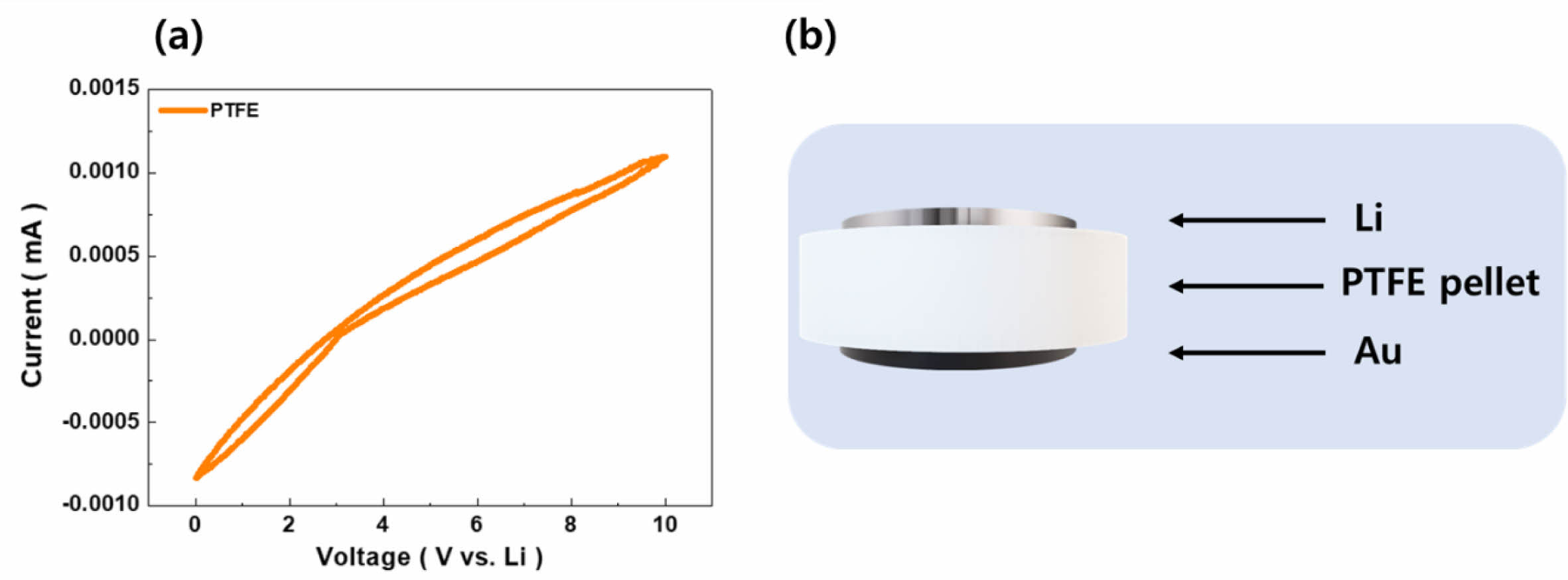
The comprehensive cyclic voltammetry (CV) tests were meticulously planned and executed. The results of these tests are illustrated in Fig. 1(a), which captures the electrochemical behavior of electrodes incorporating PTFE as a binder. Concurrently, Fig. 1(b) offers a schematic representation of the PTFE powder, compressed into pellets (Ø16 mm in diameter) specifically designed for these experiments. For the CV tests, an Au electrode was selected as the working electrode due to its inert nature and high conductivity, ensuring minimal interference with the electrochemical measurements. As a counter electrode, a lithium metal disc (Ø16 mm) was chosen, which serves as a reference standard in lithium-ion battery research due to its direct relevance to the battery's anodic reactions [5]. Measurements were carried out over a voltage range of 0 to 10 V, at a scan rate of 0.1 mV/s. Remarkably, the CV curves displayed a linear response across this entire voltage range, with no evidence of PTFE decomposition. This linear behavior is particularly significant, as it demonstrates the chemical stability of PTFE under the conditions tested, suggesting that it does not undergo any electrochemical reactions that would compromise the integrity of the electrode. Such stability is crucial for both the anode and cathode materials, which operate within specific voltage ranges in a lithium-ion battery. The anode typically functions within a voltage range of 0.005 to 2 V, whereas the cathode operates at higher voltages, ranging from 3.0 to 4.3 V [6-8]. The absence of any decomposition peaks or nonlinear behavior in the CV curves within these voltage ranges indicates that PTFE maintains its structural and chemical integrity, thereby supporting the formation of stable mechanical and electrochemical networks within the electrode.
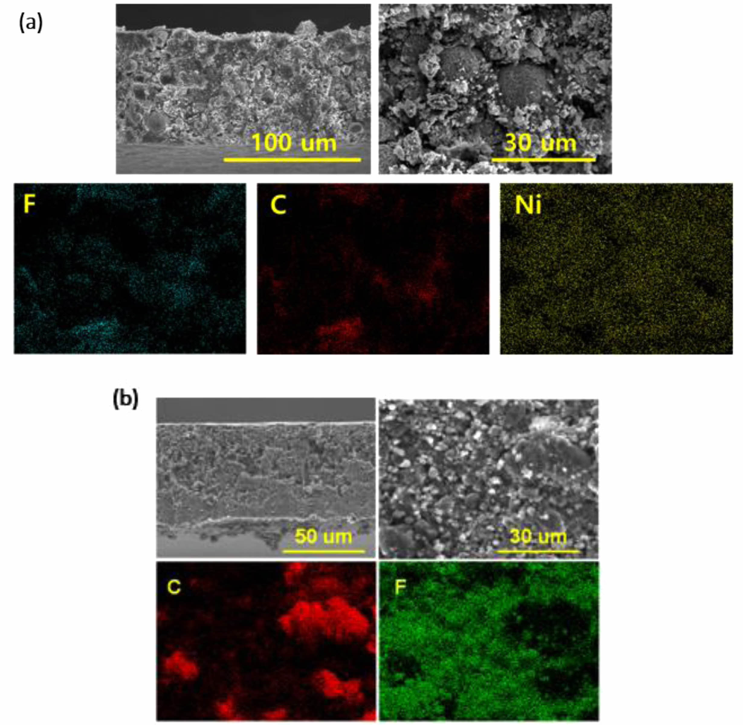
Fig. 2 shows the cross-sectional FE-SEM images of the dry electrode. In case of anode, the presence of PTFE fibrillation was distinctly observed, showcasing its fibrous structure integrated within the electrode matrix. This observation was crucial as it indicates the successful incorporation and distribution of PTFE throughout the anode [2]. Furthermore, utilizing EDS mapping, it was possible to verify that the fluorine (F) element, characteristic of PTFE, exhibited a uniform distribution across the entire electrode. This uniform dispersion of PTFE throughout the anode suggested that the PTFE binder achieved high dispersibility within the electrode, potentially contributing to enhanced electrode performance. Conversely, for cathode, it is difficult to confirm the fibrillation of PTFE [4, 7]. This difficulty arose due to the higher concentration of conductive additives present in the anode compared to the cathode, potentially masking the distinct features of PTFE fibrillation. However, they revealed a consistent distribution of the fluorine (F) element throughout the cathode structure, indicating that PTFE was uniformly dispersed within the electrode matrix.
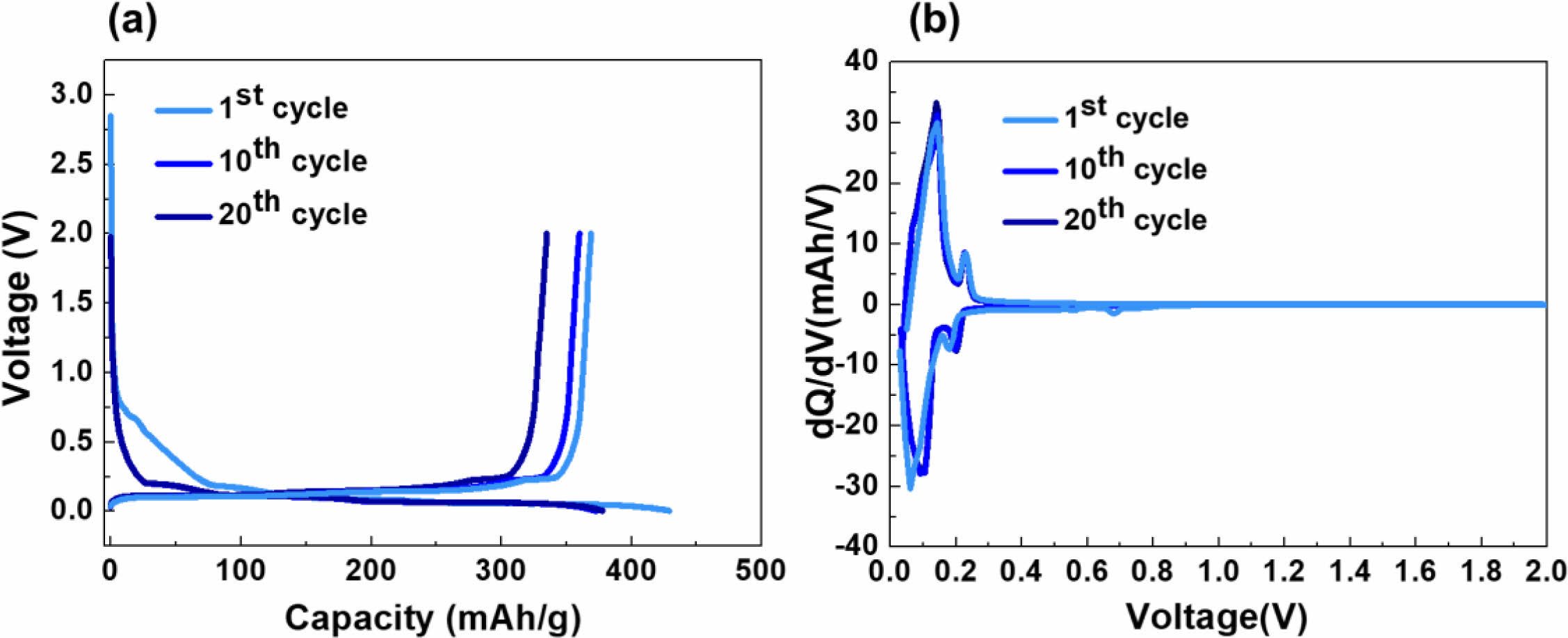
Figure 3 depicts the (a) charge/discharge curves and (b) dQ/dV measurement results of the dry cathode. The electrolyte used was a commercially available electrolyte for lithium-ion batteries, consisting of 1 M LiPF6 in EC:DEC:DMC (1:1:1 vol.%). During the initial cycle, a voltage plateau around 0.7 V was observed, with a Coulombic efficiency of 85%. This observation can be attributed to the interaction between PTFE and lithium during the lithiation process of graphite, leading to the formation of C/LiF, as indicated in Equation (1). The reason for such sub-reactions lies in the higher electron accepting ability of PTFE binder compared to commonly used solvent-based binders such as PVDF (Polyvinylidene fluoride) or CMC (Carboxymethyl cellulose) [9].

However, in subsequent cycles, the Coulombic efficiency increased to 92% and 95%, indicating that the sub-reaction likely only affects the initial cycles. This is further supported by the dQ/dV analysis, where a reduction peak around 0.7 V was observed only in the first cycle, followed by a consistent peak up to 20 cycles, suggesting stability.
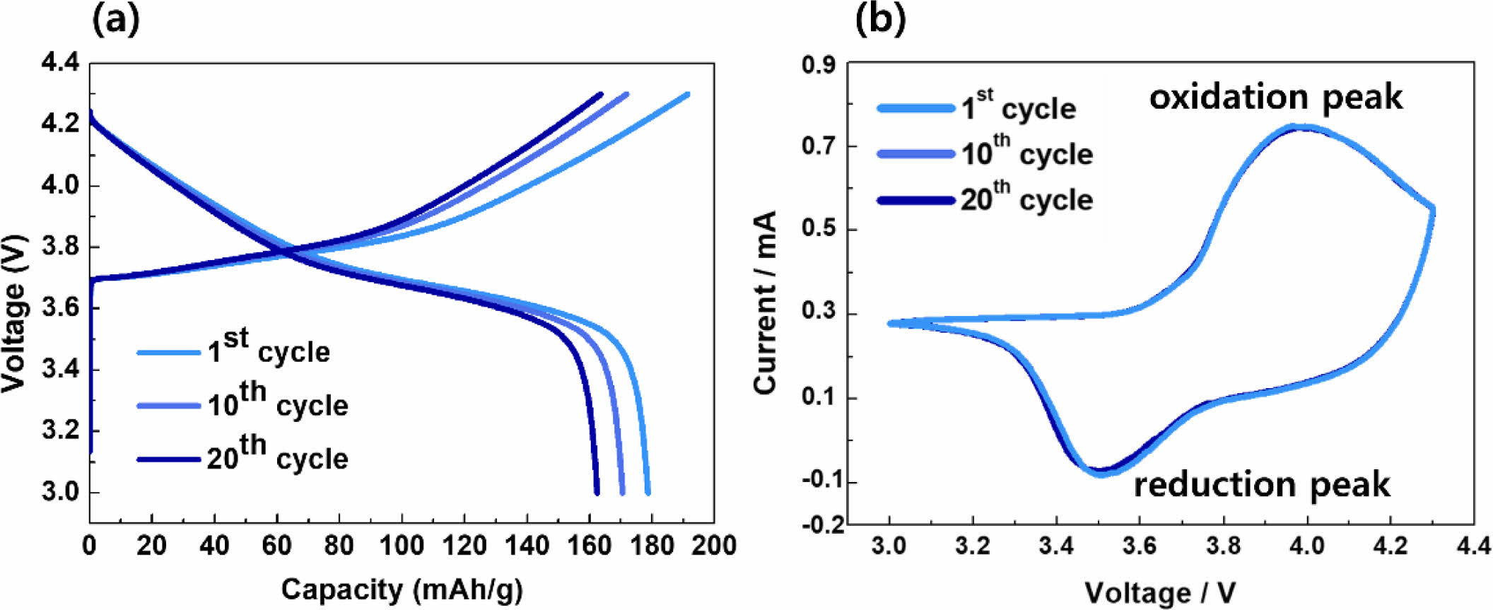
Figure 4 presents the (a) charge/discharge curves and (b) dQ/dV measurement results of the cathode. After 20 cycles, the discharge capacity reached 158 mAh/g, with a Coulombic efficiency of 96%. Remarkably, there was no significant decrease in capacity compared to the first cycle, which can be attributed to the consistent positions of the oxidation/reduction peaks, as observed in cyclic voltammetry (CV). This stable performance over multiple cycles indicates the robustness and durability of the cathode. The absence of significant changes in the oxidation/reduction peaks suggests that the electrochemical processes occurring within the cathode remain consistent and well-defined, contributing to the sustained capacity and high Coulombic efficiency observed throughout the cycling tests [10].
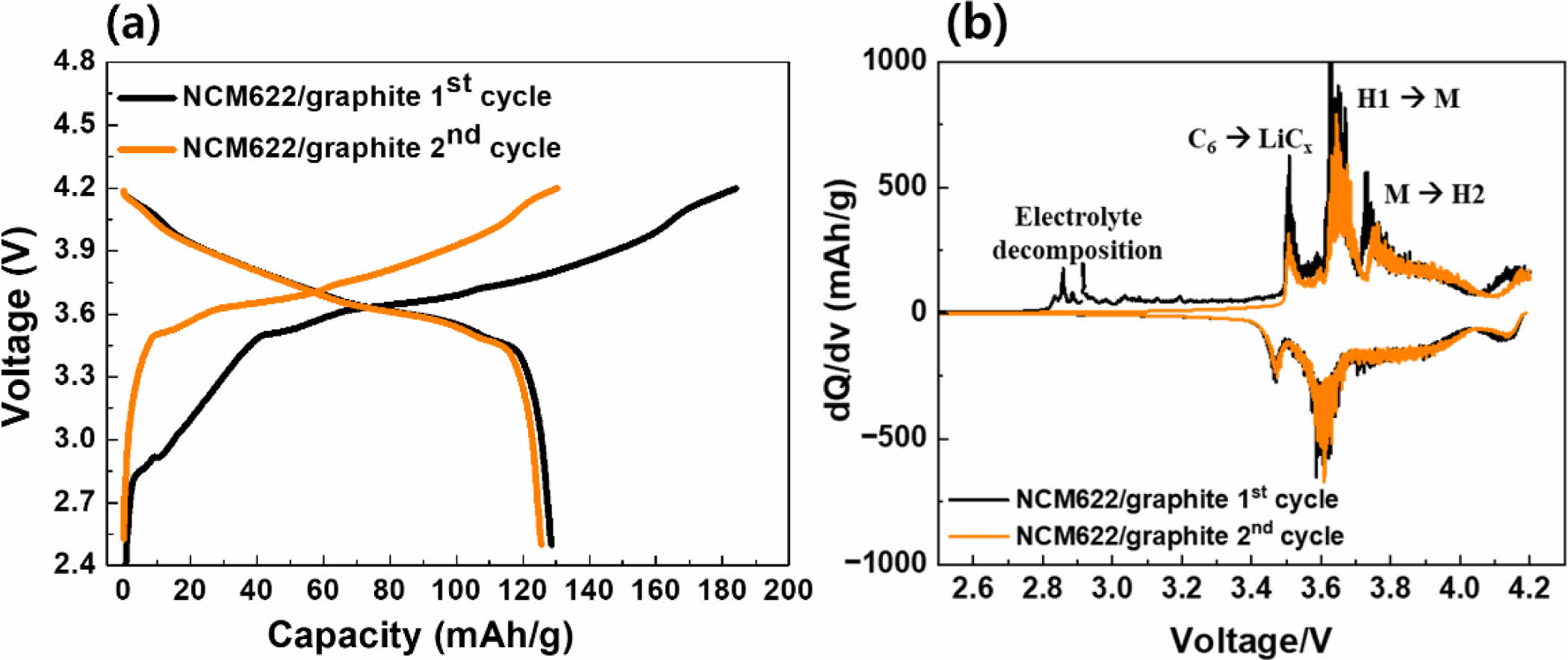
Figure 5 illustrates the electrochemical performance test of the full-cell fabricated with dry electrodes. The initial charge/discharge results revealed a significant decrease in discharge capacity due to irreversible processes at the cathode. This decrease is attributed to the formation of the solid electrolyte interphase (SEI) layer on the cathode and the decomposition of the electrolyte, as indicated by the (b) dQ/dV graph. The observation of a pronounced decrease in discharge capacity suggests that the initial cycles induce irreversible reactions at the cathode, likely due to the formation of SEI and electrolyte decomposition [3, 5, 11]. This phenomenon is evident from the dQ/dV graph, particularly at the onset of electrolyte decomposition peaks during the initial cycles.
|
Fig. 1 Electrochemical stability of PTFE |
|
Fig. 2 SEM images and EDS mapping of dry (a) NCM cathode and (b) graphite anode. |
|
Fig. 3 (a) charge/discharge and (b) dQ/dV curves of dry-processed graphite anode |
|
Fig. 4 (a) charge/discharge and (b) CV curves of dry-processed NCM cathode. |
|
Fig. 5 (a) charge/d.ischarge and (b) CV curves of dry-processed NCM cathode/graphite anode full-cell. |
We fabricated dry NCM cathodes and graphite anodes using a straightforward process involving the fibrillation of PTFE. The electrochemical stability of PTFE was confirmed in the range of 0-10 V, and the capacities of the graphite anode and NCM cathode were measured at the 1st, 10th, and 20th cycles. To verify reversibility, dQ/dV and CV measurements were conducted for graphite and NCM, respectively. Half-cell tests demonstrated the performance of dry electrodes to be nearly equivalent to that of wet electrodes, and full-cell tests using both samples revealed that the performance degradation mechanisms of the full cell could be attributed to i) electrolyte decomposition and ii) the transformation of graphite anode's C to LiCx. Based on these findings, we aim to develop improved dry electrodes by addressing these issues.
- 1. F. Hippauf, B. Schumm, S. Doerfler, H. Althues, S. Fujiki, T. Shiratsuchi, T. Tsujimura, Y. Aihara, and S. Kaskel, Energy Storage Mater. 21 (2019) 390.
-

- 2. Y. Kobayashi, S. Seki, Y. Mita, Y. Ohno, H. Miyashiro, P. Charest, A. Guerfi, and K. Zaghib, J. Power Sources 185 (2008) 542.
-

- 3. K. Mardlin, O. Osazuwa, and M. Kontopoulou, ACS Appl. Nano Mater. 5 (2022) 4938.
-

- 4. M.B. Yadav, Y.I. Kim, and Y.T. Jeong, Trans. Electr. Electron. Mater. 25 (2024) 25.
-

- 5. Y. Zhang, S. Lu, F. Lou, and Z. Yu, Electrochim. Acta 456 (2023) 142469.
-

- 6. H. Zhou, M. Liu, H. Gao, D. Hou, C. Yu, C. Liu, D. Zhang, J.C. Wu, J. Yang, and D. Chen, J. Power Sources 473 (2020) 228553.
-

- 7. R.H. Lee, J.W. Sim, J.K. Lee, H.S. Oh, J.R. Yoon, K.N. Kim, and S.H. Lee, J. Mater. Chem. A 11 (2023) 20408.
-

- 8. R.H. Lee, D.W. Lee, J.K. Lee, K.N. Kim, J.R. Yoon, and S.H. Lee, J. Energy Storage 77 (2024) 110018.
-

- 9. J.W. Sim, R.H. Lee, H.K. Kim, J.K. Lee, J.R. Yoon, and S.H. Lee, Chem. Mater. 35 (2023) 6538.
-

- 10. Y. Suh, J.K. Koo, H.J. Im, and Y.J. Kim, Chem. Eng. J. 476 (2023) 146299.
-

- 11. B. Ludwig, Z. Zheng, W. Shou, Y. Wang, and H. Pan, Sci. Rep. 6 (2016) 23150.
-

- 12. M. Chem, L. Guo, Y. Li, X. Chen, K. Zheng, Y. Chen, W. Jin, and H. Li, Energ. Fuel. 38 (2024) 5557.
-

- 13. T. Lee, J. An, W.J. Chung, H. Kim, Y. Cho, H. Song, H. Lee, J.H. Kang, and J.W. Chou, ACS Appl. Mater. Interfaces 16 (2024) 8930.
-

- 14. X. Shen, H. Yu, L. Ben, W. Zhao, Q. Wang, G. Cen, R. Qiao, Y. Wu, and X. Huang, J. Energy Storage 90 (2024) 133.
-

- 15. Y. Ma, R. Zhang, Y. Ma, T. Diemang, Y. Tang, S. Payandeh, D. Goonetilleke, D. Kitsche, X. Liu, J. Lin, A. Kondrakov, and T. Brezesinski, Chem. Mater. 46 (2024) 2588.
-

 This Article
-
2024; 25(3): 384-388
Published on Jun 30, 2024
- 10.36410/jcpr.2024.25.3.384
- Received on Mar 4, 2024
- Revised on Apr 3, 2024
- Accepted on Apr 4, 2024
 Services
Shared
 Correspondence to
- Kyong-Nam Kimb and Seung-Hwan Leea
-
aDepartment of Battery Convergence Engineering, Kangwon National University, Chuncheon, 24341, Republic of Korea
bDepartment of Semiconductor Engineering, Daejeon University, Daejeon, Republic of Korea
Tel : +82-33-250-6265 Fax: +82-33-251-9556 E-mail: shlee@kangwon.ac.kr (Seung-Hwan Lee)
Tel : +82-42-280-2413 Fax: +82-42-280-2418 knam1004@dju.kr (Kyong-Nam Kim) - E-mail: knam1004@dju.kr, shlee@kangwon.ac.kr


 Copyright 2019 International Orgranization for Ceramic Processing. All rights reserved.