


- Effect of the concentration NaOH solution on the ability to synthesize TiO2 from titanium slag
Hoang Trung Ngona,c,*, Phan Dinh Tuand, Nguyen Tuan Anha,c and Kieu Do Trung Kienb,c,*
aFaculty of Chemical Engineering, Ho Chi Minh City University of Technology (HCMUT), 268 Ly Thuong Kiet street, District 10, Ho Chi Minh City, Vietnam
bFaculty of Materials Technology, Ho Chi Minh City University of Technology (HCMUT), 268 Ly Thuong Kiet street, District 10, Ho Chi Minh City, Vietnam
cVietnam National University Ho Chi Minh City, Linh Trung Ward, Thu Duc City, Ho Chi Minh City, Vietnam
dResearch Institute for Sustainable Development, Hochiminh City University of Natural Resources and Environment, 236B Le Van Sy Street, Ward 1, Tan Binh District, Ho Chi Minh, VietnamThis article is an open access article distributed under the terms of the Creative Commons Attribution Non-Commercial License (http://creativecommons.org/licenses/by-nc/4.0) which permits unrestricted non-commercial use, distribution, and reproduction in any medium, provided the original work is properly cited.
Titanium slag is a waste product from the Ilmanite ore beneficiation process. In this study, titanium slag was used to synthesize TiO2 by hydrothermal method at different NaOH concentrations. Titanium slag was mixed with NaOH solution with different concentrations and hydrothermally treated under 1MPa pressure at 180 oC for 7 hours. The alkalization ability of TiO2 slag by NaOH solution under hydrothermal conditions was evaluated by X-ray diffraction analysis. The hydrothermal solution is hydrolyzed at 90 oC and calcined at 400 oC to form TiO2. After precipitation and calcination, the TiO2 powder was evaluated for phase composition and microstructure using X-ray diffraction analysis and Scanning electron microscopy/ Energy Dispersive X-ray. The results show that the TiO2 separation rate is high when the NaOH concentration reaches over 10 M. A NaOH concentration of 10 M is suitable to separate TiO2 from titanium slag. At this concentration, a large amount of TiO2 was separated, and the solution had little impurities. The low amount of impurities would help TiO2 to be obtained after calcination with high purity, improving the applicability of this material. The TiO2 obtained after calcination has the main polymorphy form anatase. The anatase polymorphy can help the formed TiO2 photocatalytic materials with antibacterial properties.
Keywords: TiO2, anatase, TiO2 slag, Hydrothermal, Alkaline solution.
Titanium (Ti), a mineral first identified in 1791 by William Gregor during the analysis of black magnetic sand sourced from Menachan in Cornwall (England) [1], stands out as a rare metal endowed with numerous valuable properties. Constituting approximately 0.63% of the Earth’s crust, titanium primarily manifests in its common oxide state, titanium dioxide (TiO2), which accounts for about 95% of its utilization [2]. Titanium dioxide exhibits three polymorphic forms, anatase, brookite, and rutile, each distinguished by the [TiO6]8- octahedra [3].
Due to its remarkable properties, titanium dioxide (TiO2) stands as a pivotal chemical compound with wide-ranging applications across various industries. One prominent utilization of TiO2 is as an anti-corrosion material in the formulation of paints [4]. Its corrosion-resistant nature makes it a component in protective coatings, ensuring durability and longevity in diverse environments. TiO2 finds its role as a filler [5], enhancing the structural integrity and opacity of paper products. This application contributes to producing high-quality papers with improved printing and writing characteristics. Furthermore, in printing inks, TiO2 enhances color fastness [6], ensuring vivid and long-lasting prints. The ceramic industry also extensively relies on TiO2 as a raw material [7]. Its presence in ceramic formulations contributes to developing durable and aesthetically pleasing ceramic products. The unique properties of TiO2, such as its high refractive index and opacity, make it particularly valuable in achieving glaze ceramic qualities.
TiO2 also plays a crucial role in high-tech fields. In electronic components [8], it is utilized for its dielectric properties and compatibility with semiconductor materials. Additionally, TiO2 is a critical component in producing piezoelectric ceramic materials [9], which find applications in sensors, actuators, and various electronic devices. In optical fibers [10], TiO2 contributes to developing components with enhanced light transmission properties, ensuring efficient communication systems. Moreover, TiO2 is employed to improve brightness in LED screens [11], contributing to the advancement of display technologies. Intriguingly, the anatase polymorph of TiO2 stands out for its photocatalytic and bactericidal applications [12, 13]. Its ability to catalyze chemical reactions under light exposure makes it valuable for environmental purification and self-cleaning surfaces.
Titanium dioxide (TiO2) is commonly synthesized from primary raw materials such as ilmenite (FeTiO3) or rutile (TiO2) ores through various chemical methods, with chlorination being the predominant approach. The chlorination method, developed by DuPont more than 70 years ago in 1950, remains widely employed. A notable instance of this technique involved A. Adipuri et al. chlorinating a mixture of iron and titanium at 1450 °C for 180 minutes, producing pure TiO2 [14]. Sulfuric acid emerges as another chemical compound capable of facilitating the preparation of TiO2 from ilmenite and rutile ores. K. Zhu et al. conducted a study on Ti(IV) and Fe(III) separation efficiency using this method, achieving separation efficiencies of 99.88% and 99.90%, respectively. The resulting purity of Ti(IV) and Fe(III) solutions was reported to be 98.75% wt% and 99.18%, respectively [15]. In addition to chlorination and sulfuric acid processes, alternative methods such as high-temperature fluorination [16] and solution fluorination are also employed for TiO2 synthesis [17]. These diverse approaches offer flexibility in production, allowing for the adaptation of methods based on specific raw materials and processing conditions.
The acidification methods described above are frequently associated with high toxicity and equipment corrosion. In response to these challenges, there is an ongoing exploration and utilization of the alkaline dissolution method to synthesize TiO2 [18]. This alternative method involves the dissolution of TiO2 in raw materials within a strongly alkaline solution [19] or under elevated temperature and pressure [20, 21]. The alkaline dissolution approach aims to provide a more environmentally friendly and corrosion-resistant method for TiO2 production, presenting a potential solution to the issues associated with traditional acid-based methods.
The alkaline dissolution method for synthesizing TiO2 heavily relies on specific technological parameters. This study examines the impact of the concentration of NaOH solution on the efficacy of TiO2 synthesis. The experimentation is conducted under elevated temperatures and pressure conditions. A battery of analytical techniques is employed to assess the efficiency of the various stages of the reaction in TiO2 synthesis. These include X-ray diffraction for crystallographic analysis, X-ray fluorescence for elemental composition analysis, Scanning electron microscopy for surface imaging, and Energy-dispersive X-ray spectroscopy for elemental composition. The integration of these techniques allows for examining the influence of the concentration of NaOH solution on the outcomes of TiO2 production using the alkaline dissolution method.
Material
The titanium slag, with its chemical composition detailed in Table 1, underwent a milling process using a planetary mill for 15 minutes, running at a speed of 400 rpm. Following this milling procedure, the crushed powder was subjected to a particle size analysis using laser diffraction. The results revealed an average particle size of 23.35 µm for TiO2.
Procedure
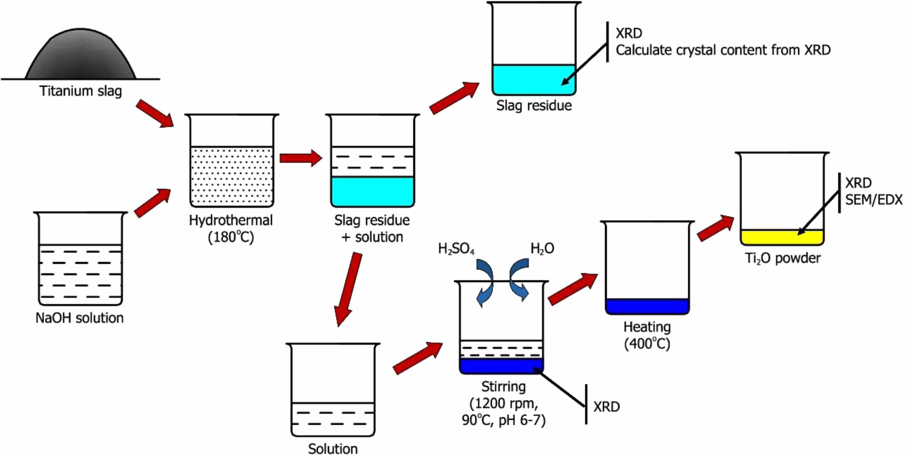
The synthesis of TiO2 from titanium slag involves three distinct stages. The experimental procedure diagram is depicted in Fig. 1.
- Stage 1 – Separation of TiO2 from titanium slag: Titanium slag powder was combined with NaOH in a mass ratio of 1:1.05, and water was added to achieve a NaOH concentration of 5, 10, 15, and 20 M. The mixture undergone stirring at 90 oC for 1 hour, followed by a reaction in a hydrothermal autoclave at 180 oC for 7 hours. The resulting product is filtered to isolate liquid and solid phases. The solid phase was washed with distilled water, and its chemical composition was determined using X-ray Diffraction methods to assess TiO2 separation efficiency. The solution was retained for the TiO2 recovery reaction.
- Stage 2 – Precipitation of TiO(OH)2: The solution from the hydrothermal autoclave undergone a reaction with a 50% sulfuric acid solution. An acidic solution was added until the pH reaches 6-7, occurring at 90 oC using a magnetic stirrer at 1200 rpm. Distilled water was added to the mixture at a ratio 3:1 and stirred for 2 hours. The reaction solution was precipitated to obtain TiO(OH)2, followed by washing and filtration using a centrifuge. The formed minerals were identified using the XRD method.
- Stage 3 – Heating to form TiO2 powder: The precipitated powder was subjected to a heat treatment at 400 oC for 2 hours to yield TiO2. Following the heat treatment, the chemical and mineral composition of the resulting TiO2 powder was analyzed using X-ray Diffraction, X-ray Fluorescence, Scanning Electron Microscopy, and Energy Dispersive X-ray Spectroscopy methods. These techniques allowed for the detailed examination of the crystalline structure, elemental composition, and morphology of the TiO2 product.
Analysis method
The particle size distribution of the raw materials was analyzed using the laser method, employing Horiba’s LA-920 laser analyzer and adhering to analytical conditions outlined by ASTM D4464.
X-ray diffraction (XRD) was employed for mineral identification of the products, utilizing the Brucker D2 PHARSER XRD analyzer. The analysis conditions included a scan range from 10 to 75o, a scan step of 0.02, and operating in mode C.
X-ray fluorescence (XRF) analysis was conducted using the ARL ADVANT’X analyzer from Thermo to determine the chemical composition of the samples.
The scanning electron microscopy method (SEM) combined with energy-dispersive X-ray spectroscopy (EDX) was employed to examine the microstructure and elemental composition distribution on the sample surface. The analytical instrument used for this purpose is the Jeol JSM-IT 200.
These advanced analytical techniques collectively contribute to understanding the material’s physical, chemical, and structural characteristics under investigation.
|
Fig. 1 The experimental procedure diagram |

Separation of TiO2 from titanium slag
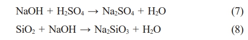
After hydrothermal treatment at 180 oC for 7 hours with a NaOH solution, the residual titanium slag underwent washing and XRD analysis to assess the remaining components post-reaction. The XRD patterns of the residual samples are depicted in Fig. 2. The outcomes indicate that the samples exhibit similar XRD patterns, with predominant minerals identified as FeTiO3, Fe2TiO5, and TiO2. Specifically, FeTiO3 is discerned at diffraction positions 32.2o, 36.1o, 40.3o, 48.1o, 64.5o [22, 23]. Fe2TiO5 is characterized at diffraction positions 17.6o, 17.9o, 25.2o, 32.5o, 36.9o, 40.7o, 48.9o [22]. TiO2 is evident at diffraction positions 25.2o, 36.1o, 49.9o, 55o [22, 24, 25]. In Fig. 2, the XRD patterns depicting the mineral composition of the samples exhibit similarities across NaOH concentrations of 10 M, 15 M, and 20 M. During this experiment, the solid portion remaining in the autoclave after washing was subjected to XRD analysis. Consequently, their mineral composition remains similar, including FeTiO2, Fe2TiO5, and TiO2. These minerals are inherent constituents of the raw titanium slag material and have not undergone dissolution by NaOH within the hydrothermal environment. Titanium slag is a byproduct of the recovery of hematite from ilmenite ore. Its mineral composition has been shown in the study of H. T. Ngon et al. [26] Nevertheless, Fig. 2 reveals that the relative intensity and the number of peaks within the FeTiO3, Fe2TiO5, and TiO2 ranges diminish with increasing NaOH concentration. This shows the significant impact of NaOH concentration on the efficacy of TiO2 recovery in titanium slag.
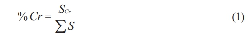
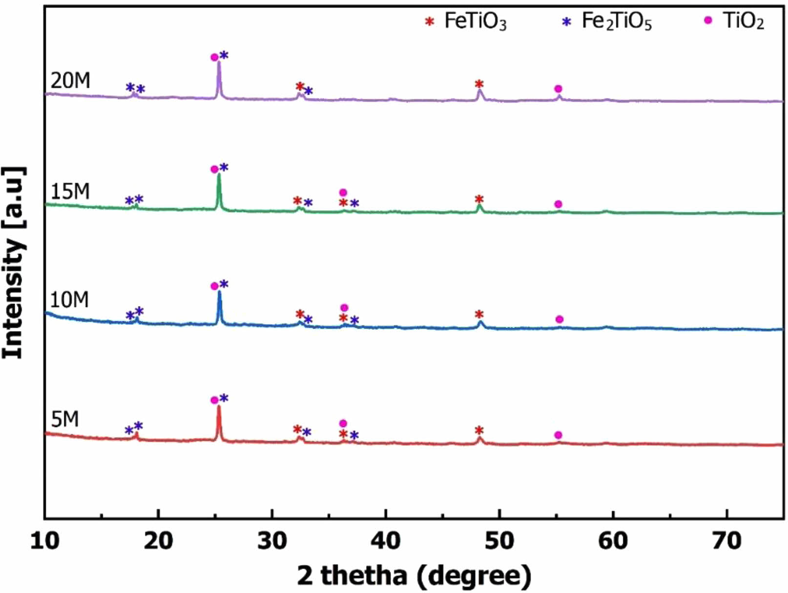
Additionally, the mineral content of FeTiO3, Fe2TiO5, and TiO2 remaining in the slag was calculated based on formula (1) using the XRD patterns. Here, %Cr represents the remaining content of FeTiO3, Fe2TiO5, and TiO2 minerals in the residue; SCr is the peak area of the minerals FeTiO3, Fe2TiO5, and TiO2 on the XRD patterns; ΣS is the total area of the XRD patterns. The results of calculating the crystalline content are depicted in Fig. 3. This calculation further complements the observations from the XRD patterns in Fig. 2. As the NaOH concentration increased, the strong alkali enhanced TiO2 solubility in the autoclaved environment. Consequently, the content of titanium salts of iron and titanium in the slag decreased with the rising NaOH concentration. The slope of the crystal content graph in various sections indicates that increasing the NaOH concentration to 10 M enhances the ability to dissolve TiO2 in the slag. However, if the NaOH concentration is further increased (15 M and 20 M), TiO2 continues to dissolve, but the dissolution rate experiences a significant decline.
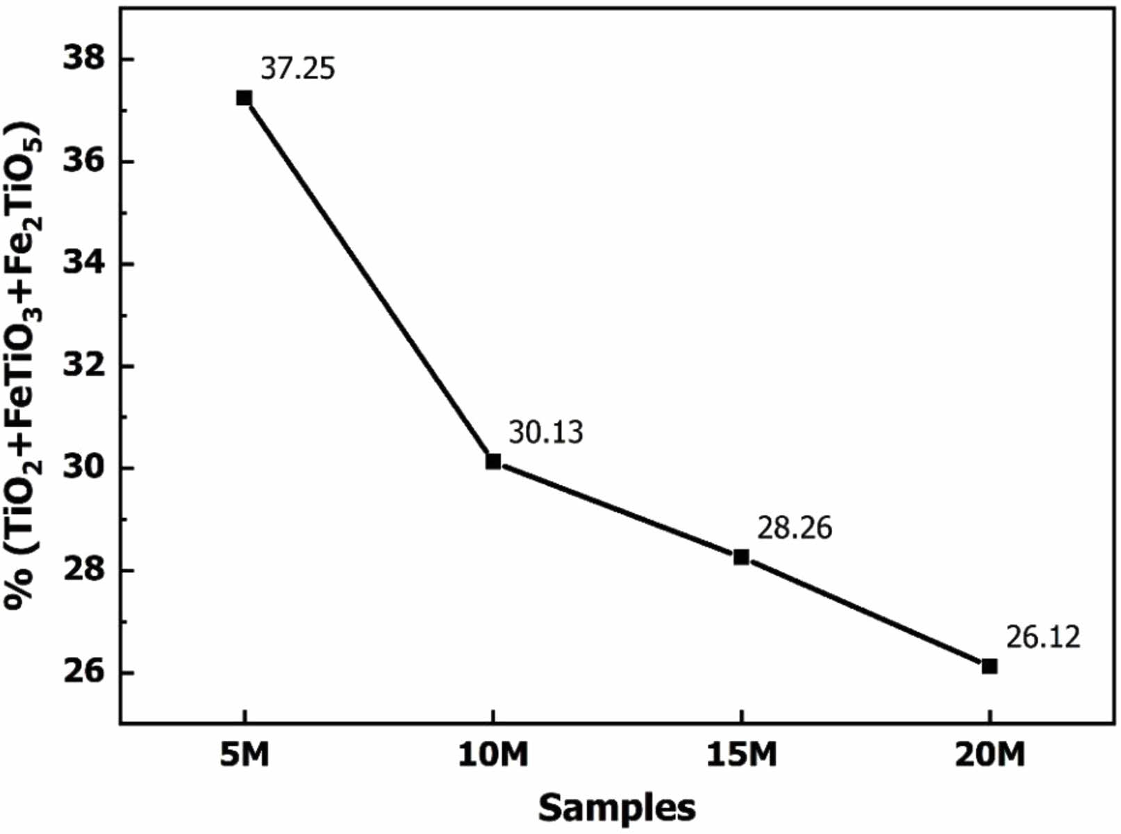
The reactivity of the NaOH solution was assessed through the microstructure images of the slag particles post-reaction. Fig. 4 presents SEM images of slag samples reacted to NaOH solutions at 5 M, 10 M, 15 M, and 20 M concentrations. The SEM results reveal that the slag particles in the 5 M sample maintain a sharp shape. This suggests that the 5 M NaOH solution, with a relatively low reactant concentration, exhibits a limited ability to dissolve the slag particles. Conversely, in samples treated with 10 M, 15 M, and 20 M NaOH solutions, the sharp shape of the slag particles disappeared. Instead, the particles become rounded, with a gel layer covering their exterior. These results indicate that NaOH actively participates in the dissolution of slag particles at these concentrations. The SEM image findings align with the observations derived from the results presented in Fig. 2 and Fig. 3, providing a consistent view of the impact of NaOH concentration on slag dissolution.
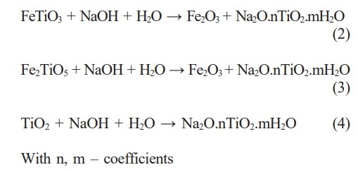
The results of the XRD patterns, calculation of the amount of minerals in the residue, and SEM microstructure images show that as the NaOH concentration increases, the dissolution reaction of TiO2 in the slag increases. Therefore, the residue’s content of FeTiO3, Fe2TiO5, and TiO2 minerals decreased. Accordingly, the intensity of their peaks on the XRD patterns in the residue decreased. The existence of the above minerals also shows that the dissolution of TiO2 in the slag is incomplete, but there was still a certain amount of TiO2 in the slag. The dissolution process of TiO2 in slag can be described by the reaction (2-3). The main product of the dissolution process was Na2O.nTiO2.mH2O. Na2O.nTiO2.mH2O has dissolved into the solution after the reaction. However, using strong alkali to dissolve TiO2 would also potentially contain impurities.
Precipitation of TiO(OH)2
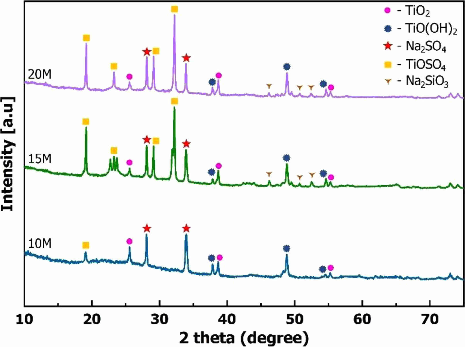
Following the autoclaving reaction, the solution containing Na2O.nTiO2.mH2O was neutralized alkalinity with a sulfuric acid solution and subsequently crystallized in distilled water. The resulting post-crystallized powder was dried and subjected to XRD analysis to identify the mineral composition formed. Fig. 5 presents the mineral composition analysis results for samples treated with 10 M, 15 M, and 20 M NaOH solutions. In the case of sample 5 M, only a minimal percentage of crystalline powder was obtained, indicating that the 5 M NaOH solution concentration is inadequate for the TiO2 dissolution reaction. This finding aligns with the SEM image of slag particles after the reaction of sample 5 M presented in Fig. 4. Therefore, further investigation of this sample was not pursued.
Fig. 5illustrates that the mineral composition of the post-crystallization samples includes TiO(OH)2 and TiO2. TiO(OH)2 is the product of the crystallization of Na2O.nTiO2.mH2O salt in distilled water, and it manifests at the diffraction positions 37.9o, 48.8°, 54.6o [26]. This mineral is also the desired product in separating TiO2 from titanium slag, as TiO(OH)2 undergoes conversion into TiO2 when heated to high temperatures. Alongside TiO(OH)2, crystalline TiO2 is observed in the XRD patterns after crystallization, appearing at diffraction positions 25.6o, 38.7o, 55.2o [22, 24]. In theory, TiO2 will not form after crystallization from Na2O.nTiO2.mH2O solution. Instead, TiO2 is identified as a component in the original titanium slag material, as evidenced in the XRD results in Fig. 2. The occurrence of TiO2 in the Na2O.nTiO2.mH2O solution after hydrothermal autoclaving indicates its retention in the samples following the crystallization of TiO(OH)2 from the solution. The crystallization process of TiO(OH)2 can be elucidated through chemical reactions (5, 6).
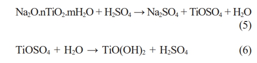
In addition to TiO(OH)2 and TiO2, other impurities present in the samples after crystallization include Na2SO4, TiOSO4, and Na2SiO3. Identifying these impurities is based on specific diffraction positions in the XRD patterns. Na2SO4 is represented by diffraction positions 28.1o, 33.9o [27]. TiOSO4 is characterized at diffraction positions 19.1o, 23.2o, 29.1o, 32.2o [28]. These sulfate salts are formed through alkaline neutralization in a post-hydrothermal solution with a sulfuric acid solution. Na2SO4 is generated from the reaction (5, 7), while TiOSO4 results from its formation during the reaction with sulfuric acid (5) and incomplete hydrolysis from the reaction (6). Meanwhile, Na2SiO3 is produced through the dissolution of SiO2 in slag by a strong alkaline solution, as described in the reaction (8). Na2SiO3 appears at diffraction positions 46.2o, 50.7o, 52.5o [29].
The results in Fig. 5 also indicate that, at concentrations of 15 M and 20 M NaOH solutions, the products obtained after the process contain more undesired compounds than the sample using 10 M. This is evident from more distinct peaks on the XRD patterns of 15 M and 20 M samples than sample 10 M. Utilizing a high-concentration alkaline solution can enhance the solubility of TiO2 in slag. However, this increased solubility also results in the slag’s dissolution of other chemical elements, necessitating more sulfuric acid to neutralize the alkaline solution. Consequence, impurities such as Na2SO4, TiOSO4, and Na2SiO3 appear in the powder samples after crystallization. Na2SiO3 is the resultant compound generated during alkalinization, while Na2SO4 and TiOSO4 are the byproducts of hydrolysis. Among them, Na2SO4 and Na2SiO3 are soluble in water and can be eliminated through dynamic washing techniques. These impurities indicate the need for further consideration and potentially additional steps in processing the crystallized samples to achieve desired purity levels.
Heating to form TiO2 powder
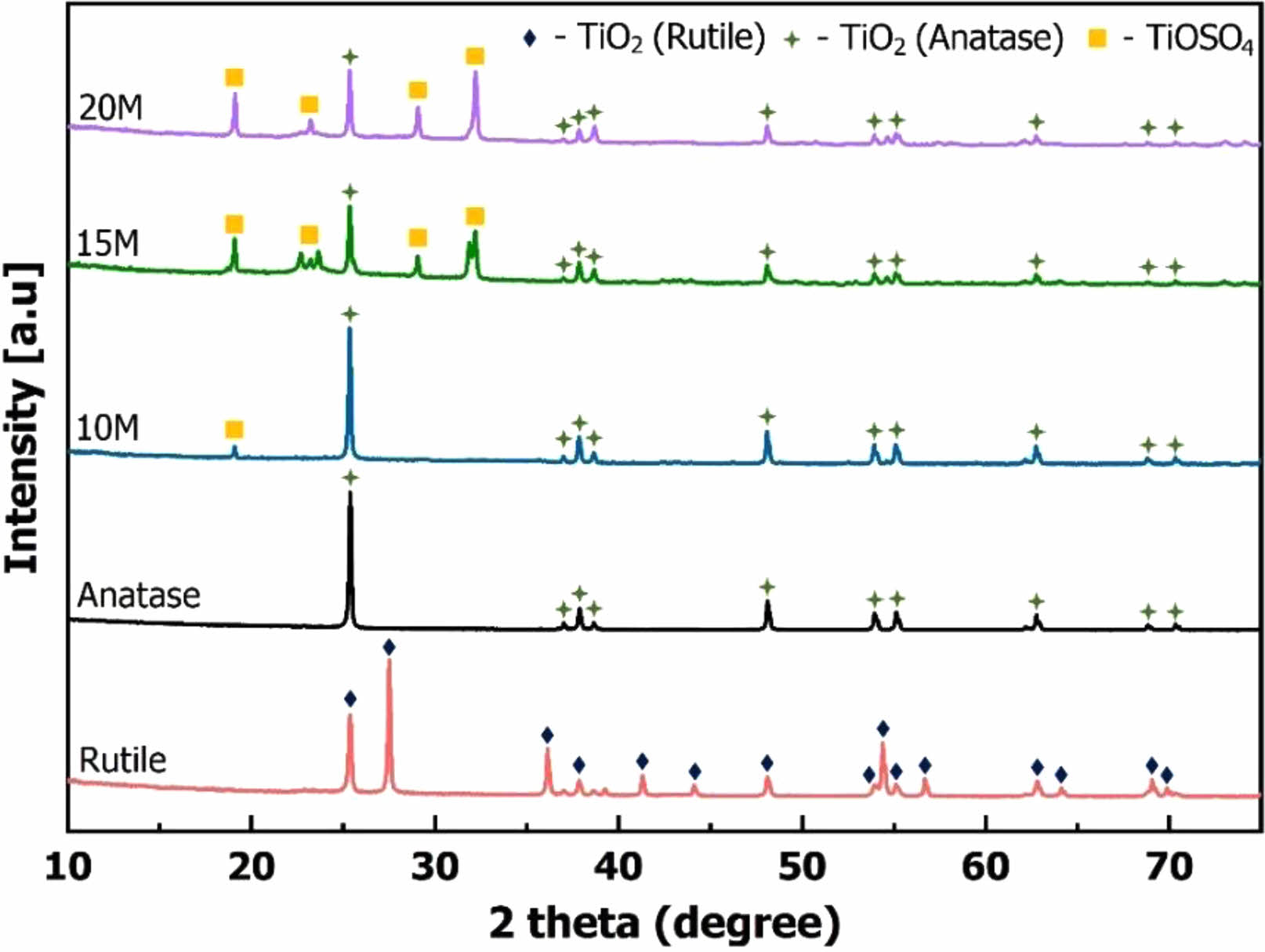
The powder samples were washed with distilled water following crystallization to eliminate soluble salts. Subsequently, the samples were calcined at 400 oC to produce TiO2 powder. The calcined TiO2 powder samples were then analyzed by XRD to observe the mineral composition formed. Fig. 6 illustrates the XRD analysis results of the samples post-calcination. In Fig. 6, the rutile and anatase XRD patterns correspond to the respective commercial samples. These reference samples are employed to indicate the allotropes of TiO2 formed after the calcination of TiO(OH)2 powder following crystallization.
The results from Fig. 6 reveal that the mineral compositions of 10 M, 15 M, and 20 M samples are similar. After calcination, anatase and TiOSO4 salt minerals are evident in the powder samples. Anatase is a mineral formed through the pyrolysis of TiO(OH)2 at 400 oC. The elevated temperature induces the separation of chemical water in TiO(OH)2, leading to the formation of TiO2 according to the reaction (9). Anatase is observable in Fig. 6 at diffraction positions 25.4o, 37.1o, 37.9o, 38.6o, 48.1o, 53.9o, 55.1o, 62.8o, 68.8o, 70.3o [30, 32]. In addition to TiO2, the impurity TiOSO4 persists in the samples post-calcination. The presence of TiOSO4 suggests that this compound is challenging to dissolve in water during the washing process. TiOSO4 is notably prominent in the 15 M and 20 M samples, while it is only observed at the peak of 19.1o in the XRD pattern of the 10 M sample. However, TiOSO4 can be eliminated by the hydrolysis reaction (6). The efficiency of reaction (6) largely depends on factors such as time, temperature, and mixing speed. Therefore, further investigations into the conditions for TiOSO4 hydrolysis reaction can be conducted to remove this impurity.

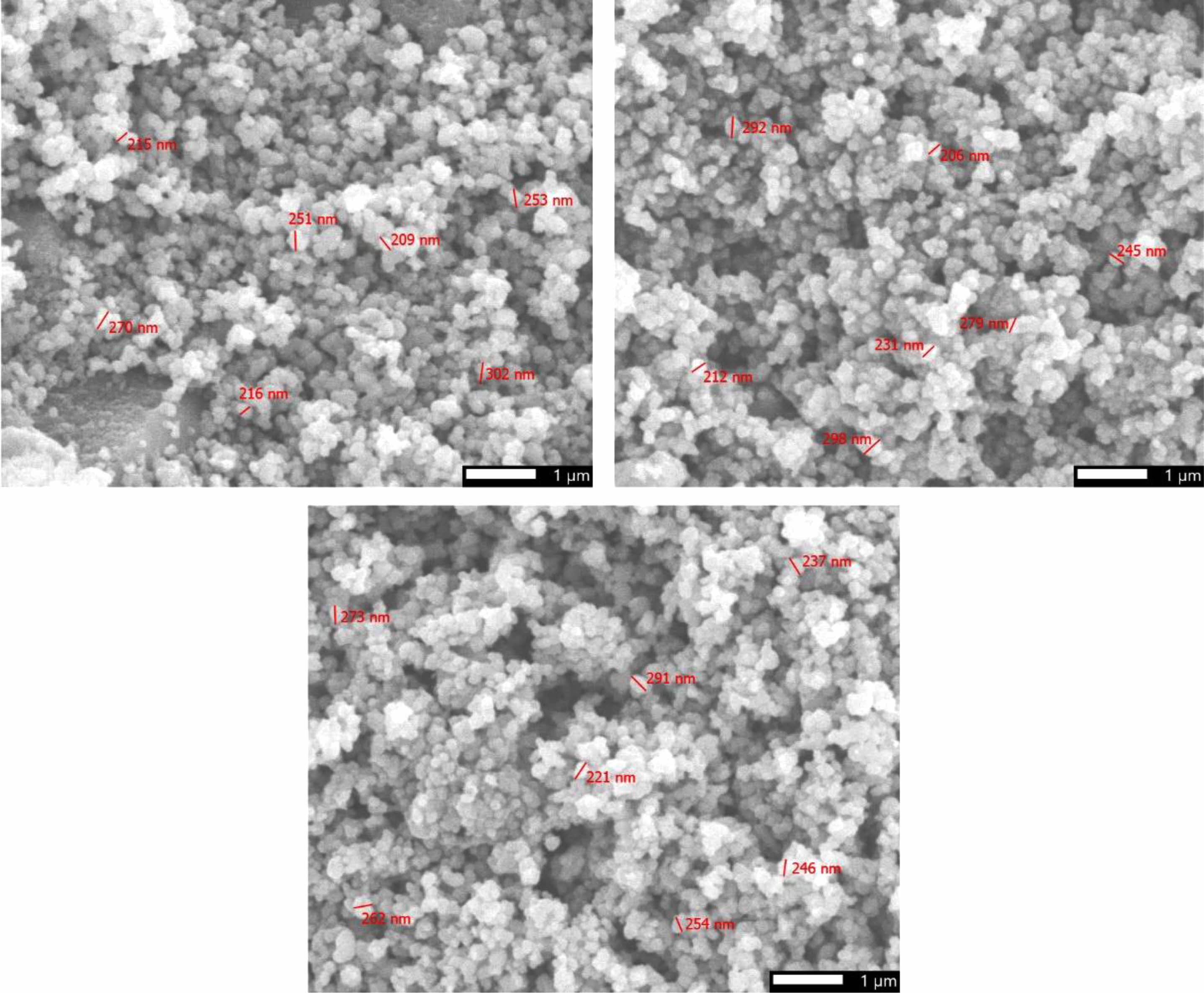
The morphological characteristics of anatase were examined through scanning electron microscopy (SEM). The SEM image results, as illustrated in Fig. 7, portray the features of the synthesized anatase powders. Notably, these images demonstrate a uniformity in the shapes of the TiO2 powders, showcasing a prevailing spherical morphology with particle sizes falling within the range of 200 to 300 nanometers. The outcomes of the SEM analysis underscore that the method involving alkaline dissolution in a hydrothermal environment is conducive to the fabrication of anatase at the nanoscale. The SEM analysis reveals nano-sized TiO2 particles with a uniform spherical morphology. TiO2 is a chemical compound exhibiting photocatalytic properties. Owing to its photocatalytic capability, TiO2 can degrade organic compounds and exhibit antibacterial properties.
Nevertheless, TiO2 possesses a relatively wide band gap energy, ranging from 3.0 to 3.8 eV, depending on its allotropes (including anatase, rutile, and brookite) [33]. Due to its considerable bandgap energy, TiO2 is typically activated by light in the ultraviolet region. Nano-sized TiO2 particles in Fig. 7 contribute to an increased surface area, enhancing their light absorption capacity and participation in photocatalytic reactions. Numerous studies have substantiated this phenomenon by examining the band gap energy of TiO2 [34]. It has been demonstrated that the band gap energy of TiO2 decreases when in nano form. This reduction in the band gap facilitates the activation of photocatalytic effects using only the visible light spectrum [35]. In essence, the nano-sized anatase particles, with their distinctive morphological and optical properties, not only elevate the material’s surface area but also amplify its photoresponsive characteristics, thereby augmenting its effectiveness in decomposing organic matter and eradicating bacteria.
In addition to morphology observations, the chemical composition of the TiO2 powder were analyzed using EDX method. Fig. 8 illustrates the chemical composition distribution map, showing how elements are distributed within the synthesized material.
The chemical composition analysis results indicate that the elemental components of the samples are oxygen, sulfur, and titanium. These elements constitute the TiO2 and TiOSO4 minerals. The composition ratios in Fig. 8 further demonstrate that the 10 M sample has the highest titanium content at 63.66%. Titanium content gradually decreases with an increase in NaOH concentration, reaching the lowest content of 39.33% in the 20 M sample. The reduction in titanium content is attributed to the increased presence of impurities when a larger amount of sulfuric acid solution is required to neutralize NaOH. This is supported by the observation that the sulfur content of the samples increases with higher NaOH concentration in the solution, with values of 1.09% in the 10 M sample, 9.62% in the 15 M sample, and 11.57% in the 20 M sample. These results reinforce the conclusions drawn from the XRD patterns in Fig. 6. While utilizing high concentrations of alkali can yield a substantial amount of TiO2, it also introduces impurities that prove challenging to remove in the final product. The higher the NaOH concentration, the more impurities are present in the product.
|
Fig. 2 The XRD patterns of titanium slag residues. |
|
Fig. 3 The crystal content of TiO2, FeTiO3, and Fe2TiO3 (%wt.). |
|
Fig. 4 The SEM images of slag samples reacted to NaOH solutions. |
|
Fig. 5 The XRD patterns of TiO(OH)2 powders |
|
Fig. 6 The XRD patterns of TiO2 powders |
|
Fig. 7 The microstructure image of TiO2 powders. |

|
Fig. 8 The elemental composition of TiO2 powders. |
In this study, TiO2 was synthesized from titanium slag using the alkaline dissolution method in a hydrothermal device. The results demonstrate that the concentration of NaOH used significantly influences the properties of the resulting TiO2 powder. Quantitative crystallinity results from XRD patterns of samples after hydrothermal autoclaving reveal that increased NaOH concentration enhances the solubility of TiO2 in slag. However, a NaOH concentration of 5 M proves insufficient to dissolve the necessary amount of TiO2. Higher NaOH concentrations are accompanied by increased solubility of other chemical compounds and the augmented requirement for a sulfuric acid solution to neutralize NaOH after the hydrothermal reaction. The XRD and EDX analyses of post-crystallization and post-calcination samples indicate impurities such as Na2SO4, Na2SiO3, and TiOSO4. While Na2SO4 and Na2SiO3 can be removed after washing, TiOSO4 persists in the final TiO2 product. TiOSO4 can be eliminated through a hydrolysis reaction. Additional research on this reaction can be conducted to determine the optimal conditions for removing TiOSO4 impurities. Considering all factors, a NaOH concentration of 10 M is deemed appropriate for effectively separating TiO2 from titanium slag. Furthermore, SEM microstructural analysis results reveal that the grain size of TiO2 falls within the range of 200-300 nm. TiO2 particles at the nano level increase the surface area of the resulting TiO2 powder. Coupled with the anatase form identified from XRD patterns, TiO2 can be utilized as a photocatalytic, bactericidal, and environmental treatment material.
We acknowledge the Ho Chi Minh City University of Technology (HCMUT), VNU-HCM for supporting this study.
- 1. M.J. Gázquez, J.P. Bolívar, R. García-Tenorio and F. Vaca, Mater. Sci. Appl. 5 (2014) 441-458.
-

- 2. M. Li, Y. Geng, G. Liu, Z. Gao, X. Rui, and S. Xiao, Resour. Conserv. Recycl. 180 (2022) 106166.
-
- 3. H. Yin, Y. Wada, T. Katamura, S. Kambem, S. Murasawa, H. Mori, T. Sakata, and S. Yanagida, J. Mater. Chem. 11 (2001) 1694-1703.
-
- 4. S. Sathiyanarayanan, S.S. Azim, and G. Venkatachari, Prog. Org. Coat. 59 (2007) 291-296.
-
- 5. J.-K. Park, J.-K. Kim, and H.-K. Kim, J. Mater. Process. Technol. 186 (2007) 367-369.
-
- 6. J.H. Braun, A. Baidins, and R.E. Marganski, Prog. Org. Coat. 20 (1992) 105-138.
-
- 7. S. Teixeira and A.M. Bernardin, Dyes Pigm. 80 (2009) 292-296.
-
- 8. A. Ashery, ECS J. Solid State Sci. Technol. 11 (2022) 073008.
-
- 9. W. Yang, Y. Yu, M.B. Starr, X. Yin, Z. Li, A. Kvit, S. Wang, P. Zhao, and X. Wang, Nano Lett. 15 (2015) 7574-7580.
-
- 10. M. Chauhan and V.K. Singh, J. Opt. 52 (2023) 1-11.
-
- 11. Y. Tong, Q. Wang, X. Liu, E. Mei, X. Liang, and W. Xiang, Chem. Eng. J. 429 (2022) 132391.
-
- 12. Z. Li, S. Wang, J. Wu, and W. Zhou, Renewable Sustainable Energy Rev. 156 (2022) 111980.
-
- 13. G.S. Leea, S.M. Koo, and J.W. Yoo, J. Ceram. Process. Res. 13 (2012) 300-303.
- 14. A. Adipuri, Y. Li, G. Zhang, and O. Ostrovski, Int. J. Miner. Process. 100 (2011) 166-171.
-
- 15. K. Zhu, X. Ren, H. Li, and Q. Wei, Sep. Purif. Technol. 257 (2021) 117897.
-
- 16. G. Stovpchenko, L. Lisova, L. Medovar, and I. Goncharov, Mater. Sci. 58 (2023) 494-504.
-
- 17. P. Gordienko, V. Dostovalov, and E. Pashnina, Solid State Phenom. 265 (2017) 542-547.
-
- 18. J. Chen, S. Guo, M. Omran, L. Gao, H. Zheng, and G. Chen, Adv. Powder Technol. 33 (2022) 103549.
-
- 19. Y.F. Han, T.C. Sun, J. Li, L.N. Wang, T.Y. Xue, and T. Qi, Adv. Mater. Res. 418 (2012) 387-392.
-
- 20. D. Wang, J. Chu, Y. Liu, J. Li, T. Xue, W. Wang, and T. Qi, Ind. Eng. Chem. Res. 52 (2013) 15756-15762.
-
- 21. S.D. Yoon, J.H. Lee, and Y.H. Yum, J. Ceram. Process. Res. 17 (2016) 91-96.
-
- 22. W. Lv, X. Lv, J. Xiang, J. Wang, X. Lv, C. Bai, and B. Song, Int. J. Miner. Process. 169 (2017) 176-184.
-
- 23. H. Salehi, S. Seim, L. Kolbeinsen, and J. Safarian, Min., Metall., Explor. 38 (2021) 1167-1173.
-
- 24. K.D.T. Kien, N.V.U. Nhi, H.N. Minh, and D.Q. Minh, J. Ceram. Process. Res. 23 (2022) 350-355.
-
- 25. P. Pookmanee and S. Phanichphant, J. Ceram. Process. Res. 10 (2009) 167-170.
-
- 26. H.T. Ngon, P.D. Tuan, and K.D.T. Kien, Ceram. -Silik. 67 (2023) 328-333.
-
- 27. G. Liu, M. Li, and Y. Zhou, Oxid. Met. 66 (2006) 115-125.
-
- 28. L. Omar, R. Benaissa, G. Vincent, M. Francis, P. Gaël, and D. Lahcen, J. Miner. Mater. Charact. Eng. 10 (2022) 254-274.
-
- 29. L. Wang, A.K. Tieu, H. Zhu, S. Cui, G. Deng, G. Hai, and J. Yang, J. Phys. Chem. C 123 (2019) 14468-14479.
-
- 30. D. Kim, S. Kang, and K. Kim, J. Ceram. Process. Res. 24 (2023) 807-815.
-
- 31. H. Sutrisno and Sunarto, J. Ceram. Process. Res. 18 (2017) 378-384.
-
- 32. M. Ali, J. Ceram. Process. Res. 15 (2014) 290-293.
-
- 33. A. Maddu, R. Purwati, and M. Kurniati, J. Ceram. Process. Res. 17 (2016) 360-364.
-
- 34. B.S. Avinash, V.S. Chaturmukha, H.S. Jayanna, C.S. Naveen, M.P. Rajeeve, B.M. Harish, S. Suresh, and A.R. Lamani, AIP Conf. Proc. 1728 (2016) 020426.
-
- 35. K.D.T. Kien, D.Q. Minh, H.N. Minh, and N.V.U. Nhi, Ceram. -Silik. 67 (2023) 58-63.
-
 This Article
-
2024; 25(3): 375-383
Published on Jun 30, 2024
- 10.36410/jcpr.2024.25.3.375
- Received on Feb 29, 2024
- Revised on Apr 15, 2024
- Accepted on Apr 23, 2024
Services
- Abstract
introduction
experimental
results and discussion
conclusion
- Acknowledgements
- References
- Full Text PDF
Shared
Correspondence to
- Hoang Trung Ngona,c, Kieu Do Trung Kienb,c,*
-
aFaculty of Chemical Engineering, Ho Chi Minh City University of Technology (HCMUT), 268 Ly Thuong Kiet street, District 10, Ho Chi Minh City, Vietnam
bFaculty of Materials Technology, Ho Chi Minh City University of Technology (HCMUT), 268 Ly Thuong Kiet street, District 10, Ho Chi Minh City, Vietnam
cVietnam National University Ho Chi Minh City, Linh Trung Ward, Thu Duc City, Ho Chi Minh City, Vietnam
Tel : (84.8) 8 661 320 Fax: (84.8) 8 661 843 E-mail: htngon@hcmut.edu.vn, kieudotrungkien@hcmut.edu.vn - E-mail: htngon@hcmut.edu.vn, kieudotrungkien@hcmut.edu.vn
Clean-Energy Research Institute(CRI), Hanyang University, 222, Wangsimni-ro, Seongdong-gu, Seoul, 04763, Korea
E-mail: jcpr@hanyang.ac.kr