


- Numerical simulation of methanol steam reforming based on Cu/ZnO/Al2O3 via micro-channel reactor for hydrogen production
Weiqiang Konga, Qiuwan Shena,*, Jiadong Liaoa, Ziheng Jianga, Naibao Huangb, Guogang Yanga and Shian Lia
aMarine Engineering College, Dalian Maritime University, Dalian, China
bCollege of Transportation Engineering, Dalian Maritime University, Dalian, ChinaThis article is an open access article distributed under the terms of the Creative Commons Attribution Non-Commercial License (http://creativecommons.org/licenses/by-nc/4.0) which permits unrestricted non-commercial use, distribution, and reproduction in any medium, provided the original work is properly cited.
A three-dimensional numerical model of a methanol steam reforming micro-channel reactor for hydrogen production based on Cu/ZnO/Al2O3 catalyst was established. The effects of different inlet mass flow rate, reaction temperature and steam to carbon ratio (S/C) on the mass change of each component, chemical reaction rate and hydrogen production performance of micro-channel reformer were studied. The results show that with the increase of inlet mass flow rate, the mass fraction of CH3OH at the outlet of reforming channel increases gradually, and the methanol conversion rate decreases gradually. The mass fraction of CO at the outlet of reforming channel decreases gradually, and the CO selectivity decreases gradually. With the increase of reaction temperature, the mass fraction of CH3OH at the outlet of reforming channel decreases gradually, and the methanol conversion rate increases. The mass fraction of CO at the outlet of reforming channel increases rapidly, and the CO selectivity increases rapidly. With the increase of S/C, the methanol conversion rate increased and the CO selectivity decreased. In this study, the influence of reaction conditions on methanol reformer was obtained, and the reasons behind it were clarified, which provided more valuable insights for the operating conditions of hydrogen production from MSR.
Keywords: Methanol steam reforming, Cu/ZnO/Al2O3, Hydrogen production, Mass transport, Micro-channel.
As a green, clean and renewable energy, hydrogen has been widely concerned. PEM fuel cells are considered a potential friendly power generation device as they can generate almost no pollution while generating electricity [1, 2]. With the rapid development of hydrogen fuel cell technology, the use of hydrogen has become more extensive, and its application prospect has become more promising [3-5]. Methanol has a high ratio of hydrogen to carbon (4 : 1), exists as a liquid at normal temperature and pressure, and can produce hydrogen with water at a relatively low temperature (150-350 ℃), so it is one of the best choices for hydrogen production [6-10]. Methanol hydrogen production technology includes four types, namely methanol steam reforming (MSR), methanol decomposition, methanol partial oxidation and methanol auto-thermal reforming [11-13]. Methanol steam reforming is one of the most common reforming technologies, which has been widely used in existing industrial production [14-16]. Micro-channel technology can be used to improve the performance [17]. The methanol steam reforming micro-channel reactor for hydrogen production is a focus of research by many scholars.
Nowadays, many scholars have carried out experimental research on methanol steam reforming for hydrogen production. Peppley et al. [18] used Cu/ZnO/Al2O3 catalyst to carry out methanol steam reforming experiments, and obtained a generally accepted kinetic equation of MSR-MD-WGS three-rate reaction mechanism. Asprey et al. [19] established a relatively perfect kinetic equation of three-rate reaction mechanism by experimental method, which is generally accepted and widely used in the current three-rate equation [20]. Jiang et al. [21] introduced CO into methanol reforming reaction, and found that the hydrogen generation rate did not change obviously. Therefore, it was proposed that the water-gas shift reaction should not be included in the reforming reaction, and MSR reaction should be taken as the main reaction to reflect the reforming hydrogen production process. Mei et al. [22] prepared a new micro-array methanol reforming reactor to improve the hydrogen production performance of the micro-reactor and reduce the preparation cost of catalyst support. The results show that in the micro-array methanol reforming reactor, the temperature and fluid flow rate are more uniform, and the methanol conversion rate and mole fraction of CO are increased. Mei et al. [23] also prepared A-type micro-channel methanol steam reforming reactor. The results show that, compared with the traditional Z-type micro-channel reactor, the mass distribution in the A-type micro-channel reactor is more uniform, and under the same operating conditions, the A-type micro-channel reactor can effectively increase the methanol conversion rate by about 8% and reduce its pressure drop by about 20%. Zhuang et al. [24] designed a new micro-channel reforming reactor with bifurcated inlet and manifold structure, and carried out long-term stability test of its continuous operation for 36 hours. In the long-term test, the methanol conversion rate was continuously higher than 94.04%, and the mole fraction of CO was lower than 1.05%.
The numerical simulation of hydrogen production by methanol steam reforming is also the focus of researchers. By establishing dynamic model and using fluid simulation software, the corresponding data are obtained by computer simulation calculation. Mastalir et al. [25] established a dynamic model based on experimental data, and used this model for numerical simulation analysis, and the results were approximately consistent with the experimental data. Karim et al. [26] established a two-dimensional numerical model to simulate and analyze the heat and mass transfer characteristics in the reforming reactor. Hao et al. [27] studied the effects of structural parameters of reforming reactor and catalyst thickness on methanol reforming process by numerical simulation, and obtained the optimal structural parameters based on their design. Suh et al. [28] carried out numerical simulation analysis on packed bed reforming reactor, mainly analyzing the distribution law of various materials and temperature, and also studying the influence of catalyst and other factors. Tang et al. [29] proposed an on-line methanol reformer system based on waste heat recovery of methanol-diesel dual direct injection engine, designed a new methanol reformer suitable for this engine, and carried out numerical simulation research on it. The results show that the hydrogen production rate and methanol conversion rate are increased by 60.35% and 27.28%, respectively, compared with the initial conditions.
According to the widely accepted and used kinetic equation of MSR-MD-WGS three-rate reaction mechanism, a three-dimensional numerical model of a methanol steam reforming micro-channel reactor for hydrogen production was established through the verification of numerical simulation results. The effects of different inlet mass flow rate, reaction temperature and steam to carbon ratio on the mass change of each component, chemical reaction rate and hydrogen production performance of micro-channel reformer were studied, and the production effect was deeply analyzed. Through this study, we can get the effect of reaction conditions on methanol reformer more intuitively, and clarify the reasons behind it. The results of this study provide more valuable insights for the operating conditions of hydrogen production by methanol steam reforming.
Physical model
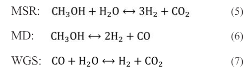
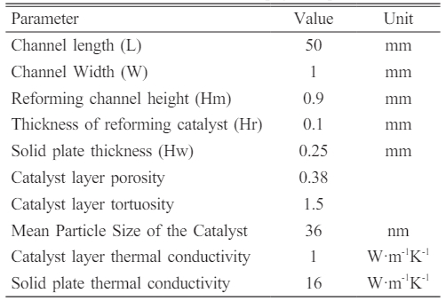
Fig. 1 is a three-dimensional structural diagram of a methanol steam reforming micro-channel reactor for hydrogen production. The calculation domain consists of reforming channel layer, reforming catalytic layer and solid region. The length of reactor is 50 mm, the height of reforming channel is 0.9 mm, the thickness of reforming catalytic layer is 0.1 mm, and the thickness of solid plate in the upper and bottom parts is 0.25 mm. See Table 1 [30] for specific information. In this study, Cu/ZnO/Al2O3 catalyst provided by Peppley et al. [18] was used as reforming catalyst, and stainless steel was used as solid material.
Governing equations
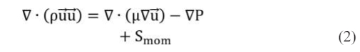
In the simulation study of methanol steam reforming, the governing equations include mass, momentum, energy and species equations, which are expressed as follows:
Mass equation

Momentum equation
Energy equalization

Species Equation

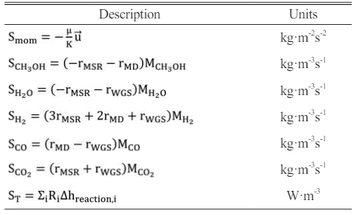
where Smom is the source term in the momentum equation. In the porous layers, the Darcy’s law is adopted; ST is the generated or consumed heat by the corresponding reactions; Si is the source term caused by the chemical reactions in the species equation.
In this study, the reforming catalytic layer undergoes a methanol steam reforming reaction to produce hydrogen. In the methanol steam reforming reaction, three chemical reactions occur, namely methanol steam reforming reaction (MSR), methanol decomposition reaction (MD) and water-gas shift reaction (WGS). The expression for the chemical reaction equation is as follows:
Among them, the methanol steam reforming reaction adopts the kinetic reaction rate equation proposed by Peppley et al., as follows:
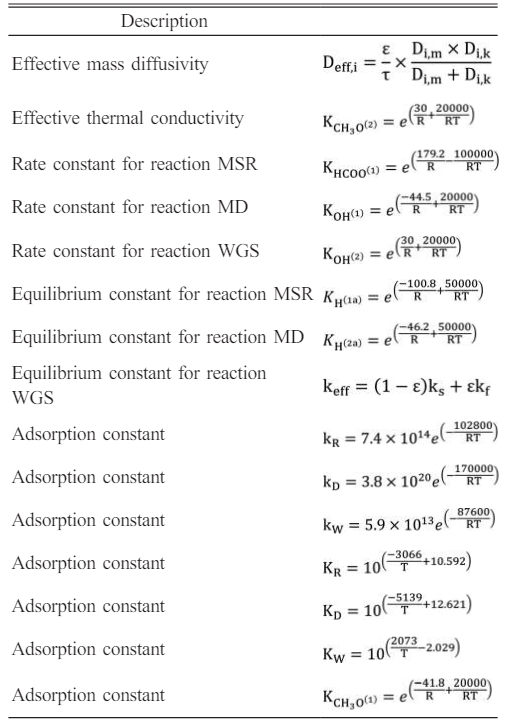
where kj is the rate constant for reaction j, Kj is the equilibrium constant for reaction j, Ki is the adsorption coefficients for surface species i and pi is the partial pressures of the ith species. C TS1, C TS2, C TS1a, and C TS2a are constants which indicate total surface concentrations as reported by Peppley et al.. Sc is the catalyst specific surface area, rb is the bulk density of the catalyst.
The source terms of the governing equations and the parameters in the kinetic rate equations are given in Table 2 and Table 3 [31, 32].
Numerical methods
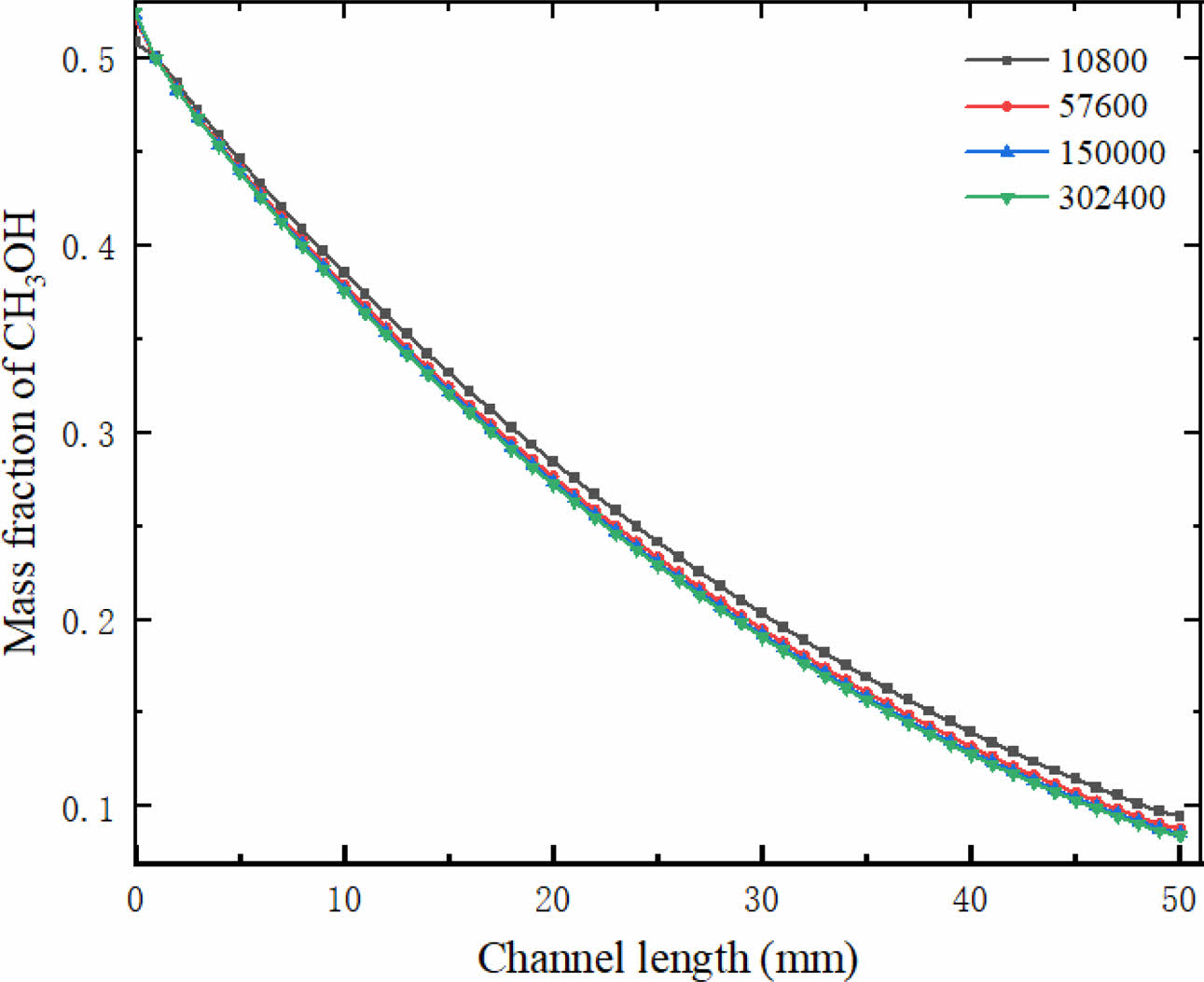
ANSYS FLUENT is a commercial fluid software, which is often used to develop mathematical models. The chemical reaction rate, physical parameters, gas diffusion coefficient and source terms used in this study are all realized by user-defined functions (UDFs). Grid independence is shown in Fig. 2. Four grid systems are used in this study, namely, Grid 1 (10800), Grid 2 (57600), Grid 3 (150000) and Grid 4 (302400). The results show that when the number of grids reaches 150,000, the mass fraction of methanol in the reforming channel hardly changes with the further increase of the number of grids. Therefore, in this simulation work, in order to reduce unnecessary computation, 150,000 grids are selected for numerical simulation.
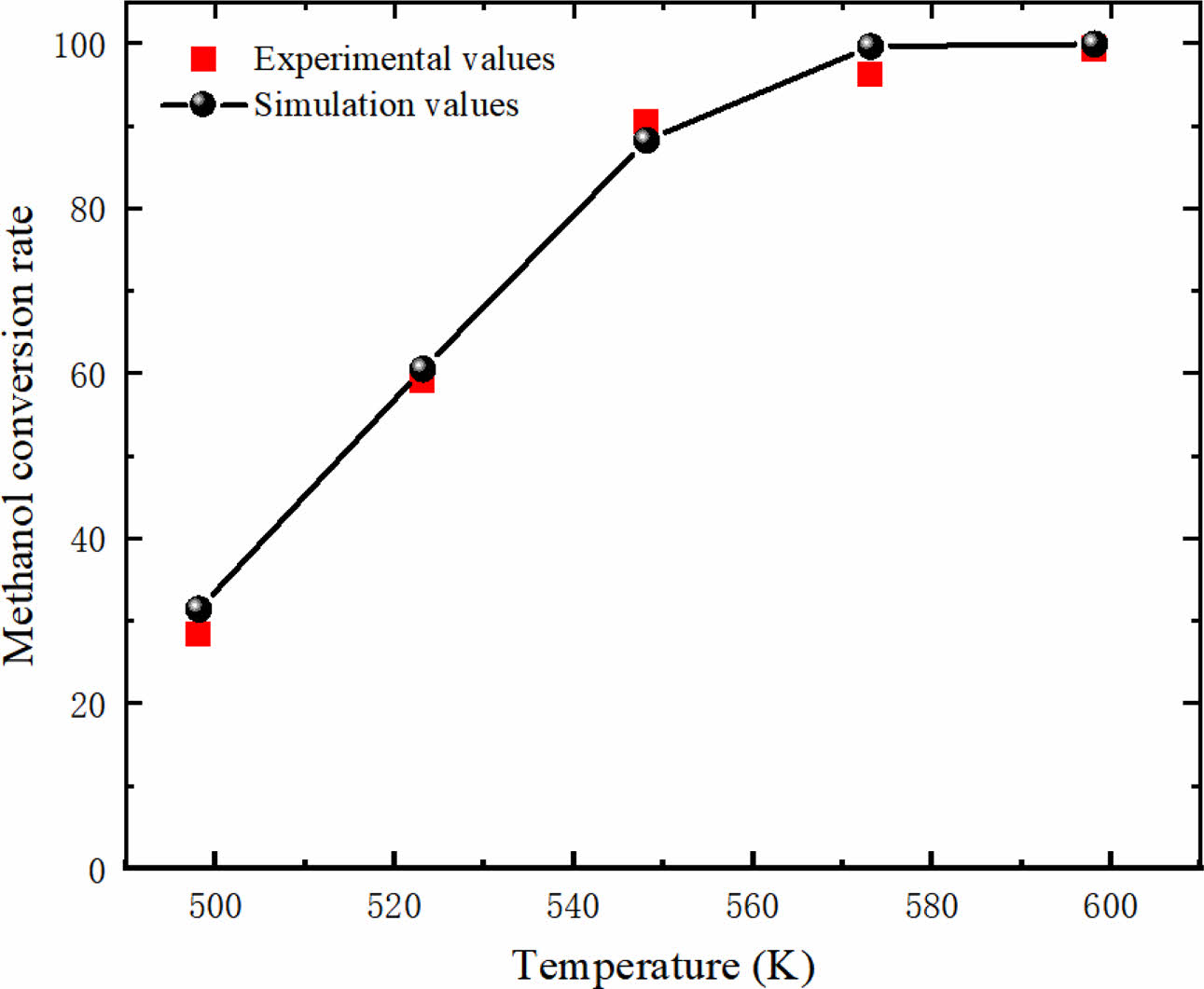
In this study, the accuracy of the mathematical model and dynamic equation used in this study is verified by simulating the experimental and simulation results of Zhuang [33]. As shown in Fig. 3, the predicted results are in good agreement with the experimental results. The results of methanol conversion rate validation by model show that the numerical simulation results using the current mathematical model and kinetic equations are in good agreement with the experimental and simulation results in the literature. Therefore, the kinetic model used in the current research work is effective.
|
Fig. 1 Schematic diagram of the structure of a methanol steam reforming micro-channel reactor for hydrogen production. |
|
Fig. 2 Mesh independence verification. |
|
Fig. 3 Model validation. |
Influence of inlet mass flow rate
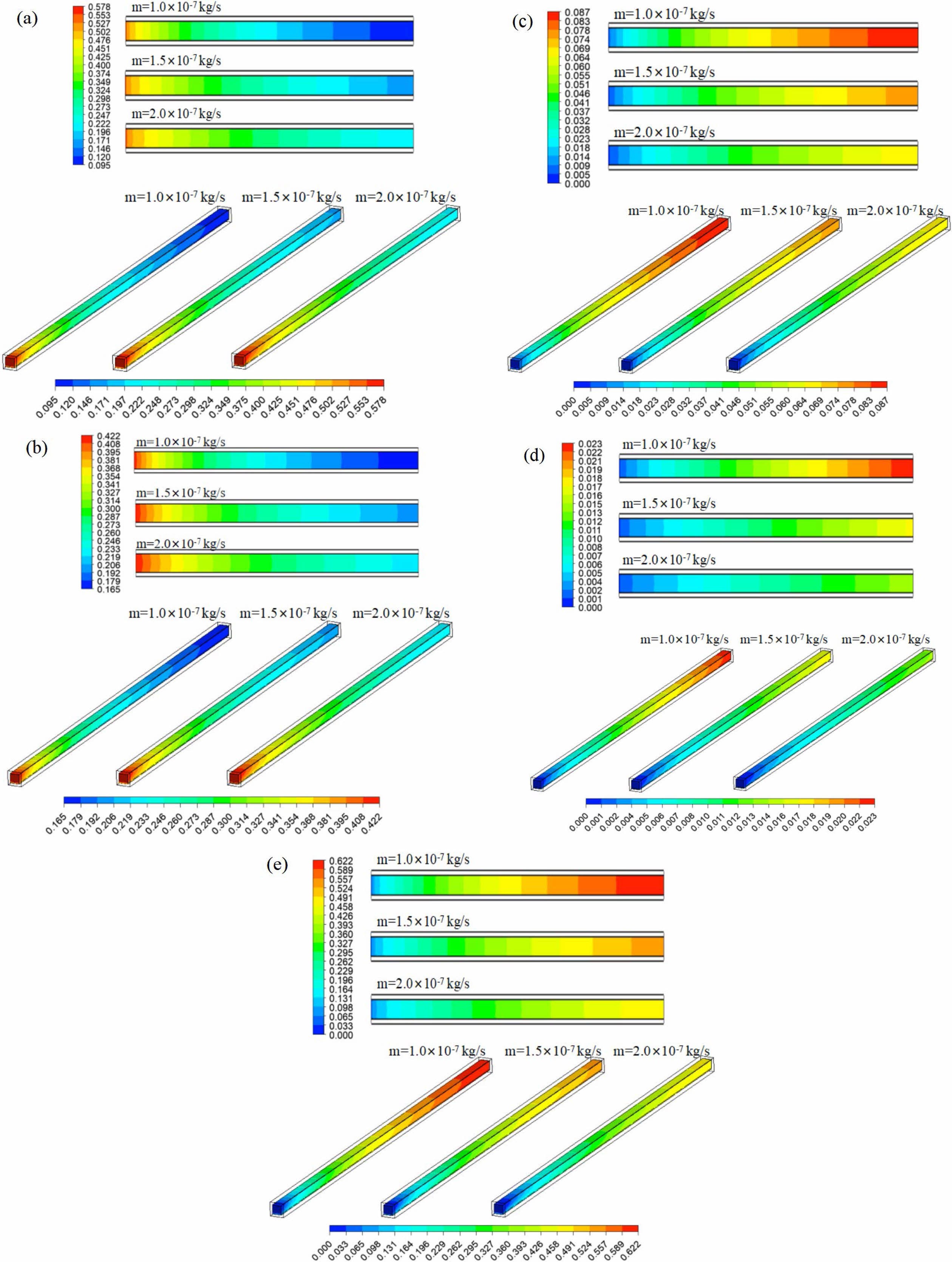
Keep the reaction zone unchanged, and the inlet temperature is equal to the reaction temperature. The influence of inlet mass flow rate (m) on the mass fraction of each reformer gas was investigated at the tentative reaction temperature of 533.15 K and the steam to carbon ratio (S/C) of 1.3. Fig. 4 shows the mass fraction distribution nephogram of each component in the reforming channel under different inlet mass flow rates, in which the two-dimensional plane nephogram is the 1/2 cross-sectional position of the reforming channel height.
It can be seen from the Fig. 4 that with the methanol reforming reaction, the mass fractions of CH3OH and H2O gradually decrease, while the mass fractions of H2, CO and CO2 gradually increase, so CH3OH and H2O are concentrated at the inlet of the reforming channel, while H2, CO and CO2 are concentrated at the outlet of the reforming channel. With the increase of mass flow rate at the inlet of the reforming channel, the consumption of CH3OH and H2O in the reforming channel gradually decreases, while the mass fraction at the outlet of the reforming channel gradually increases. Similarly, with the increase of the inlet mass flow rate of the reforming channel, the amount of H2, CO and CO2 is also gradually reduced, and the mass fraction of them are gradually reduced. This phenomenon occurs because CH3OH and H2O do not react completely in the reforming channel under this working condition, and there are still some residues. If the inlet mass flow rate continues to increase, the amount of reactants per unit time will increase, and the reaction will become more and more incomplete, and a large number of reactants will flow out through the reforming channel without reaction. As a result, the mass fractions of CH3OH and H2O at the outlet of the reforming channel increase, while the mass fractions of H2, CO and CO2 decrease.
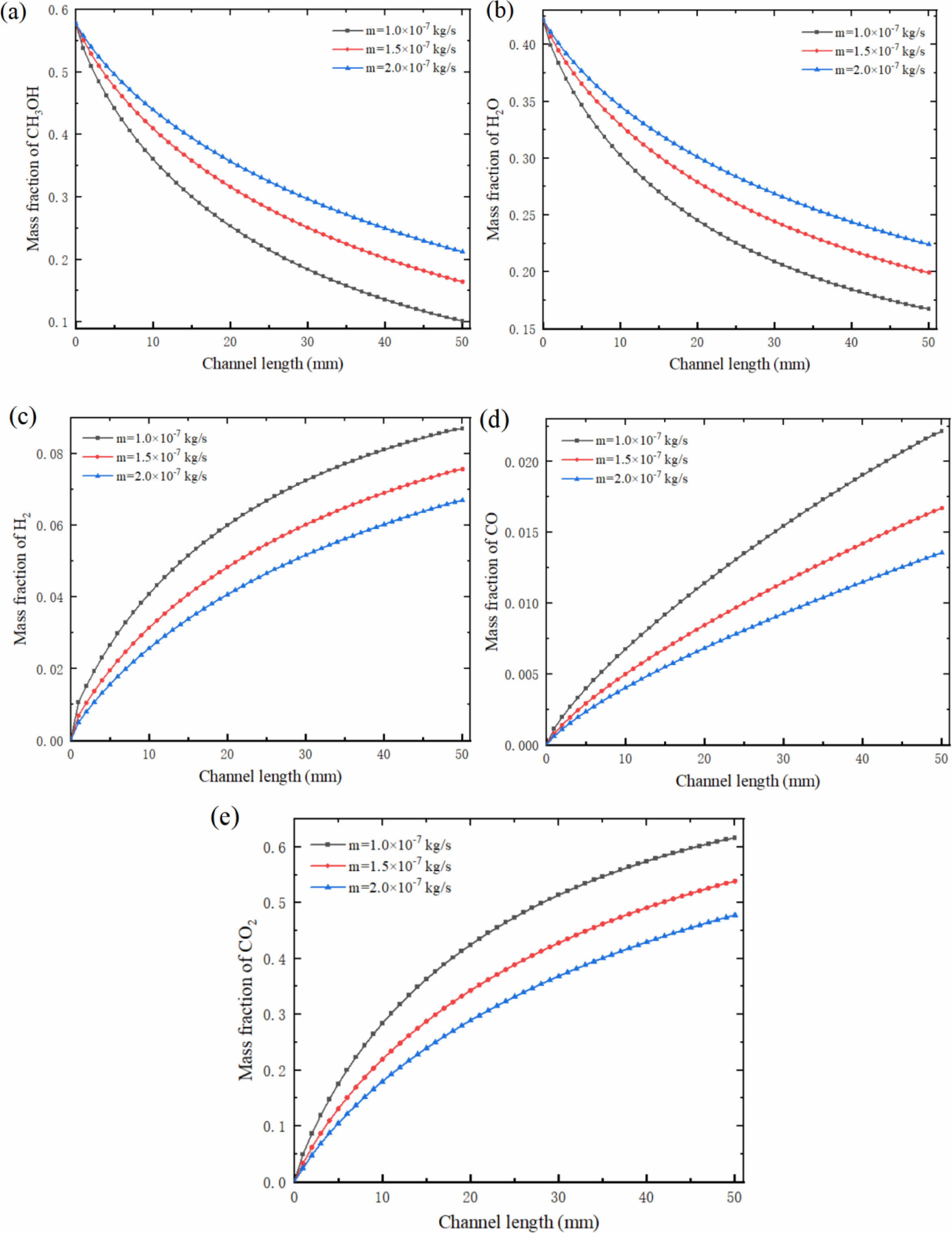
Fig. 5 shows the mass fraction curve of each component at the center of the reforming channel under different inlet mass flow rates. It can be seen from the Fig. 5 that at the mass flow rate of 1.0×10⁻⁷ kg/s, the mass fraction of CH3OH decreases from 0.578 to 0.102; Under these conditions, the mass fraction of H2 is the highest, which is 0.087. The mass fraction of CO is 0.022. At 1.5×10⁻⁷ kg/s and 2.0×10⁻⁷ kg/s, the mass fraction of CH3OH decreased from 0.578 to 0.165 and 0.212 respectively. Under these conditions, the mass fraction of H2 reached 0.076 and 0.067 respectively, and the mass fraction of CO reached 0.017 and 0.014 respectively. In the reforming channel, the consumption rate of CH3OH and H2O is faster at the inlet, while the consumption rate of reactants near the outlet is slower. The formation rate of H2, CO and CO2 has the same trend, the formation rate is faster at the inlet of the reforming channel, and gradually slower near the outlet of the reforming channel. With the increase of inlet mass flow rate, this trend is gradually decreasing, and the change range is also gradually decreasing. It is worth noting that the formation rate of CO is slightly different from that of H2 and CO2, and the formation rate at the inlet and outlet of the whole reforming channel changes little, and keeps a high formation rate almost all the time.
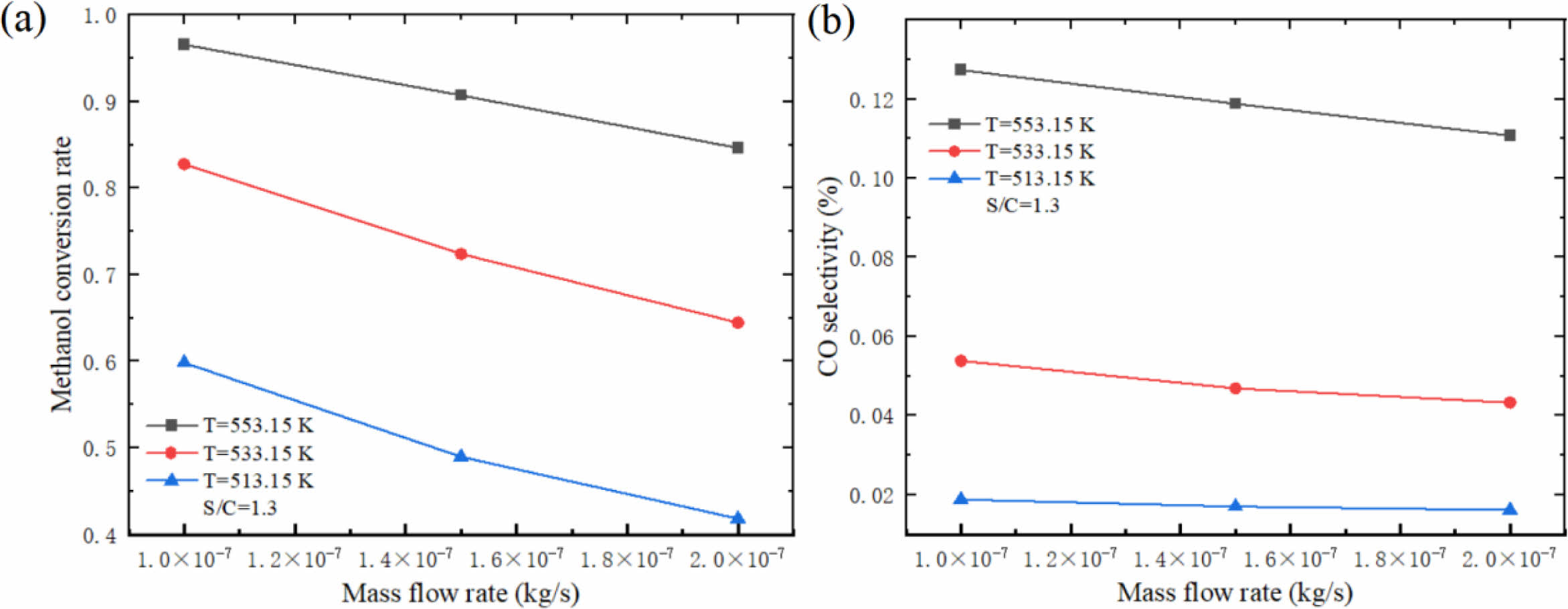
Fig. 6 shows the influence of different inlet mass flow rates on hydrogen production performance of micro-channel reformer. The results show that the methanol conversion rate and CO selectivity decrease with the increase of inlet mass flow rate. This is mainly due to the increase of the inlet mass flow rate, which leads to the increase of the mixed gas flow rate in the catalytic reaction zone, resulting in the decrease of the contact time between the mixed gas and the catalyst, and a large amount of CH3OH has already flowed out of the reforming channel before the reaction, resulting in the decrease of methanol conversion rate and CO selectivity. This indicates that the selection of inlet mass flow should be based on the requirement of methanol conversion rate, and the larger mass flow should be preferred. At this time, the CO content in the product is relatively low, and the CO selectivity is relatively low, which is beneficial to reduce the damage to the fuel cell.
Effect of reaction temperature
The effects of different reaction temperatures on the components of the reformer gas were investigated under the fixed conditions of inlet mass flow rate of 1.5×
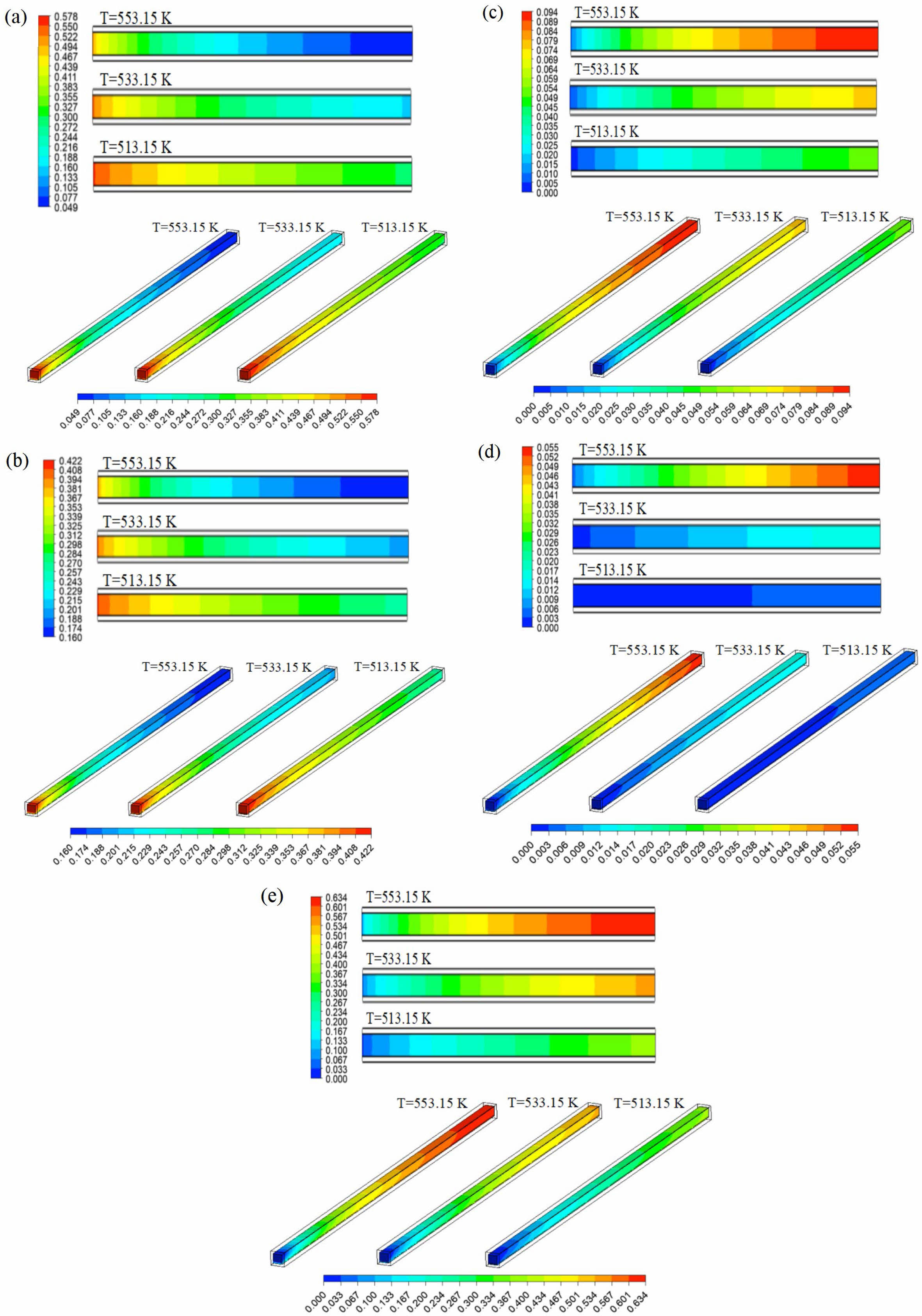
10-7 kg/s and S/C of 1.3. Fig. 7 shows the mass fraction distribution nephogram of each component in the reforming channel at different reaction temperatures, in which the two-dimensional plane nephogram is the 1/2 cross-section position of the reforming channel height. The results show that with the increase of reaction temperature, the consumption of CH3OH and H2O in the reforming channel increases gradually, while the mass fraction at the outlet of the reforming channel decreases gradually. Similarly, with the increase of the reaction temperature in the reforming channel, the amount of H2, CO and CO2 is also gradually increased, and the mass fraction at the outlet of the reforming channel is gradually increased. This phenomenon occurs because the methanol steam reforming reaction is an endothermic reaction, and the increase of temperature promotes the rate of methanol steam reforming reaction and accelerates the reaction, so the increase of temperature can accelerate the consumption of reactants and promote the increase of products.
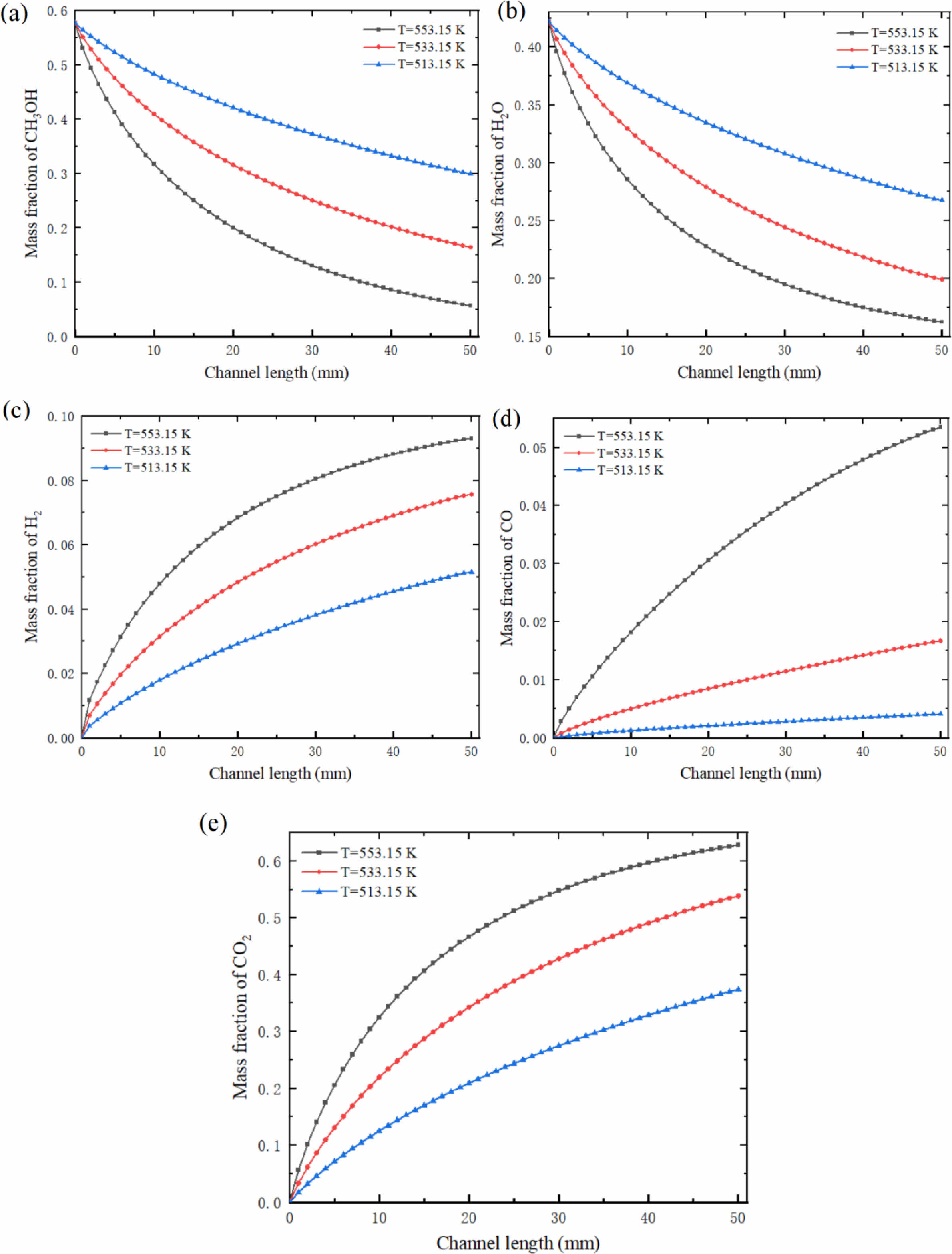
Fig. 8 shows the mass fraction of each component at the center of the reforming channel at different reaction temperatures. At the reaction temperature of 553.15 K, the mass fraction of CH3OH decreased from 0.578 to 0.057; Under these conditions, the mass fraction of H2 is 0.093 and CO is 0.054. At 533.15 K and 513.15 K, the mass fraction of CH3OH decreased from 0.578 to 0.165 and 0.299 respectively. Under these conditions, the mass fraction of H2 reached 0.076 and 0.052 respectively, and the mass fraction of CO reached 0.017 and 0.004 respectively. Similarly, in the reforming channel, the consumption rate of CH3OH and H2O is faster at the inlet, while the consumption rate of reactants near the outlet is slower. The formation rate of H2, CO and CO2 has the same trend, the formation rate is faster at the inlet of the reforming channel, and gradually slower near the outlet of the reforming channel. With the decrease of reaction temperature, this trend gradually decreases. It is worth noting that the change of mass fraction of CO is quite different from that of H2 and CO2 at different reaction temperatures, and the formation rate at the inlet and outlet of the whole reforming channel changes little, but keeps a high formation rate almost all the time. Obviously, with the decrease of reaction temperature, the variation range in the mass fraction of H2 and CO2 is gradually increasing, while the variation range in the mass fraction of CO is gradually decreasing, and the variation between 553.15 K and 533.15 K is very large. It can be seen that the influence of reaction temperature on CO in methanol steam reforming reaction is very great, especially at higher reforming temperature.
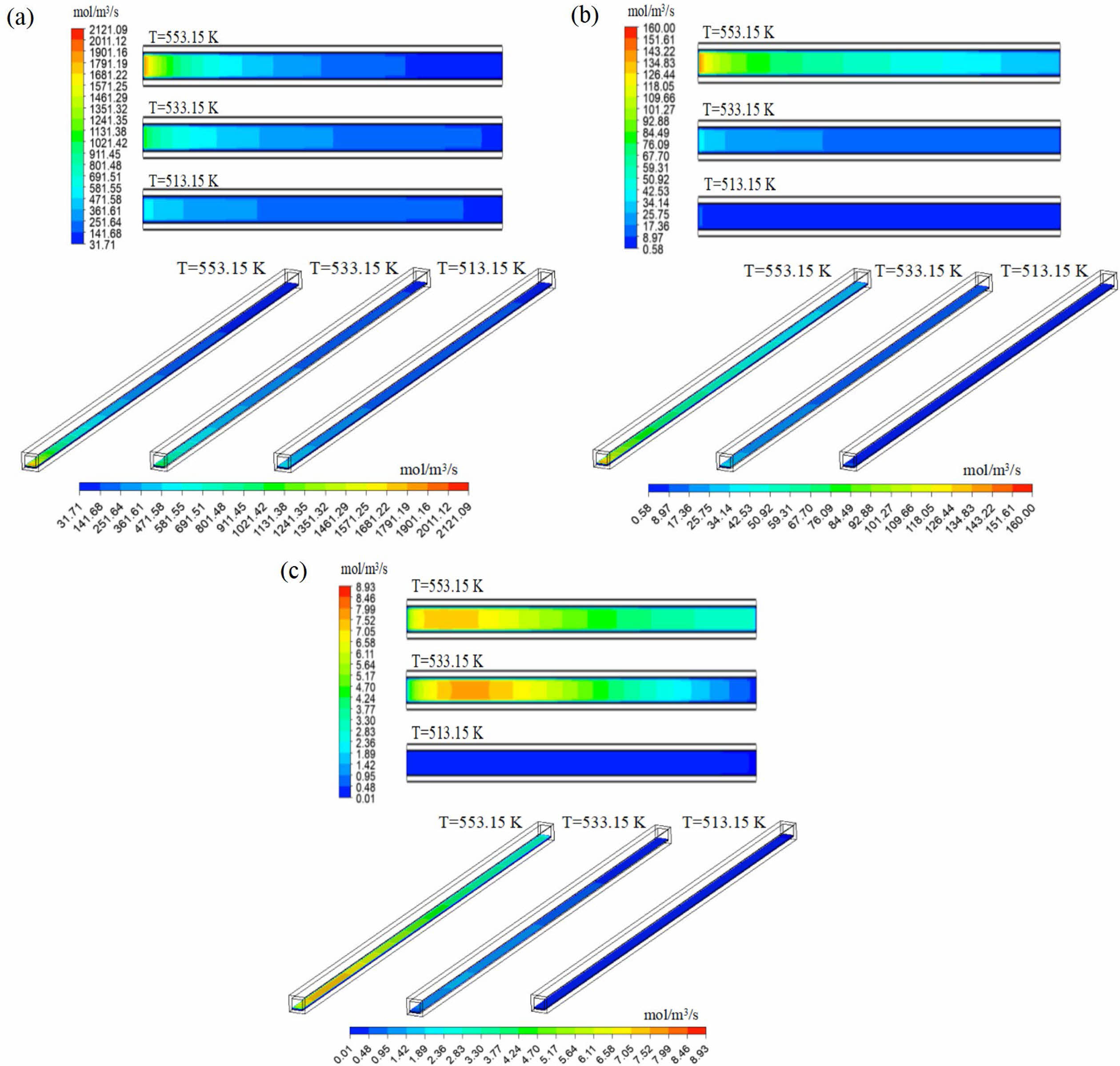
The reaction temperature directly affects the methanol steam reforming reaction rate. Fig. 9 is the distribution nephogram of methanol steam reforming reaction (MSR), methanol decomposition reaction (MD) and water-gas shift reaction (WGS) in the reforming catalytic layer at different reaction temperatures, in which the two-dimensional plane nephogram is the 1/2 cross-section position of the height of the reforming catalytic layer. It can be seen from the Fig. 9 that the highest points of the three reaction rates are located near the inlet of the reformer, and the lowest points of the reaction rates are located at the outlet of the reformer. MSR reaction is similar to MD reaction, and the highest reaction rate is located at the inlet of reformer. With the progress of the reaction, the reaction rate gradually decreases and reaches the minimum at the outlet of the reformer. In contrast to WGS, the reaction rate increases first and then decreases along the flow channel in the reformer as the reaction progresses. With the decrease of reaction temperature, the reaction rates of the three groups also decreased, and the maximum reaction rates all decreased to varying degrees. It can be seen that the reaction temperature has a great influence on the chemical reaction rate. Higher temperature leads to higher reaction rate, so the more intense the reaction between CH3OH and H2O, the more reactants are consumed, which promotes the formation of products.
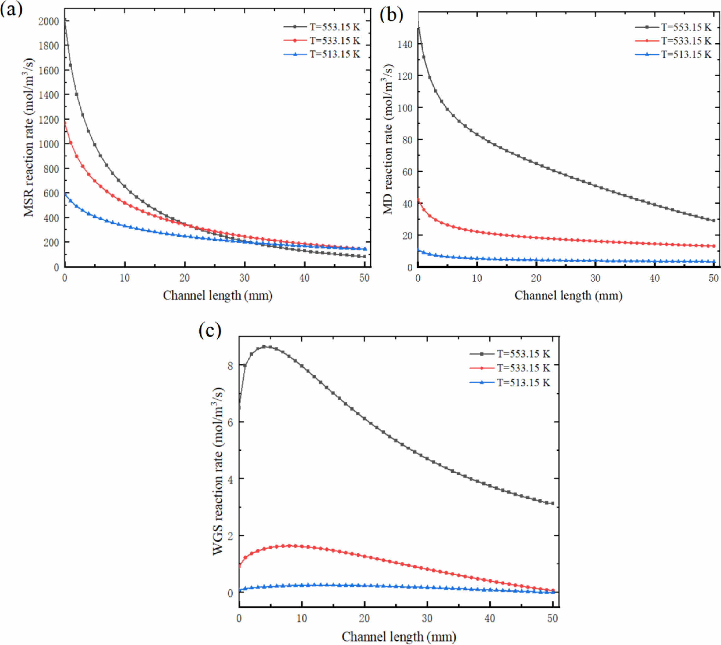
Fig. 10 shows the variation curves of MSR, MD and WGS at the center of reforming catalytic layer at different reaction temperatures. It can be seen that the reaction rate of MSR decreased from 2121.09 mol/m3/s to 82.96 mol/m3/s at 553.15 K; Under these conditions, the reaction rate of MD decreased from 160 mol/m3/s to 29.04 mol/m3/s, and that of WGS increased from 6.5 mol/m3/s to 8.65 mol/m3/s, and then decreased to 3.13 mol/m3/s. Under the same conditions of 533.15 K, the highest reaction rates of MSR, MD and WGS are 1176.95 mol/m3/s, 42.33 mol/m3/s and 1.64 mol/m3/s respectively; Under the same condition of 513.15 K, the highest reaction rate of MSR is only 589.12 mol/m3/s, and that of MD is only 10.69 mol/m3/s. It can also be seen in the Fig. 10 that in MSR, the reaction rate at the front end of the reactor drops rapidly, and the change range is large; With the progress of the reaction, the change of reaction rate in the middle and back end of the reactor is small. In MD, the reaction rate at the front end of the reactor still decreases to a large extent; However, at the middle and back end of the reactor, the reaction rate gradually decreases with a relatively constant change range. Similarly, with the decrease of reaction temperature, the change trend of the three reactions gradually decreased, and the change of reaction rate at the inlet and outlet of the reactor became more peaceful. The relationship among the three reactions in methanol steam reforming can also be obtained through the numerical values and changes in Fig. 10: MSR is the main reaction of methanol steam reforming reaction, which has the greatest influence on methanol reforming process and plays a leading role in determining the process of the reaction; MD is the side reaction and auxiliary reaction; The influence of WGS on methanol steam reforming process is minimal and almost negligible.
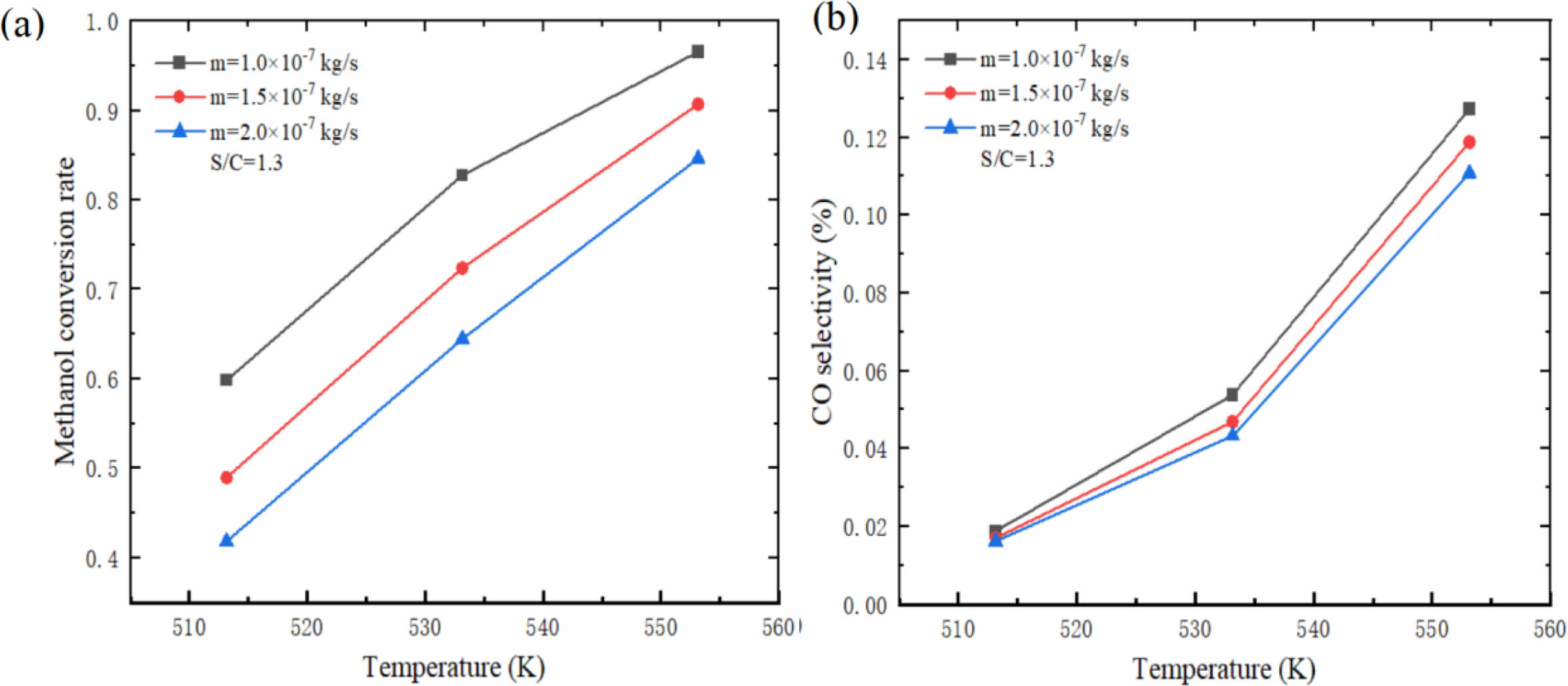
Fig. 11 shows the influence of different reaction temperatures on hydrogen production performance of micro-channel reformer. The results show that both methanol conversion rate and CO selectivity increase rapidly with the increase of reaction temperature, and the increase of CO selectivity increases with the increase of reaction temperature. This phenomenon occurs because the temperature has a great influence on the methanol steam reforming reaction rate. The higher the temperature, the more intense the methanol steam reforming reaction, the higher the reaction rate and the higher the methanol conversion rate. Similarly, with the increase of temperature, the more CH3OH is consumed, the more CO is produced and the CO selectivity increases. It is particularly noted that although higher temperature can improve the methanol conversion rate, CO will also increase sharply, which is very unfavorable to the outlet gas components. Therefore, the methanol conversion rate should be guaranteed and the reaction temperature should be controlled in a suitable range to avoid a large amount of CO gas.
Effect of S/C
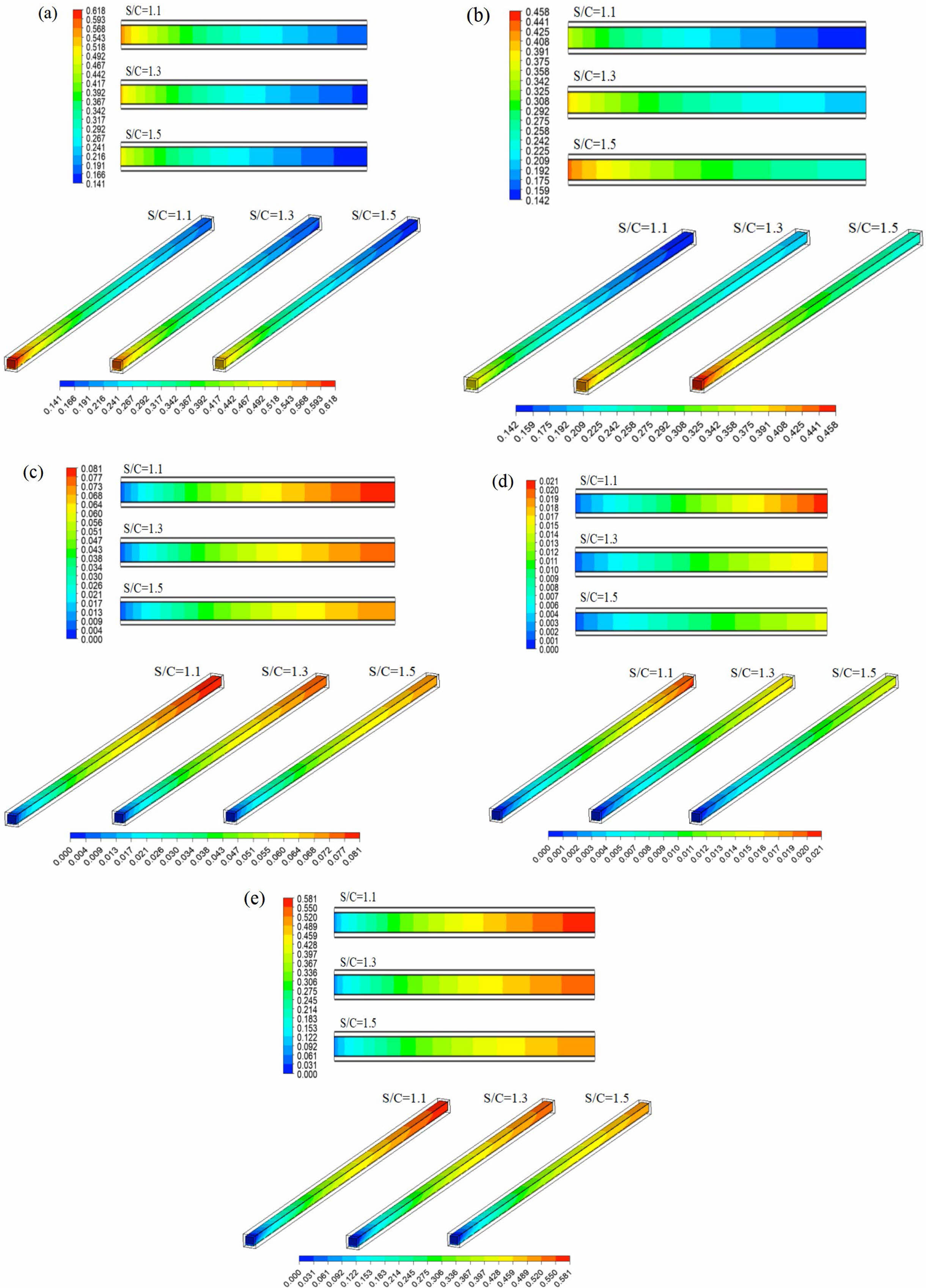
The effects of different S/C on the components of the reformer gas were investigated at the inlet mass flow rate of 1.5×10⁻⁷ kg/s and reaction temperature of 533.15 K. Fig. 12 shows the mass fraction distribution nephogram of each component in the reforming channel under different S/C, in which the two-dimensional plane nephogram is the 1/2 cross-sectional position of the reforming channel height. The results show that with the increase of S/C, the mass fraction of CH3OH at the inlet of the reforming channel decreases gradually, and at the outlet of the reforming channel, its mass fraction also gradually decreases. On the contrary, with the increase of S/C, the mass fraction of H2O at the inlet of the reforming channel increases gradually, and its mass fraction at the outlet of the reforming channel also increases gradually. The mass fractions of H2, CO and CO2 have the same trend, and their mass fractions gradually decrease with the increase of S/C at the outlet of the reforming channel. The reason for this is that the increase of S/C reduces the proportion of CH3OH in reactants and increases the content of H2O, which leads to the gradual decrease in the mass fraction of CH3OH and the gradual increase in the mass fraction of H2O at the inlet of reforming channel. CH3OH is the main reactant in the whole methanol steam reforming reaction. However, with the increase of S/C, the content of CH3OH at the inlet of reforming channel decreases, which leads to the decrease of H2, CO and CO2 components in the whole methanol steam reforming reaction, and the mass fraction at the outlet of reforming channel also decreases one after another.
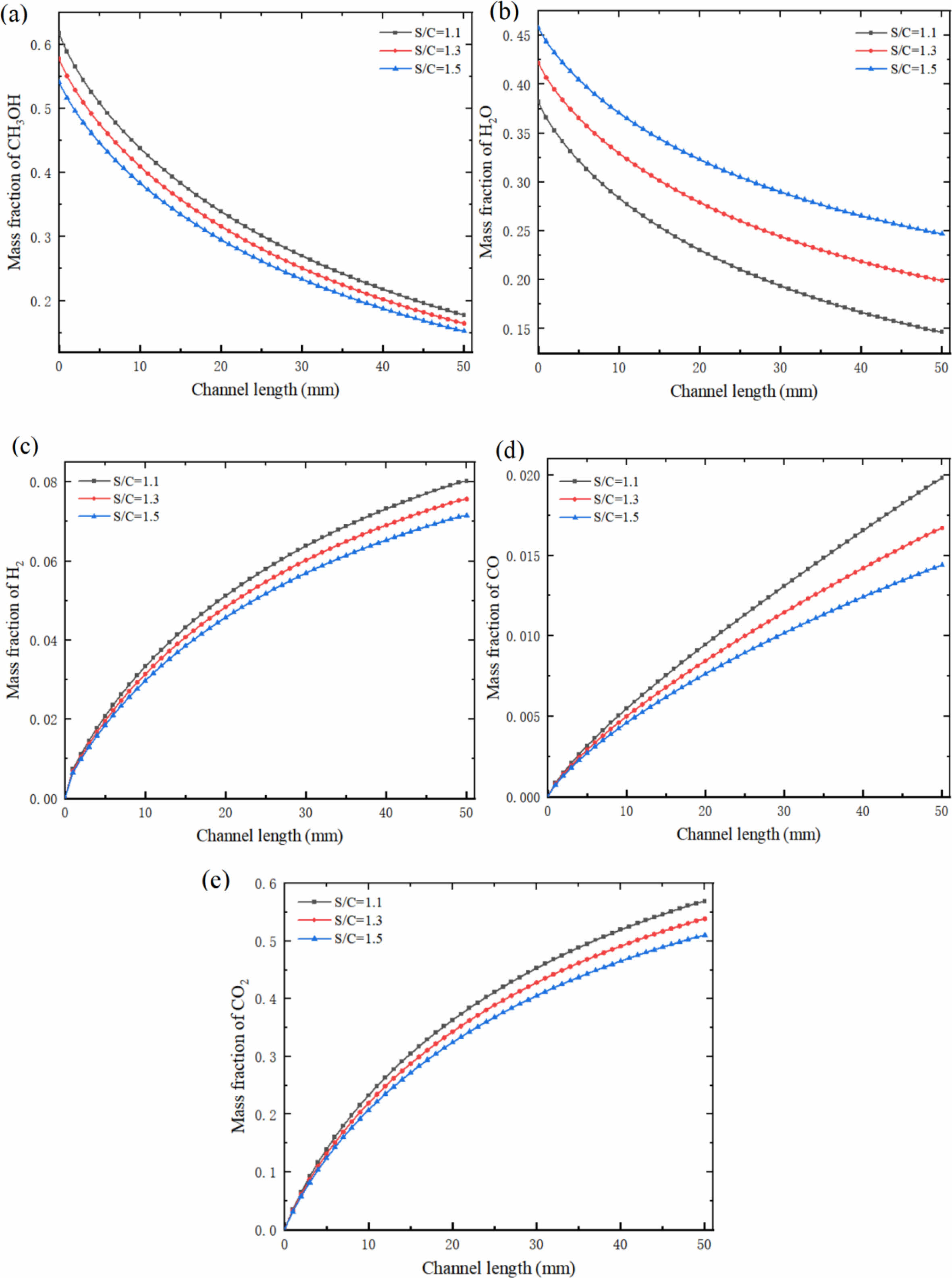
Fig. 13 shows the mass fraction variation curves of each component at the center of the reforming channel under different S/C. When the S/C was 1.1, the mass fraction of CH3OH decreased from 0.618 to 0.178. Under this condition, the mass fraction of H2 was 0.08, and the mass fraction of CO was 0.02. When the S/C was 1.3 and 1.5, the mass fraction of CH3OH decreased from 0.578 to 0.165, 0.542 to 0.152, H2 to 0.076 and 0.072, CO to 0.017 and 0.014, respectively. It can also be seen from the Fig. 13 that the consumption rate of reactants and the formation rate of products have the same rules as those in Chapters 3.1 and 3.2. With the increase of S/C, this trend gradually decreases. The formation rate of CO in the whole methanol steam reforming reaction is still high, and the formation rate of CO decreases with the increase of the S/C.
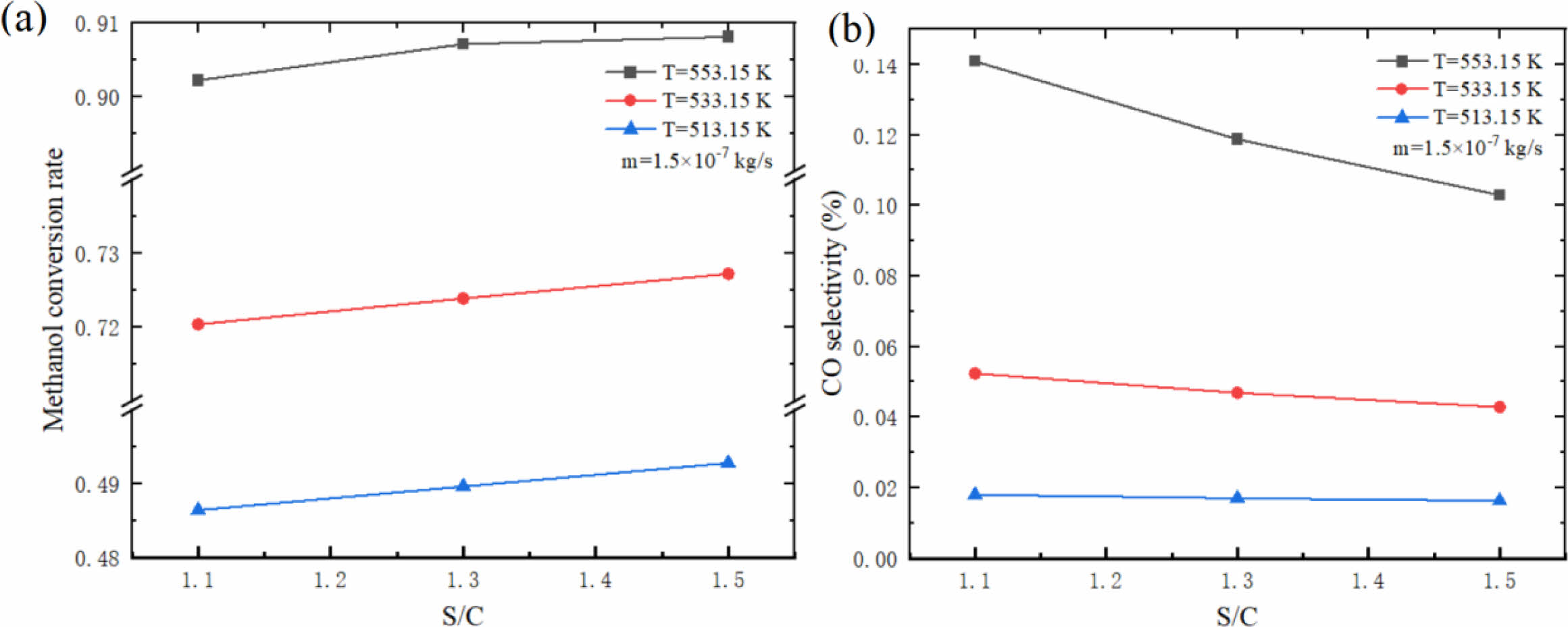
Fig. 14 shows the influence of different S/C on hydrogen production performance of micro-channel reformer. The results show that the methanol conversion rate increases with the increase of S/C, while the CO selectivity decreases. This phenomenon is mainly influenced by the characteristics of the main reaction. For the MSR which affects the methanol conversion rate, the larger S/C is beneficial to promote the forward reaction, and promote more CH3OH and H2O to react to produce H2 and CO2, thus reducing the CO selectivity. Although a larger S/C can improve the methanol conversion rate and reduce the CO selectivity, it is worth considering that due to the relatively large specific heat of H2O, the larger S/C will make it more difficult to evaporate and heat the mixed solution. Therefore, it is particularly important to choose the appropriate S/C.
|
Fig. 4 Mass fraction of (a) CH3OH, (b) H2O, (c) H2, (d) CO and (e) CO2 in reforming channel under different inlet mass flow rates. |
|
Fig. 5 Mass fraction of (a) CH3OH, (b) H2O, (c) H2, (d) CO and (e) CO2 at the center of reforming channel under different inlet mass flow rates. |
|
Fig. 6 Effect of different inlet mass flow rates on (a) methanol conversion rate and (b) CO selectivity of micro-channel reformer. |
|
Fig. 7 Mass fraction of (a) CH3OH, (b) H2O, (c) H2, (d) CO and (e) CO2 in reforming channel at different reaction temperatures. |
|
Fig. 8 Mass fraction of (a) CH3OH, (b) H2O, (c) H2, (d) CO and (e) CO2 at the center of reforming channel at different reaction temperatures. |
|
Fig. 9 Reaction rate in reforming catalytic layer at (a) MSR, (b) MD and (c) WGS reaction temperatures. |
|
Fig. 10 Reaction rate at the center of reforming catalytic layer at (a) MSR, (b) MD and (c) WGS reaction temperatures. |
|
Fig. 11 Effect of different reaction temperatures on (a) methanol conversion rate and (b) CO selectivity of micro-channel reformer. |
|
Fig. 12 Mass fraction of (a) CH3OH, (b) H2O, (c) H2, (d) CO and (e) CO2 in reforming channel under different S/C. |
|
Fig. 13 Mass fraction of (a) CH3OH, (b) H2O, (c) H2, (d) CO and (e) CO2 at the center of reforming channel under different S/C. |
|
Fig. 14 Effect of different S/C on (a) methanol conversion rate and (b) CO selectivity of micro-channel reformer. |
In this study, a three-dimensional numerical model of methanol steam reforming micro-channel reactor was established, and the mass transport process during hydrogen production was studied. The effects of different inlet mass flow rate, reaction temperature and S/C on the mass change of each component, chemical reaction rate and hydrogen production performance of micro-channel reformer were studied by numerical model. The conclusions are as follows:
1. When the reaction temperature and S/C are constant, with the increase of the inlet mass flow rate, the mass fraction of CH3OH at the outlet of the reforming channel gradually increases and the methanol conversion rate gradually decreases; The mass fraction of CO at the outlet of reforming channel decreases, and the CO selectivity decreases gradually. Therefore, the selection of inlet mass flow should be based on the requirement of methanol conversion rate, and the larger inlet mass flow should be preferred.
2. When the inlet mass flow rate and S/C are constant, with the increase of reaction temperature, the mass fraction of CH3OH at the outlet of reforming channel decreases gradually and the methanol conversion rate increases; The mass fraction of CO at the outlet of reforming channel increases, and the CO selectivity increases rapidly. Therefore, the methanol conversion rate should be guaranteed and the reaction temperature should be controlled in a suitable range to avoid a large amount of CO gas.
3. When the inlet mass flow rate and reaction temperature are constant, with the increase of S/C, the methanol conversion rate increases and the CO selectivity decreases, so increasing the S/C can improve the reforming hydrogen production performance of micro-channel reformer. However, in practical application, a higher S/C means an increase in H2O content, which makes it more difficult to evaporate and heat the mixed solution, so it is necessary to increase the S/C appropriately.
- 1. M. Marappan, M.K. Vijayakrishnanb, K. Palaniswamy, K. Manoharan, T. Kumaresan, and J. Arumughan, J. Ceram. Process. Res. 22[2] (2021) 131-142.
-

- 2. B.-S. Koh and S.-C. Yi, J. Ceram. Process. Res. 18[11] (2017) 810-814.
-
- 3. S.A. Li, R.Q. Wei, X.R. Lv, W.Q. Ye, Q.W. Shen, and G.G. Yang, Int. J. Electrochem. Sci. 15 (2020) 7407-7416.
-
- 4. S.A. Li, R.Q. Wei, Q.W. Shen, and G.G. Yang, Int. J. Electrochem. Sci. 15 (2020) 7152-7162.
-
- 5. H.-C. Lee, J. Lee, J.-A. Lee, Y.-W. Heo, J.-H. Lee, and J.-J. Kim, J. Ceram. Process. Res. 21[2] (2020) 208-212.
-
- 6. S.W. Perng and R.F. Horng, Int. J. Hydrog. Energy. 42[38] (2017) 24372-24392.
-
- 7. F. Yao, Y.P. Chen, and G.P. Peterson, Int. J. Heat Mass Transf. 64 (2013) 418-425.
-
- 8. J.D. Holladay, Y. Wang, and E. Jones, Chem. Rev. 104[10] (2004) 4767-4790.
-
- 9. Z. Li, G.G. Yang, S.A. Li, Q.W. Shen, F.C. Yang, H. Wang, and X.X. Pan, Int. J. Hydrog. Energy. 46[38] (2021) 19822-19834.
-
- 10. D.R. Palo, R.A. Dagle, and J.D. Holladay, Chem. Rev. 107[10] (2007) 3992-4021.
-
- 11. J.B. Xu, T.S. Zhao, W.W. Yang, and S.Y. Shen, Int. J. Hydrog. Energy. 35[16] (2010) 8699-8706.
-
- 12. H.C. Yang, L.S. Roselin, and F.W. Chang, Sci. Adv. Mater. 3[6] (2011) 1038-1045.
-
- 13. Y.C. Wang, Q. Wu, D.Q. Mei, and Y.D. Wang, Int. J. Energy Res. 45[4] (2021) 6163-6173.
-
- 14. S. Gumber and A.V.P. Gurumoorthy, Methanol. (2018) 661-674.
-
- 15. P. Ribeirinha, M. Boaventura, J.C.B. Lopes, J.M. Sousa, and A. Mendes, Int. J. Hydrog. Energy. 39[35] (2014) 19970-19981.
-
- 16. A. Chougule and R.R. Sonde, Int. J. Hydrog. Energy. 44[57] (2019) 29937-29945.
-
- 17. M. Satheeshkumar, M.R. Thansekhar, and R. Pandiyarajan, J. Ceram. Process. Res. 22[6] (2021) 679-691.
-
- 18. B.A. Peppley, J.C. Amphlett, L.M. Kearns, and R.F. Mann, Appl. Catal. A-Gen. 179[1-2] (1999) 31-49.
-
- 19. S.P. Asprey, B.W. Wojciechowski, and B.A. Peppley, Appl. Catal. A-Gen. 179 [1-2] (1999) 51-70.
-
- 20. K. Ghasemzadeh, P. Morrone, A.A. Babalou, and A. Basile, Int. J. Hydrog. Energy. 40[10] (2015) 3909-3918.
-
- 21. C.J. Jiang, D.L. Trimm, M.S. Wainwright, and N.W. Cant, Appl. Catal. A-Gen. 93[2] (1993) 245-255.
-
- 22. D.Q. Mei, M. Qian, Z.H. Yao, B.H. Liu, X.Y. Lou, and Z.C. Chen, Int. J. Hydrog. Energy. 37[23] (2012) 17817-17827.
-
- 23. D.Q. Mei, L.W. Liang, M. Qian, and Y.B. Feng, Int. J. Hydrog. Energy. 39[31] (2014) 17690-17701.
-
- 24. X.R. Zhuang, X. Xia, X.H. Xu, and L. Li, Int. J. Hydrog. Energy. 45[19] (2020) 11024-11034.
-
- 25. A. Mastalir, B. Frank, A. Szizybalski, H. Soerijanto, A. Deshpande, M. Niederberger, R. Schomäcker, R. Schlögl, and T. Ressler, J. Catal 230[2] (2005) 464-475.
-
- 26. A. Karim, J. Bravo, D. Gorm, T. Conant, and A. Datye, Catal. Today. 110[1-2] (2005) 86-91.
-
- 27. Y.Z. Hao, X.Z. Du, L.J. Yang, Y.Q. Shen, and Y.P. Yang, Int. J. Hydrog. Energy. 36[24] (2011) 15611-15621.
-
- 28. J.S. Suh, M.T. Lee, R. Greif, and C.P. Grigoropoulos, J. Power Sources. 173[1] (2007) 458-466.
-
- 29. Y.Y. Tang, Y. Wang, W.Q. Long, G. Xiao, Y.Q. Wang, and W.X. Li, Energy. 283 (2023) 129098.
-
- 30. S.W. Perng and H.W. Wu, Appl. Energy. 323 (2022) 119510.
-
- 31. J.J. Chen, T.F. Li, F.M. Meng, and P.M. Ming, Int. J. Hydrog. Energy. 45[35] (2020) 17088-17103.
-
- 32. T. Zhang, X.Y. Tang, W.W. Yang, and X. Ma, Int. J. Hydrog. Energy. 48[3] (2023) 879-893.
-
- 33. X.R. Zhuang, X.H. Xu, L. Li, and D.X. Deng, Int. J. Hydrog. Energy. 45[29] (2020) 14790-14805.
-
 This Article
-
2024; 25(2): 285-299
Published on Apr 30, 2024
- 10.36410/jcpr.2024.25.2.285
- Received on Feb 13, 2024
- Revised on Mar 4, 2024
- Accepted on Mar 19, 2024
Services
Shared
Correspondence to
- Qiuwan Shen
-
Marine Engineering College, Dalian Maritime University, Dalian, China
Tel : +86-18624118015 Fax: +0411-84728659 - E-mail: Shenqiuwan@dlmu.edu.cn
Clean-Energy Research Institute(CRI), Hanyang University, 222, Wangsimni-ro, Seongdong-gu, Seoul, 04763, Korea
E-mail: jcpr@hanyang.ac.kr