


- Preparation and sinterability of submicron titanium carbide powders synthesized with phenolic resin as carbon source by carbothermal reduction
Huijuan Qiua, Hongkang Weia,*, Shifeng Renb, Lingjun Sunb, Jia Lia, Zihan Wangb, Lin Zhaoa, Chang-an Wangc and Zhipeng Xiec
aAdvanced Ceramic Materials Research Institute, School of Materials Science and Engineering, Jingdezhen Ceramic University, Jingdezhen, Jiangxi 333403, People’s Republic of China
bJingdezhen Huaxun Special Ceramics Company Limited, Jingdezhen, Jiangxi 333426, People’s Republic of China
cState Key Laboratory of New Ceramics and Fine Processing, School of Materials Science and Engineering, Tsinghua University, Beijing, 100084, People’s Republic of ChinaThis article is an open access article distributed under the terms of the Creative Commons Attribution Non-Commercial License (http://creativecommons.org/licenses/by-nc/4.0) which permits unrestricted non-commercial use, distribution, and reproduction in any medium, provided the original work is properly cited.
Titanium carbide powders were synthesized under an argon atmosphere using titanium dioxide and pyrolysis carbon derived from pyrolyzed phenolic resin as raw materials. The effects of synthesis temperature, holding time, and C/Ti molar ratio on the phase composition and morphology of the synthesized powders were investigated. The results show that the pyrolyzed phenolic resin at 1000 ℃ is a carbon source composed of amorphous and crystalline carbon. Increasing the C/Ti molar ratio of the mixed powder can reduce the content of titanium oxide impurity, indicating the improvement in the purity of TiC powder. In addition, the C/Ti molar ratio can also significantly affect the morphology of the synthesized TiC powders. SEM and EDS results exhibit that the atomic content on the surface of TiC particles is closely correlated with the atomic distribution on the surface of the particles. TiC powder with a median particle size of 384 nm could be synthesized at 1500 ℃ for 30 min at the C/Ti molar ratio of 2.3:1. In addition, the sinterability of the synthesized TiC powder was preliminarily discussed. The hardness and fracture toughness of the TiC ceramic sintered at 2000 ℃ under 40 MPa with a dwell time of 2 h are 15.92 GPa and 3.22 MPa·m1/2, respectively.
Keywords: Titanium carbide powder, Phenolic resin, Pyrolysis carbon.
Titanium carbide (TiC) is a transition metal carbide with a NaCl-type face-centered cubic structure. Its chemical bond is a mixed bond type composed of ionic, metal, and covalent bonds. Titanium carbide has excellent properties embracing high hardness, superior wear resistance, outstanding elastic modulus, low thermal conductivity as well as excellent electrical conductivity, making it suitable for hard alloy, coating material, cutting tool material, optical material, and metal crucible [1-4].
Hitherto, various methods, including carbothermal reduction method [5-7], self-propagation high-temperature synthesis (SHS) [8], sol-gel [9], and chemical vapor deposition (CVD), have been employed to synthesize TiC powder. Although, compared with other methods, self-propagation high-temperature synthesis has advantages in time and energy consumption, its application in synthesizing TiC is still restricted, since the morphology and purity of the synthesized TiC powder by this method are sensitive to process parameters. Song et al. [10] successfully fabricated nano-sized TiC powder (about 80 nm) by a chemical vapor deposition method. Due to its advantage in purity and disadvantage in yield, the CVD method tends to be applied to prepare TiC films and coatings. It was reported that TiC powder synthesized by the sol-gel process is generally of high purity with tunable morphology. However, it is not a feasible method for the industrial production of TiC because of its complex process and low yield. In contrast to the above-mentioned synthesis methods, the carbothermal reduction method embodies the characteristics of straightforward procedures, low cost, and superiority in mass production, which is currently the mainstream process for the industrial production of TiC powder. In the present carbothermal reduction production process, TiC powder was usually fabricated at 1700-2100 ℃ for 10-24 h with titanium dioxide and carbon black as raw materials [11, 12]. Nevertheless, the current carbothermal reduction process possesses high energy consumption and the morphology of the synthesized powder is inhomogeneous. Hence, it is significant to obtain ultra-fine powder with homogeneous morphology and reduce the energy consumption during the carbothermal reduction process.
Phenolic resin, one of the earliest synthesized artificial resins, has been utilized widely in coatings, plastics, and adhesives owing to its low cost and facile synthesis process [13]. Thermosetting phenolic resin is an attractive carbon source with a high carbon yield and high chemical activity after high-temperature pyrolysis. However, if introduced directly into raw materials, phenolic resin will trigger large-volume expansion and severe agglomeration during the synthesis process of TiC powder, which is detrimental to the precise control of synthesis conditions. Herein, TiC powder was obtained by carbothermal reduction using pyrolyzed phenolic resin as the carbon source The effects of synthesis temperature, holding time, and C/Ti molar ratio on the phase composition and morphology of the synthesized powders was systematically investigated. In addition, the sinterability of the obtained TiC powders was preliminarily discussed.
Characterization of starting material
Phenolic resin (BR, Shanghai Aladdin Biochemical Technology Co., LTD, China) and TiO2 (AR, Nanjing Shenghe Chemical Reagent Factory, China) were used to synthesize TiC powder. To characterize the sinterability of the synthesized TiC powders, phenolic resin was introduced into the TiC matrix as a binder and sintering additive.
Synthesis and sintering of TiC powders
Phenolic resin was calcinated under an argon atmosphere at 1000 ℃ for 3 h and then, cooled to room temperature. The as-pyrolyzed carbon powder was ground through a 100-mesh sieve before being used. The pyrolysis carbon and TiO2 were sufficiently stirred in absolute ethyl alcohol at designated ratios, followed by ultrasonic dispersion for 1 h. At last, the obtained slurry was dried using rotary evaporation and ground to pass a 100-mesh screen. The mixed powders were uniaxially dry pressed under 8 MPa with a steel die and then calcined in an argon atmosphere under the calcination conditions listed in Table 1. In addition, in order to characterize the sinterability of the obtained TiC powders, the titano-oxide-free TiC-3.3 powder prepared at 1500 ℃ for 1 h was mixed with 2 wt% phenolic resin by wet ball milling with absolute ethyl alcohol for 5 h, and subsequently dried and sieved. The obtained powder mixtures were hot pressed at 2000 ℃ under 40 MPa in a vacuum for 1 h and 2 h, and the prepared ceramic samples were marked as TiC-2PR-1 and TiC-2PR-2, respectively.
Characterization
The phase compositions of the obtained TiC powders were determined by X-ray diffraction analysis (XRD, Cu Kα, UItima IV, Nippon Science Corporation) with a step width of 0.02° in the 2θ range of 10°~80° at a scanning speed of 6°/min. The structure of the selected sample was refined by the Rietveld method using FullProf software, for which the data were collected in the 2θ range of 5°~140° at a scanning speed of 1.2°/min. The total carbon and oxygen content in the synthesized powders were examined by a Carbon-sulfur analyzer (LECO CS844) and Oxygen-nitrogen-hydrogen Determinator (LECO ONH836), respectively. The particle size distribution of the obtained powders was measured by nano size and zeta potential analyzer (DLS, Zetasizer Nano ZS90). The grain size analysis of the sintered ceramic was performed using the ImageJ software according to a minimum of 250 measurements. The chemical state of the synthesized powder was characterized by X-ray photoelectron spectroscopy (XPS). The morphology and chemical composition of the synthesized powders and the densified ceramic were observed by field emission scanning electron microscope (SEM, ZEISS Gemini 300) equipped with an energy dispersive spectrometer (EDS). High resolution transmission electron microscopy (HR-TEM) and selected area electron diffraction (SAED) measurements were implemented on a JEOL F200 TEM.
After grinding and polishing the sintered ceramic, the bulk density, apparent porosity, and water absorption were determined using Archimedes’ method. The Vickers hardness of the ceramic specimens was measured by a Micro Vickers hardness tester (2500B, Instron, USA) using a 2-kg load and a 15-s loading time. According to the indentation method, the fracture toughness of the ceramic sample was calculated based on the formula provided by Gu et al. [14].
|
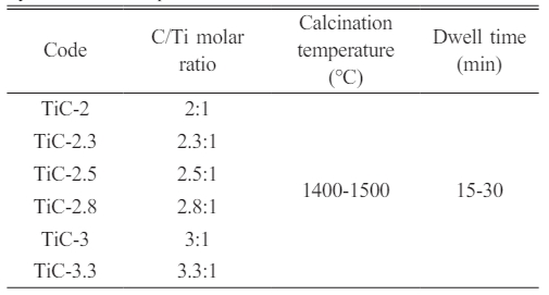
Table 1 Reactant ratios and calcination conditions in the synthesis of TiC powder. |
Phase composition and morphology of the pyrolyzed phenolic resin
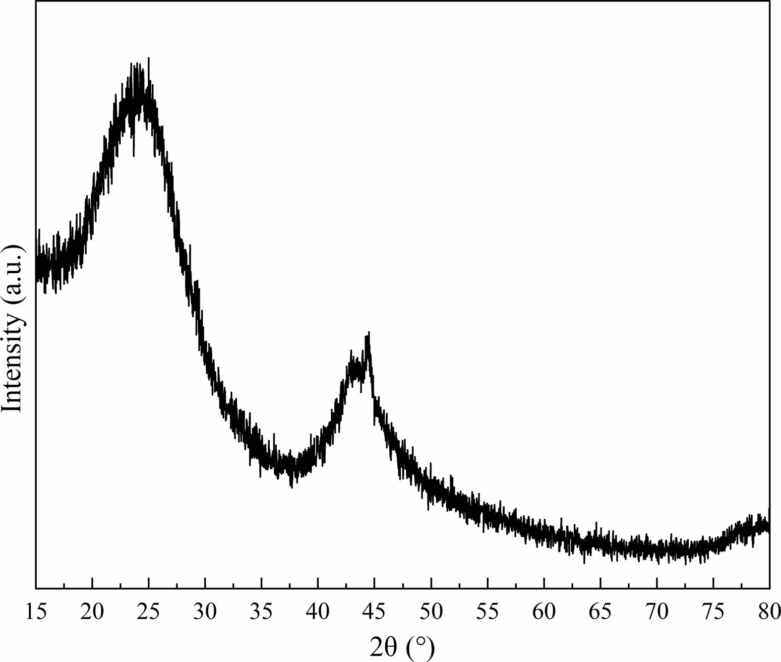
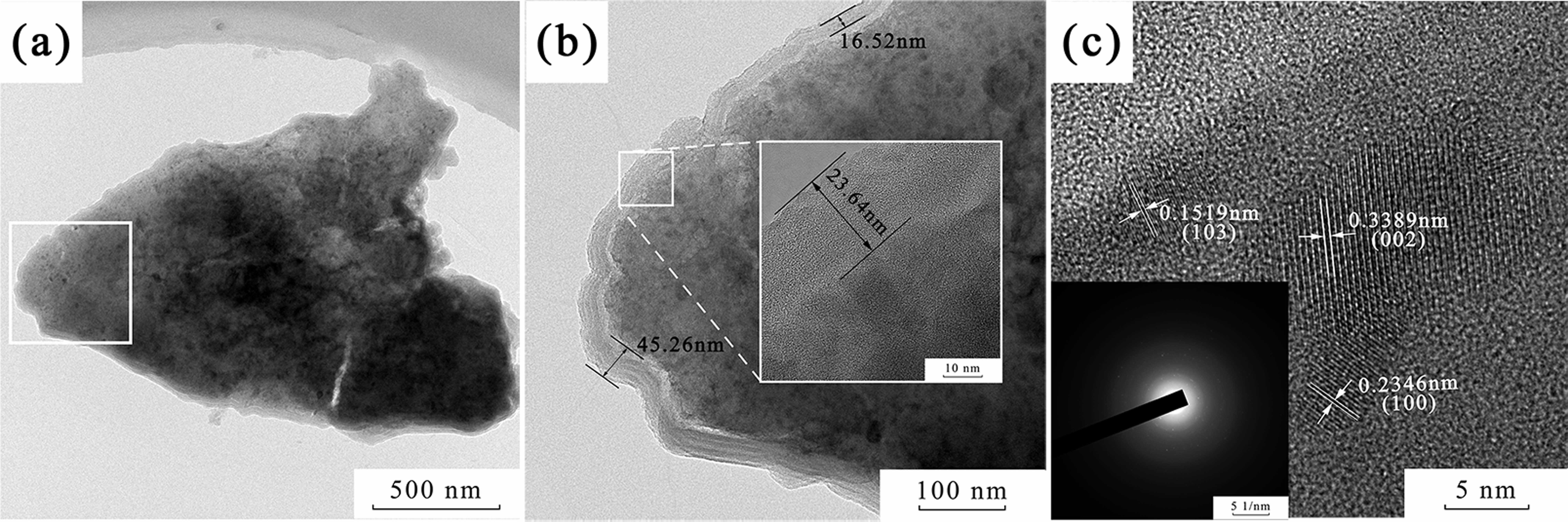
The XRD pattern of the carbonized phenolic resin is shown in Fig 1. The broad diffraction peaks, located at around 23° and 43°, were correlated to the (002) and (10l ) crystal planes of the graphite phase, respectively. In particular, the diffraction peak of the (10l ) crystal plane was split into two peaks, corresponding to the (100) and (101) planes, illustrating that a three-dimensional interplanar correlation existed in the carbonized phenolic resin [15, 16]. The morphology of the carbonized phenolic resin was observed by TEM and HRTEM, as demonstrated in Fig. 2. The carbonized phenolic resin appeared to be irregular morphology, assembled from amorphous particles and nanocrystals (Fig. 2a). Interestingly, the carbonized phenolic resin exhibited a kind of core-shell structure, in which the disordered lattice fringes of the shell were extremely similar to amorphous carbon [17, 18]. It could be speculated that the carbonized phenolic resin was wrapped by a layer of amorphous carbon with a thickness of 16.5~45.3 nm (Fig. 2b). Fig. 2c shows the ordered lattice fringes of the carbon nanocrystals, correlating to (002), (100), and (103) crystal planes of graphite structure, which confirmed the partial graphitization feature in the carbonized phenolic resin [19, 20]. Therefore, the carbonized phenolic resin is a kind of carbon source that contains a majority of amorphous carbon and a small amount of crystallized carbon [21].
Phase, chemical composition, and microstructure of the synthetic powders
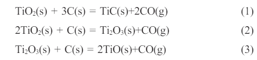
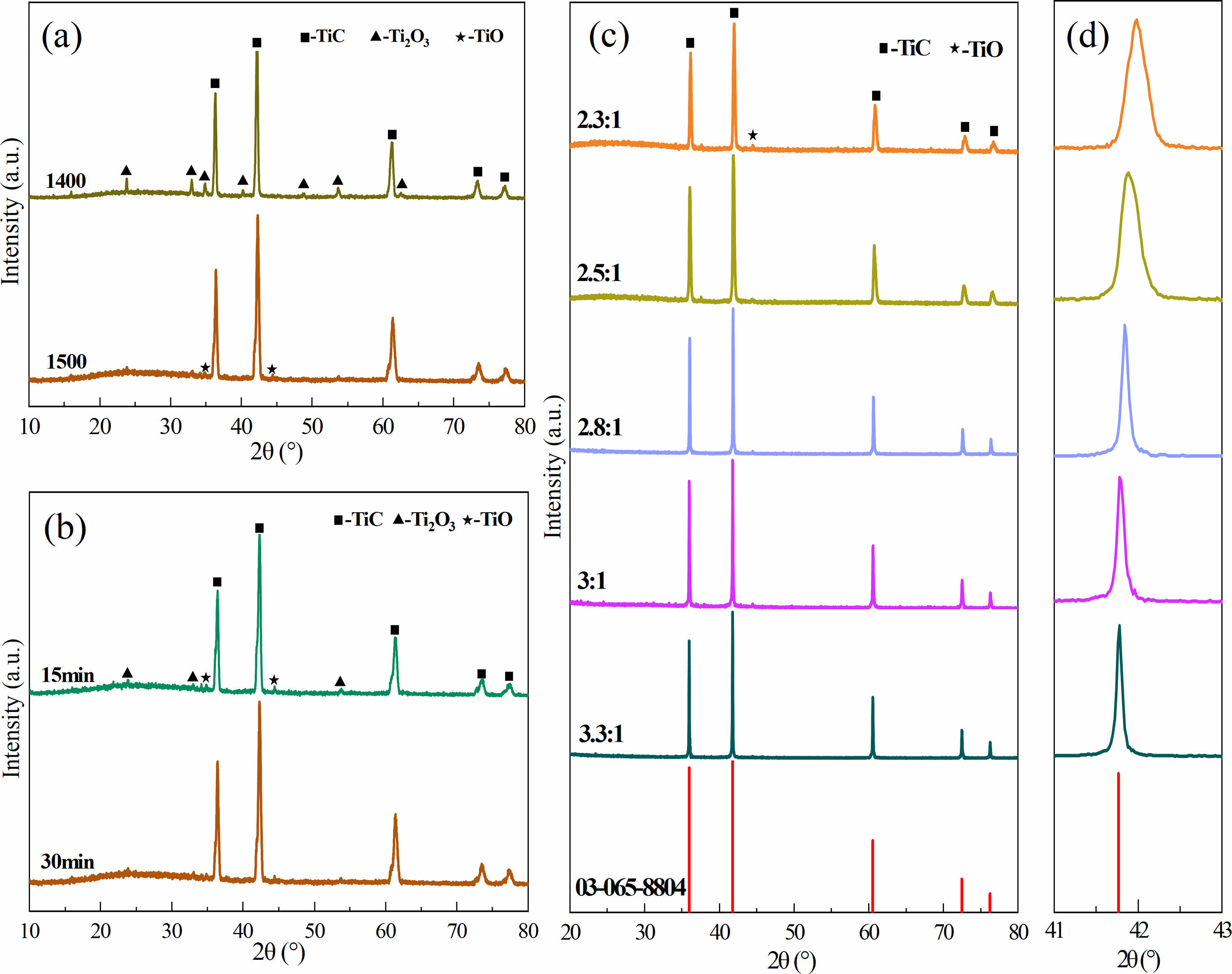
Fig. 3 shows the effects of synthesis temperature (Fig. 3a), holding time (Fig. 3b), and C/Ti molar ratios (Fig. 3c) on the phase composition and morphology of the obtained powders. As presented in Fig. 3a, TiC along with a small amount of Ti2O3 existed in the powder synthesized at 1400 ℃ with the C/Ti molar ratio of 2:1. When the synthesis temperature increased to 1500 ℃, the diffraction peak intensity of Ti2O3 decreased remarkably, while the diffraction peaks assigned to TiO appeared. It seems that the primary titano-oxide compound was Ti2O3 at the synthesis temperature of 1400 ℃. More oxygen atoms were replaced by carbon atoms as the synthesis temperature increased to 1500 ℃, resulting in the production of TiO, TiC, and CO. The formed CO gas was expelled from the furnace and the partial pressure of CO gas declined under vacuum, thus promoting the reaction toward the direction of TiC formation. The possible reactions are as follows:
The XRD patterns of the synthesized powders at different holding times at the synthesis temperature of 1500 ℃ and the C/Ti molar ratio of 2:1 are exhibited in Fig. 3b. The diffraction peaks of Ti2O3 and TiO existed in the synthesized powders with the holding time of both 15 min and 30 min. The phase compositions of the synthesized powders did not vary significantly as the holding time increased, indicating that the carbon content was insufficient to deplete oxygen atoms during the reactions when the C/Ti molar ratio was 2:1. Fig. 3c shows the XRD patterns of the synthesized powders at 1500 ℃ with holding time of 30 min at different C/Ti molar ratios. It can be seen that the diffraction peaks of Ti2O3 and TiO gradually weakened, while TiC peaks intensified progressively with the increase in the C/Ti molar ratio. Meanwhile, the full width at half maximum (FWHM) decreased steadily with the raised C/Ti molar ratio, revealing an increase in the TiC particle size. Fig. 3d depicts the magnified XRD diffraction patterns of the synthesized TiC powders with different C/Ti molar ratios in the 2 theta range of 41°~43°. It could be seen that an overall tendency to shift towards lower angles occurred as the carbon content increased. According to previous reports, TiO and TiC possess similar crystal structures, dictating that they were prone to form a solid solution (TiCxOy) [22, 9]. With increasing the carbon content, the number of oxygen atoms that were incorporated into the TiC lattice and substituted carbon atoms gradually decreased. The less content of oxygen atoms in the TiC lattice caused the larger crystal plane spacing and the shift of the TiC diffraction peaks since the radius of carbon atoms is larger than that of oxygen atoms.
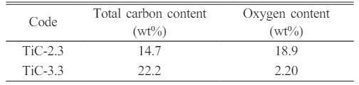
The total carbon and oxygen contents of TiC-2.3 and TiC-3.3 synthesized at 1500 ℃ for 30 min are displayed in Table 2. Although synthesized in the isothermal condition, the total carbon content (14.7 wt%) of TiC-2.3 was lower than that of TiC-3.3 (22.2 wt%), while its oxygen content (18.9 wt%) was remarkably higher than that of TiC-3.3 (2.20 wt%). Combined with the XRD data, it could be concluded that when the C/Ti molar ratio was 2.3:1, a small amount of titano-oxide compounds existed in the synthesized powder due to the insufficient carbon source, which caused a higher oxygen content in the synthesized powder. By increasing the carbon content of the initial powder, more oxygen atoms were substituted by carbon atoms as the C/Ti molar ratio increased to 3.3:1, resulting in dramatically lower oxygen and higher carbon contents, which is beneficial for TiC powder of high purity.
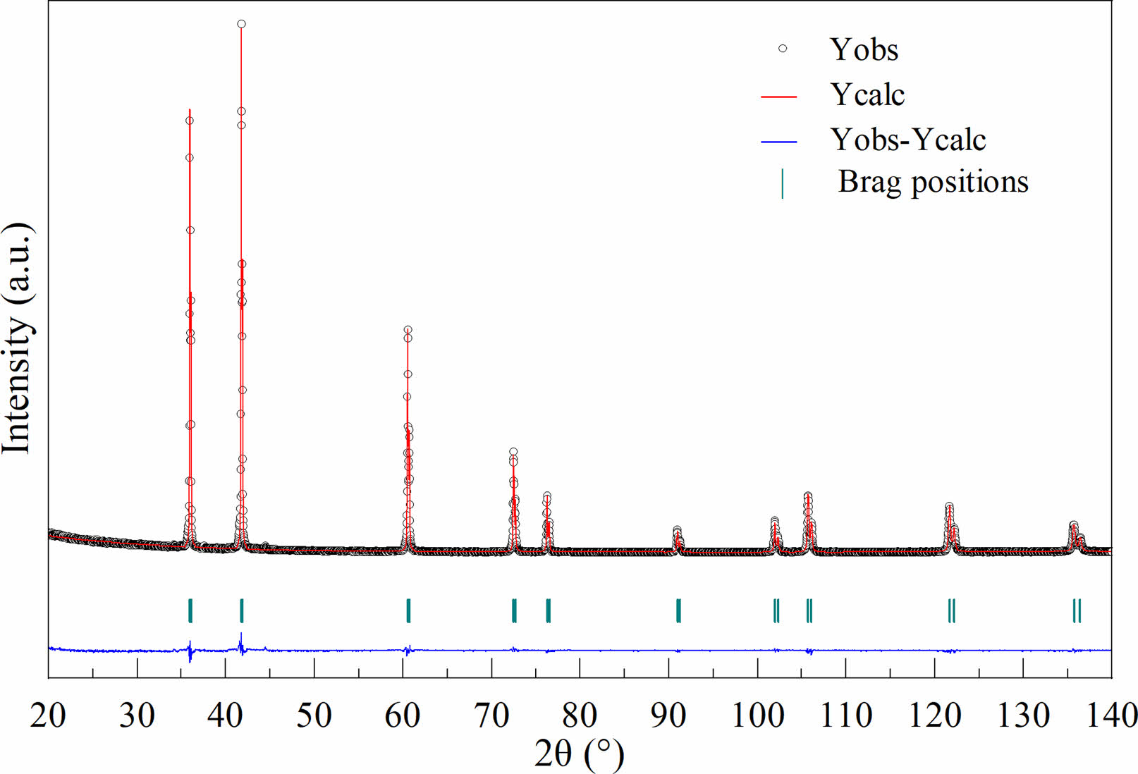
The Rietveld refinement of X-ray diffraction for TiC-3.3 at 1500 ℃ for 30 min is given in Fig. 4. It could be observed that the calculated data (Ycalc) was in good agreement with the experimental data (Yobs). Moreover, the reliability factors such as Rp, Rwp, Rexp, and χ2 were 6.61%, 9.62%, 6.90%, and 1.94 respectively. The lattice parameter (a=4.3211 Å) obtained through Rietveld refinement agreed well with that of TiC phase (4.322 Å, JCPDS No. 03-065-8804).
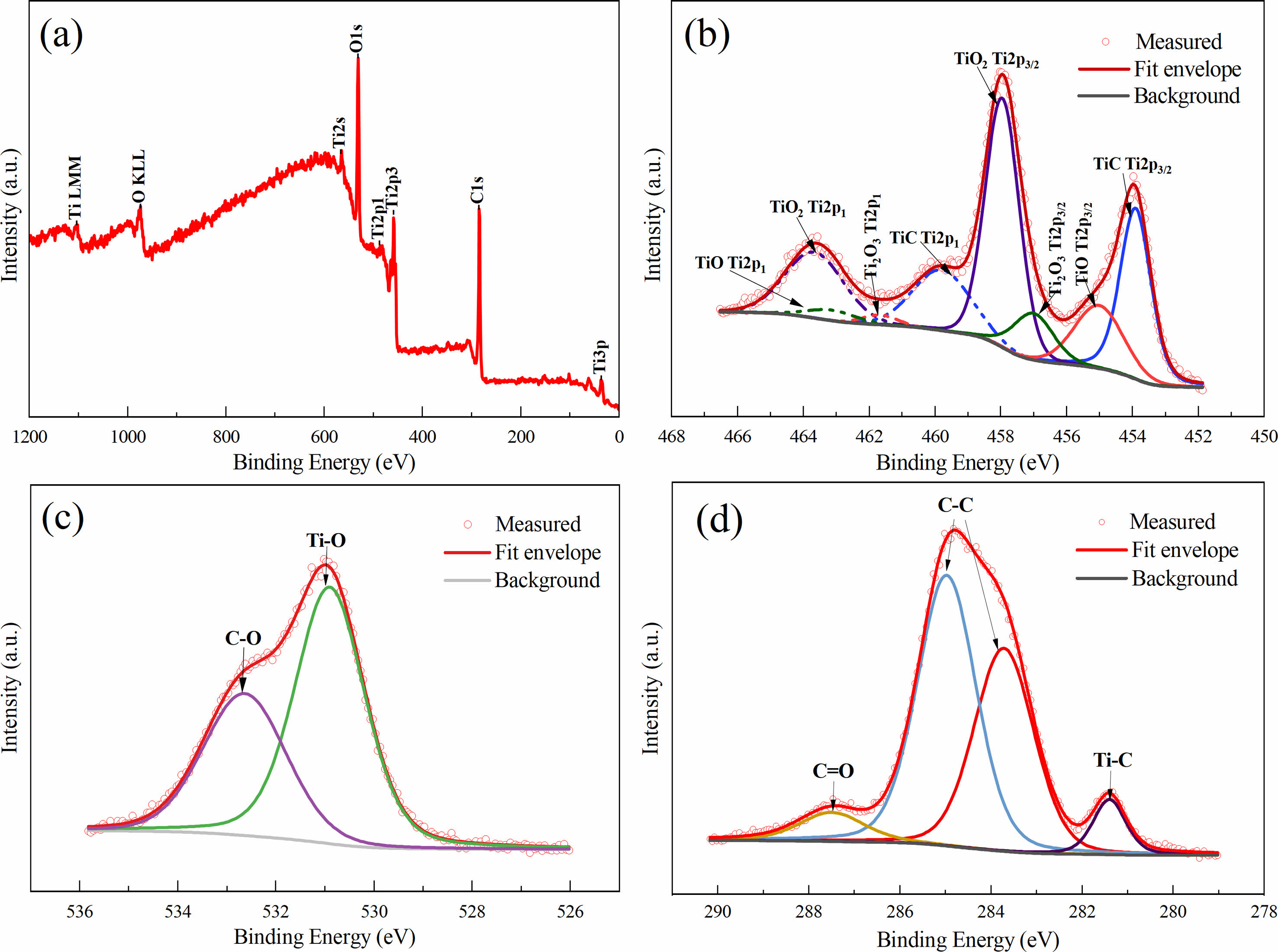
Fig. 5 depicts the XPS spectra of TiC-3.3 calcined at 1500 ℃ for 30 min. The XPS spectra showed that Ti, O, and C elements existed on the surface of TiC powder (Fig. 5a). As displayed in Fig. 5b, there were four groups of orbital spin-splitting peaks in the XPS spectrum of Ti 2p. Among these peaks, Ti (2p3/2) 453.9 eV and Ti (2p1) 459.79 eV may correspond to the Ti-C bond from TiC. The peaks at 457.96 eV and 463.67 eV were close to Ti (2p3/2) and Ti (2p1) from TiO2, respectively, indicating the existence of TiO2 in the synthesized powder. In addition, the peaks located at 457.01 eV and 463.14 eV could be assigned to the Ti (2p3/2) and Ti (2p1) positions of Ti2O3 and also, the Ti (2p3/2) 455.02 eV and (2p1) 461.65 eV may be related to the Ti-O bond from TiO. According to the high-resolution XPS spectrum of O 1s in Fig. 5c, the two peaks at 530.9 eV and 532.64 eV could be observed and ascribed to Ti-O and C=O, respectively. The presence of titano-oxide compound in the synthesized powder is probably due to its exposure to air [9]. The C 1s spectrum in Fig. 5d was fitted into four peaks with binding energies 281.4 eV, 283.71 eV, 284.97 eV, and 287.49 eV corresponding to Ti-C, C-C, C-C, and C=O, respectively [23-27].
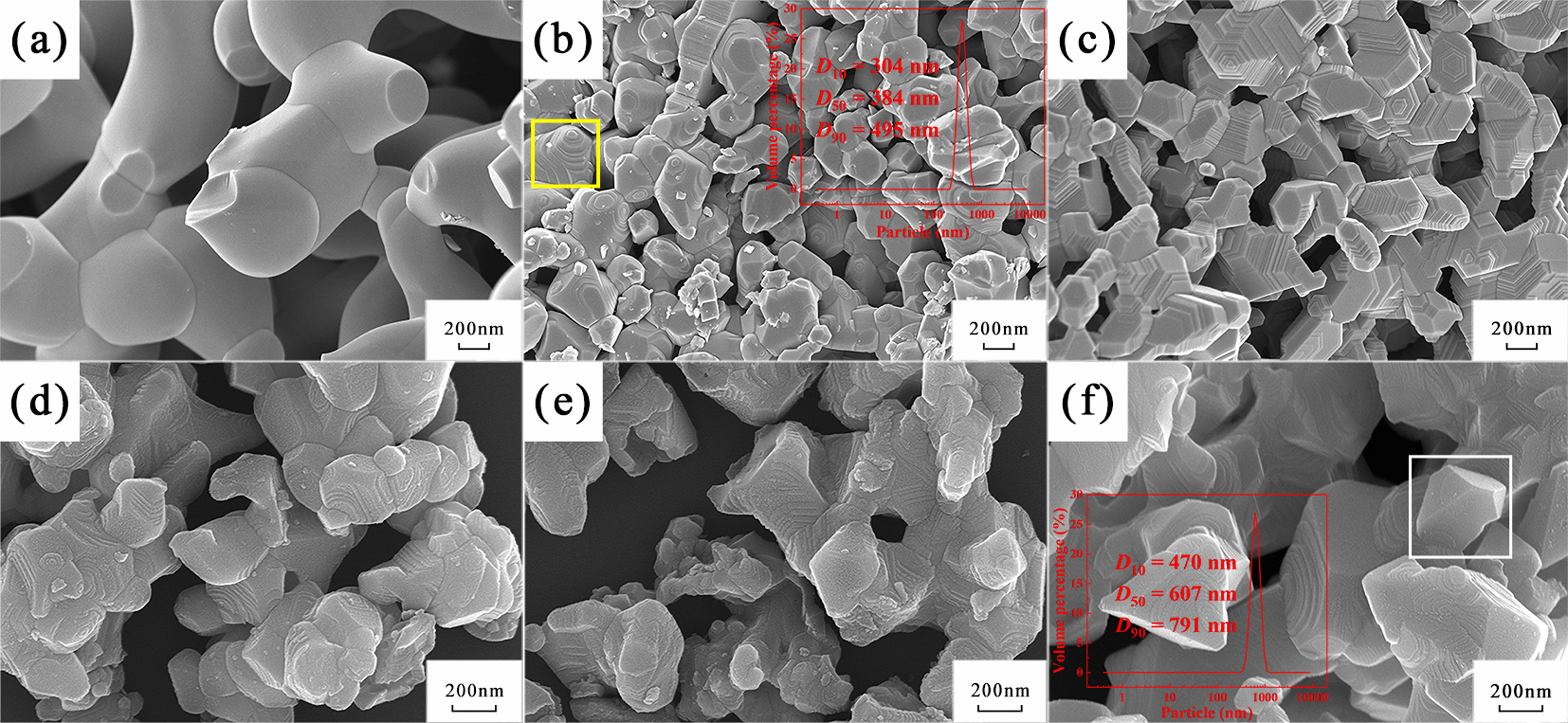
Fig. 6 shows the morphology of the synthesized TiC powders at different C/Ti molar ratios. Coral-shaped TiC particles adhered together with smooth surfaces and relatively flat cross-sections when the C/Ti molar ratio was 2:1 (Fig. 6a). As the C/Ti molar ratio increased to 2.3:1, stepped morphology began to appear on a fraction of the synthesized particles (designated by the yellow box) and also, the interfaces among particles became clearer (Fig. 6b). Meanwhile, TiC particles of the minimum particle size (median particle size ~ 384 nm) were obtained at this molar ratio. The morphology of the powders transformed into a polyhedral structure when the C/Ti molar ratio was 2.5:1 (Fig. 6c). As can be seen from Fig. 6d~f, it could be discovered that, with further increases in the C/Ti molar ratio, the stepped morphology gradually disappeared. Finally, when the C/Ti molar ratio was 3.3:1, TiC particles displayed smooth polyhedral morphology (indicated by the white box in Fig. 6f) with a median particle size of 607 nm.
Analysis suggested that the noticeable variation in the morphology of the synthesized TiC powders with different C/Ti molar ratios was caused primarily by the transformation of the stacking mode of Ti and C atoms owing to different C/Ti molar ratios. TiC is a typical ceramic of face-centered cubic structure, in which the (111) plane has the highest surface atomic density and the lowest surface energy [28]. However, along the [111] direction, ionic bonding is dominant, and Ti atomic layers and C atomic layers are arranged alternately, resulting in a high surface activity of (111) planes. Therefore, the formed TiC particles were preferentially deposited on the (111) crystal planes to maintain the lowest surface energy, and the higher the C/Ti molar ratio, the greater the probability that atoms were deposited on the (111) planes. According to the lowest energy principle, the TiC particles tended to be two-dimensionally arranged on the (111) planes [29, 22]. Simultaneously, the reaction rate was accelerated with the carbon content, which leaded to a phenomenon that the newly formed TiC particles were deposited on the new (111) planes before the previously formed planes were fully paved, and thus resulted in the formation of the stepped morphology. Subsequently, as more and more stacked planes raised the inner energy of the crystals, the later formed TiC particles were preferentially deposited between the steps instead, to reduce the internal energy of the crystal, resulting in the gradual disappearance of the stepped morphology. Finally, when the molar ratio was 3.3:1, some particles with smooth planes could be observed.
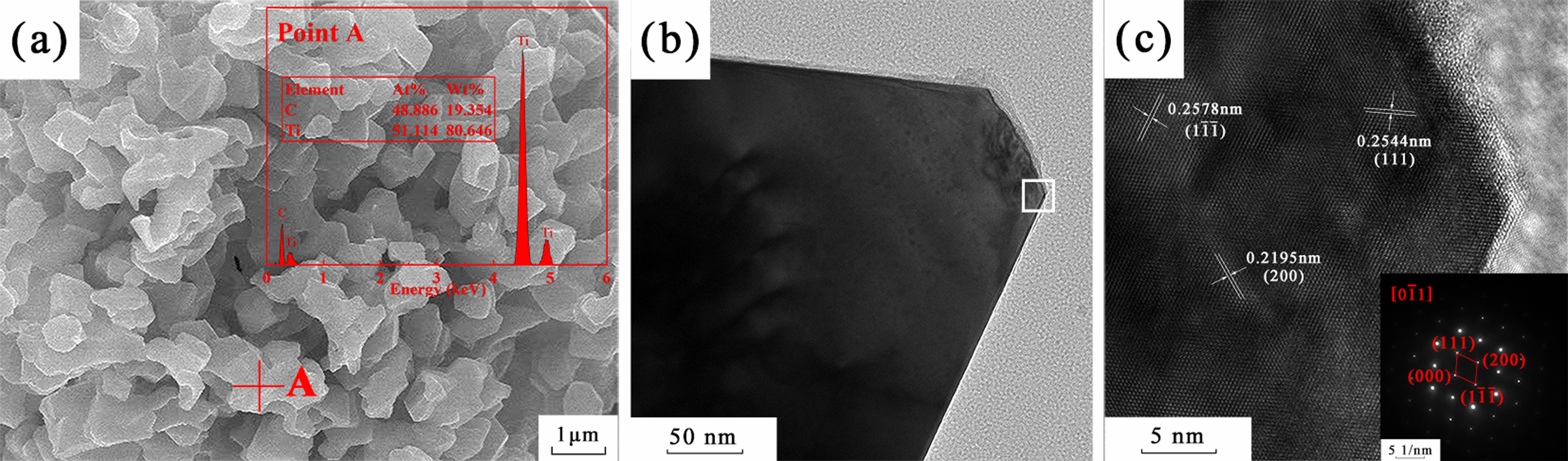
Fig. 7 demonstrates the SEM and TEM images of TiC-3.3 calcined at 1500 ℃ for 30 min. Fig. 7a displayed that Ti and C were the main components, and Oxygen was not detected by the EDS (Point A). Fig. 7c shows the high-resolution and selected electron diffraction pattern at the white box in Fig. 7b. The lattice fringes of the TiC (1 1 1), (100), and (200) planes were labeled in Fig. 7c, which were consistent with the electron diffraction pattern.
Sinterability of the synthesized TiC powder
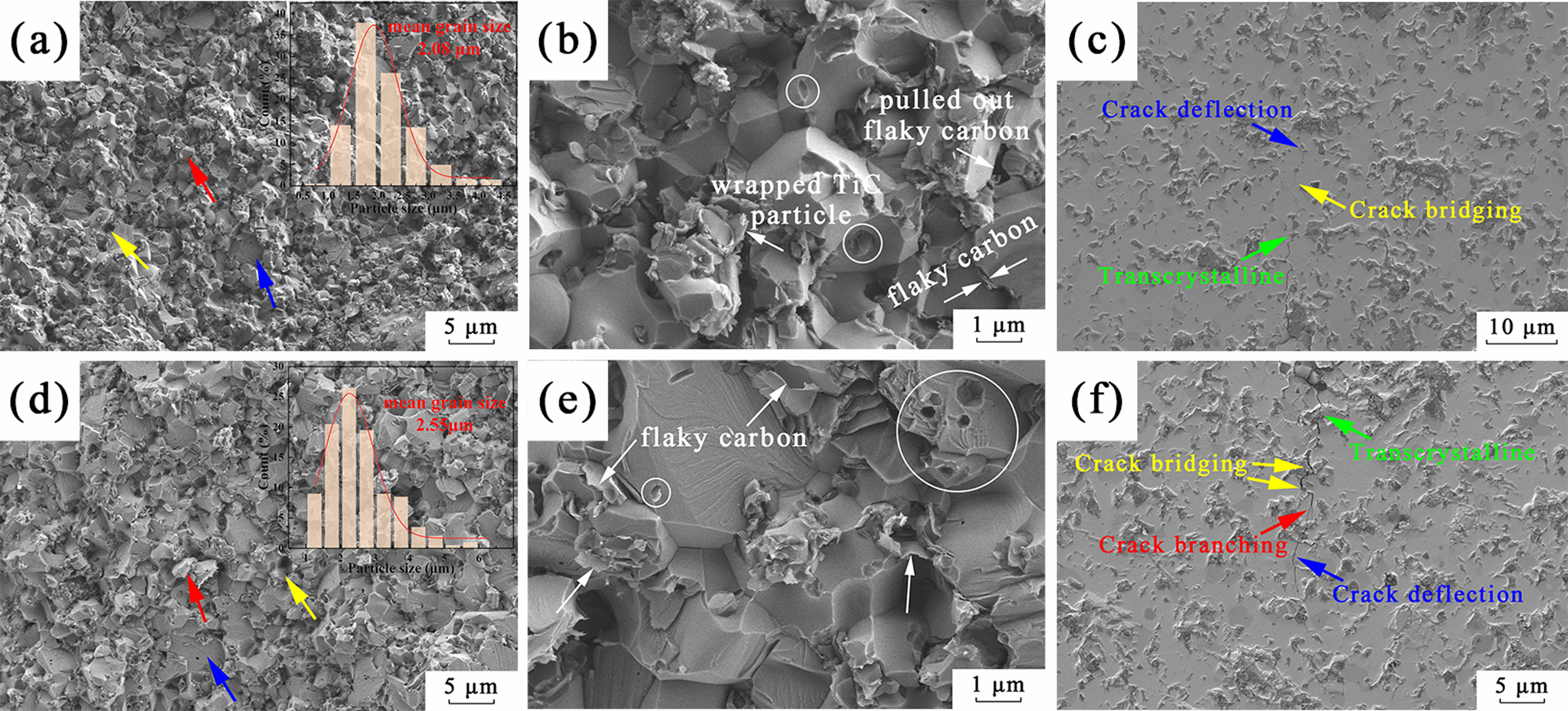
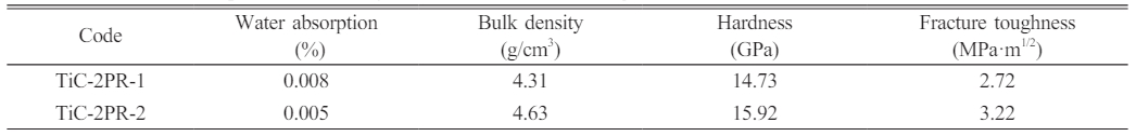
The water absorption, bulk density, Vickers hardness, fracture toughness of the TiC ceramics with TiC-3.3 powder and phenolic resin as the starting powder mixture were summarized in Table 3. The densification and mechanical properties of the TiC ceramics significantly improved with the increase of dwell time. The morphology of the fractured surface (Fig. 8a, 8d) exhibited homogenous grain size (2.08 μm for TiC-2PR-1 and 2.55 μm for TiC-2PR-2) and densified structure. Furthermore, the oxide impurities (TiO2) carried by the obtained TiC powder were purged by the carbonized phenolic resin in the TiC grain boundary, which contributed to improvements in the driving force and the resultant enhancement in the sintering densification of the TiC ceramics [30]. The TiC grains were wrapped by flaky carbon (white arrows in Fig. 8b, 8e), thereby weakening the bond strength at grain boundaries. Therefore, the fracture mode of intergranular fracture (red arrows) and grain pullout (yellow arrows) in addition to predominant transgranular fracture mode (blue arrows) were presented in the fractured surfaces of the obtained TiC ceramics (Fig. 8a, 8d). Some tiny pores (white round) can be observed in the fracture surfaces of the TiC-2PR-1 (Fig. 8b) and TiC-2PR-2 (Fig. 8e), which were caused by the pull-out of the fine TiC grains. When the TiC grains were pulled out, the flaky carbon were stripped or existed in the pore. The crack deflection, crack bridging and transcrystalline were demonstrated in the polished surface of the TiC-2PR-1 (Fig. 8c). In addition to these toughening mechanisms, the crack branching also existed in the TiC-2PR-2 (Fig. 8f). The transformation of the crack propagation mode caused the more tortuous crack propagation path, consumed more crack energy, and as a result, improved the mechanical properties of the TiC ceramics. Compared to the TiC1-2PR-1, the TiC1-2PR-2 embodied higher hardness and fracture toughness, which were up to 15.92 GPa and 3.22 MPa·m1/2, respectively.
|
Fig. 1 XRD pattern of the carbonized phenolic resin |
|
Fig. 2 (a, b) TEM and (b) HRTEM images of the carbonized phenolic resin. |
|
Fig. 3 XRD patterns of TiC powders synthesized in different conditions: (a) 2:1, 1400-1500 ℃, 30 min, (b) 2:1, 1500 ℃, 15-30 min, and (c) 2:1-3.3:1, 30 min, and (d) the detailed plot in the 41-43° range. |
|
Fig. 4 Rieveld fitting patterns TiC-3.3 obtained at 1500℃ for 30 min. |
|
Fig. 5 (a) XPS spectrum of TiC-3.3 sample calcined at 1500 ℃ for 30 min and fitted XPS spectra related to (b) Ti 2p, (c) O 1s, (d) C 1s. |
|
Fig. 6 SEM images and particle size distribution of TiC powders synthesized at 1500 ℃ for 30 min at the molar ratio of (a) 2:1, (b) 2.3:1, (c)2.5:1, (d) 2.8:1, (e) 3:1, and (f) 3.3:1, respectively. The stepped and polyhedral morphology were designated by the yellow box in (b) and the white box in (f), respectively. |
|
Fig. 7 (a) SEM and (b, c) TEM image of sample TiC-3.3 calcined at 1500 ℃ for 30 min. |
|
Fig. 8 Microscopic morphologies of the fractured and polished surfaces of the TiC ceramics. (a~c) and (d~f) corresponded to TiC2PR-1 and TiC-2PR-2, respectively. |
|
Table 2 Total carbon and oxygen contents of TiC-2.3 and TiC-3.3 synthesized at 1500 ℃ for 30 min. |
|
Table 3 The water absorption, bulk density, hardness, and fracture toughness of the obtained TiC ceramics. |
Titanium carbide powders were successfully synthesized by the carbothermal reduction of TiO2 using phenolic resin-derived pyrolysis carbon as a carbon source. With the increase of the C/Ti molar ratio, the purity and particle size of the synthesized TiC powders were gradually increased, and the morphology transformed from coral shape to polyhedral structure. The TiC powder with median particle sizes of 384 and 607 nm was synthesized at 1500 ℃ for 30 min when the C/Ti molar ratios were 2.3:1 and 3.3:1, respectively. TiC-3.3 powder exhibited good sinterability. The hardness and fracture toughness of the TiC ceramic sintered at 2000 ℃ under 40 MPa with a dwell time of 2 h reached 15.92 GPa and 3.22 MPa·m1/2, respectively.
The authors gratefully acknowledge the financial support from the National Natural Science Foundation of China (No. 51662018 and 51962011), State Key Laboratory of New Ceramic and Fine Processing Tsinghua University (No. KF202311), Project of Jingdezhen Science and Technology Bureau (No. 20224GY008-04), and Jiangxi Provincial Postgraduate Innovation Fund (No. YC2022-s904).
- 1. A. Rajabi, M.J. Ghazali, A.R. Daud, Mater. Des. 67 (2015) 95-106.
-

- 2. B.X. Dong, F. Qiu, Q. Li, S.L. Shu, H.Y. Yang, Q.C. Jiang, Nanomaterials 9[8] (2019) 1-40.
-
- 3. M. Ali, Z. Muayaduldeen, J. Ceram. Process. Res. 16[5] (2015) 1-5.
- 4. J.H. Lee, H.K. Park, J. Ceram. Process. Res. 22[5] (2021) 590-596.
-
- 5. W. Sen, H.Y. Sun, B. Yang, B.Q. Xu, W.H. Ma, D.C. Liu, Y.N. Dai, Int. J. Refract. Met. Hard Mater. 28[5] (2010) 628-632.
-
- 6. Z. Xie, Y. Deng, Y.Y. Yang, H. Su, D.L. Zhou, C. Liu, W.Z. Yang, RSC. Adv. 7 (2017) 9037-9044.
-
- 7. J.L. Hu, H.N. Xiao, P.Z. Gao, Q. Li, W.M. Guo, J. Ceram. Process. Res. 14[1] (2013) 77-81.
-
- 8. P.J. Li, E.G. Kandalova, V.I. Nikitin, A.G. Makarenko, A.R. Luts, Y.F. Zhang, Scr. Mater. 49[7] (2003) 699-703.
- 9. L. Yu, W.J. Ji, S.W. Zhang, Y. Song, H. Liu, Z.F. Wang, Q. Liu, X.H. Wang, Ceram. Int. 46[16] (2020) 25485-25492.
-
- 10. M. Song, Y.F. Yang, M.Q. Xiang, Q.S. Zhu, H.D. Zhao, Powder Technol. 380 (2021) 256-264.
-
- 11. H.Y. Sun, X. Kong, W. Sen, G.Y. Liu, Z.Z. Yi, Adv. Mater. Res. 1089 (2015) 142-146.
-
- 12. K.H. Wu, G.H. Zhang, H.P. Gou, K.C. Chou, Vacuum 151 (2018) 51-60.
-
- 13. K.H. Tang, A.L. Zhang, T.J. Ge, X.F. Liu, X.J. Tang, Y.J. Li, Mater. Today. Commun. 26 (2021) 101879.
-
- 14. Y.F. Gu, J.X. Liu, F.F. Xu, G.J. Zhang, J. Eur. Ceram. Soc. 37[2] (2017) 539-547.
-
- 15. S.S. Tzeng, Y.G. Chr, Mater. Chem. Phys. 73[2-3] (2002) 162-169.
-
- 16. D.S. Kang, S.M. Lee, S.H. Lee, J.S. Roh, Carbon Lett. 27 (2018) 108-111.
-
- 17. H.C. Oh, S.H. Lee, S.C. Choi, Int. J. Refract. Met. Hard Mater. 42 (2014) 132-135.
-
- 18. W. Luo, Y.X. Wang, S.L. Chou, Y.F. Xu, W. Li, B. Kong, S.X. Dou, H.K. Liu, J.P. Yang, Nano Energy 27 (2016) 255-264.
-
- 19. M. Zhao, H.H. Song, X.H. Chen, W.T. Lian, Acta Mater. 55[18] (2007) 6144-6150.
-
- 20. Z.X. Zheng, G.J. Liang, L. Li, J. Liu, X.B. Wang, Y. Sun, K. Li, Gels 8[5] (2022) 308.
-
- 21. F.K. Lin, X.G. Zhang, X.J. Liu, Y.F. Xu, Z.H. Sun, L.P. Zhang, Z.H. Huang, R.Y. Mi, X. Min, Polymer 228 (2021).
-
- 22. A. Heidarpour, H. Aghamohammadi, R. Jamshidi, S. Ghasemi, Ceram. Int. 45[4] (2019) 4653-4660.
-
- 23. J.E. Oghenevweta, D. Wexler, A. Calka, Mater. Charact. 140 (2018) 299-311.
-
- 24. Y.J. Wang, H. Deng, C.L. Ye, K. Hu, K. Yan, J. Alloys Compd. 775 (2019) 348-352.
-
- 25. S.J. Guan, L. Hao, Y.Q. Yang, H. Yoshida, and X.W. Zhao, Y. Lu, J. Solid State Electrochem. 25[2] (2020) 603-609.
-
- 26. M. Ivanovskaya, E. Ovodok, D. Kotsikau, I. Azarko, M. Micusik, M. Omastova, V. Golovanov, RSC. Adv. 10 (2020) 25602-25608.
-
- 27. I.W. Almanassra, Y. Zakaria, V. Kochkodan, K. Mroue, A. Zekri, M.A. Atieh, T. Al-Ansari, J. Therm. Anal. Calorim. 147 (2022) 11787-11803.
-
- 28. S.B. Jin, P. Shen, B.L. Zou, Q.C. Jiang, Cryst. Growth Des. 9[2] (2009) 646-649.
-
- 29. S.B. Jin, P. Shen, Q.L. Lin, L. Zhan, Q.C. Jiang, Cryst. Growth Des. 10[4] (2010) 1590-1597.
-
- 30. M. Zhu, J. Chen, F.F. Li, C.C. Huang, H. Liu, X.J. Liu, Z.R. Huang, Ceram. Int. 49[7] (2023) 11504-11512.
-
 This Article
-
2024; 25(2): 212-219
Published on Apr 30, 2024
- 10.36410/jcpr.2024.25.2.212
- Received on Nov 16, 2023
- Revised on Dec 8, 2023
- Accepted on Dec 11, 2023
Services
- Abstract
introduction
experimental procedures
results and discussion
conclusion
- Acknowledgements
- References
- Full Text PDF
Shared
Correspondence to
- Hongkang Wei
-
Advanced Ceramic Materials Research Institute, School of Materials Science and Engineering, Jingdezhen Ceramic University, Jingdezhen, Jiangxi 333403, People’s Republic of China
Tel /Fax: +86-798-8499678 - E-mail: weihongkang@jcu.edu.cn
Clean-Energy Research Institute(CRI), Hanyang University, 222, Wangsimni-ro, Seongdong-gu, Seoul, 04763, Korea
E-mail: jcpr@hanyang.ac.kr