


- Impact of incorporating Gr particles in dielectric fluid on machining performance of AA7050/SiC/Al2O3 hybrid composites
A. Vishnua,* and M. Subramanianb
aAssistant Professor, Department of Mechanical Engineering, Nandha Engineering College, Erode – 638052
bDepartment of Mechanical Engineering, Sns College of Technology, Coimbatore, Tamilnadu, IndiaThis article is an open access article distributed under the terms of the Creative Commons Attribution Non-Commercial License (http://creativecommons.org/licenses/by-nc/4.0) which permits unrestricted non-commercial use, distribution, and reproduction in any medium, provided the original work is properly cited.
This study attempted to machine AA7050 using the Electric Discharge Machining (EDM) technique fabricated through stir casting, whereas aluminium oxide and silicon carbide particles were used as reinforcement. Experiments conducted by altering, powder concentration, current, pulse duration, and reinforcing %, machining performance evaluated in terms of material removal rate (MRR), Tool Wear Rate (TWR), surface roughness (Ra), and Machined Surface Hardness (MSH). Because of the high density, the suspension of Gr particles inside the spark gap was obstructed, causing particle deposition over the surface, which lowers the MRR in contrast to other particle suspensions. Lower heat was produced at higher Tons due to plasma densification, resulting in a drop in TWR. The Ra value improved as a result of the electrode’s higher gap distance from the workpiece, which enables thorough flushing of machined waste. The incorporation of particles also evenly distributed the energy over the machined area, eliminating the uneven machined surface. Black patches, resolidified solids, globules, craters, and pits were seen on the surface topography, when particles were introduced to the dielectric fluid, these defects were eliminated because of complete flushing of machined debris.
Keywords: PMEDM, Hybrid composites, Surface topography, Stir casting, Hardness.
Because of its excellent strength to weight ratio, aluminium matrix composites (AMC) have found application in the aircraft industry. Particles used as reinforcing materials includes: carbon nanotubes (CNT), graphite, boron carbide (B4C), aluminium oxide (Al2O3), silicon carbide (SiC), and [1-3]. There are several techniques for making composites, with stir casting being the most effective for mass production [4-6]. These techniques include compo casting, squeeze casting, powder metallurgy, and stir casting. Different stir casting factors such as melting temperature, flux, preheating temperature, stirring speed, and stirring length control the uniform distribution of composites [7, 8]. When composites are machined using conventional machining techniques, it results in increased tool wear, the formation of build-up edges, and a deterioration in surface quality [9, 10]. To alleviate the problem, it is advised that the composites be machined utilizing unconventional machining processes. Ultrasonic machining, abrasive jet machining, plasma arc machining, laser beam machining, and electric discharge machining (EDM) are a few examples of the uncommon machining techniques. EDM produced components with a high degree of precision and accuracy [11-14].
The following are the main process variables that impacts the machining performance. The process variables which have effect on the output quality of the machining process are current, pulse off time, pulse on time, gap distance, polarity, tool materials, and dielectric medium [15, 16]. The discharge current was the most significant component, and it was stated that the quantity of spark energy produced is dependent on the current’s parametric value [17]. The largest energy is created in the machining zone by increased current and pulse on time, which enhance MRR. Incomplete flushing happens and the MRR is decreased when the pulse off time is short [18]. Surface roughness appears to differ nonlinearly when peak current varies and continues to climb as pulse on time increases [19]. The best surface quality obtained by using the lowest feasible pulse-on, pulse-off, and nominal-value input current. Incorporation of foreign particles viz (Al2O3, Cu, SiC, Gr) improves the EDM performance [20-23]. The electrified particles enable a more even dispersion of energy under PMEDM conditions, which enhances surface quality [24]. The surface quality was revealed to be improved when powder particles were combined with the dielectric
fluid, eliminating micro fractures and craters [25]. Incorporation of finer particles provides best surface finish, and MRR improves until the optimal concentration beyond that it decreases because of insufficient flushing [26]. Al2O3 particles had a low heat conductivity of 29 w/mk, which contributed to the decrease in MRR that followed their inclusion [27]. The inclusion of graphene particles improves the dielectric’s insulating properties, increasing the spark gap [28]. The addition of powder particles to the dielectric fluid is one of the experiments that researchers have documented. The machining of AA7050/SiC/Al2O3 hybrid composites, however, was poorly understood. The objective of this study was to investigate the machining properties of hybrid composites consisting of AA7050/SiC/Al2O3 hybrid composites by incorporating Gr in the dielectric fluid. The experimental runs were set up using the Taguchi mixed orthogonal array, and surface topography was examined using a SEM.
An aluminium alloy (AA7050) containing SiC and Al2O3 reinforcement was produced using the stir casting technique, and its average reinforcement particle size was 5 µm. A kilogram of AA7050 was heated to 850 degrees Celsius in a graphite crucible. In order to get rid of the moisture, the strengthening grains were heated to a temperature of 250 oC before being added to the melt. A 1000 rpm speed was used to stir the mixture for 180 seconds. To increase the composites’ wettability, magnesium (Mg) powder was added as flux. The melt was stirred for 120 seconds after flux addition. The permanent die steel mould, which had the dimensions 102 mm×102 mm×6.25 mm (L×B×T), was warmed before pouring the molten metal. The composites were then taken out of the mould after the die cooled for 24 hours. To eliminate surface flaws, the produced composites were rotated and faced to a size of 100 mm×100 mm×6 mm.
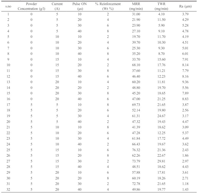
Using wire cut EDM, the produced composites were cut to specimen size of 25 mm×6 mm×6 mm. To increase the machining capabilities of hybrid composites, Gr particles in various concentrations were introduced to the dielectric medium. A separate tank with measurements of 400×240×200 mm and a capacity of 10 litres was constructed using mild steel that was 3 mm thick and equipped with a motorized stirrer for mixing the powder particles. Die sink EDM experiments were conducted by varying the quantity of Gr powder, the percentage of reinforcement, the Ton, and the current. According to Table 1, the parameters were modified for four levels while the powder concentration was varied for two levels. Table 2 displays the outcomes of the 32 experiments utilizing the Taguchi orthogonal array for MRR, TWR, MSH, and Ra responses. The samples were machined for 300 seconds. According to Equations 1 and 2, MRR and TWR was determined, it was the weight difference before and after machining to the machining time.
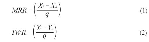
Whereas
Xb and Xa – before and after milling, the sample’s weight
Yb and Ya – before to and following machining, the electrode’s weight
q – Machined time
Using a surface roughness tester made of Mitutoyo SJ210 with a 5% accuracy, the Ra was computed. The Ra was calculated at 5 distinct locations, and the average value taken as a measure of surface roughness. The MSH value was calculated at 10 different locations on the machined surface. The specimens were subjected to hardness testing in accordance with ASTM E-18-05 standards, with a 100 kg weight applied and a dwell time of 5 seconds.
|
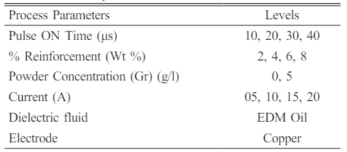
Table 2 Experimental results of AA7050 hybrid composites machined under Gr incorporated dielectric fluid. |
Material Removal Rate
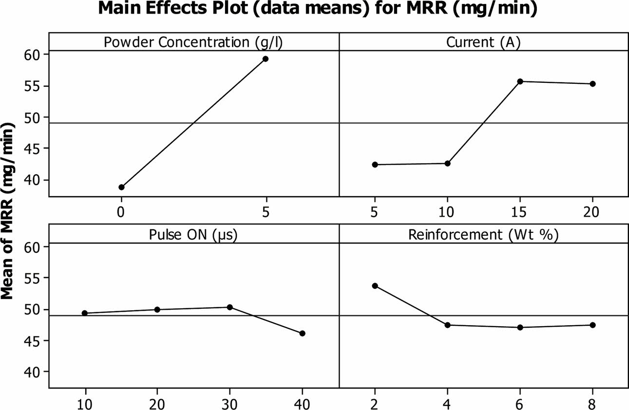
Figure 1 shows the effects of distinct input variables on the MRR of hybrid composites made using Gr powder and mixed EDM. the dielectric fluid after the addition of 5 g/l Gr particles, mean MRR of 59.31 mg/min was attained which was 3.6% and 9.7% lesser than the Al2O3 and SiC incorporated PMEDM [29]. In comparison with unmixed dielectric fluid a 35% improvement in MRR was recorded. As discussed by distinct researchers when The bridging action caused the powder particles to be integrated sparking occurs more frequently which faciltates the formation of spark with high heat intensity [30], hence MRR increases. In comparison with other powders incorporation of Gr particles inhibits lower MRR because of its higher density [31]. The high density of Gr particles hindered the spark gap. which causes deposition of particles across the surface and reduces MRR. When the current value was set to 15A, the highest MRR of 55.71 mg/min was reached. As the current was increased to 20A, the MRR marginally decreased to 55.23 mg/min. Superior intensity heat produced by higher current discharge boosts the MRR of hybrid composites [32].
Mean MRR slightly increases from 49.44 mg/min to 50.34 mg/min, when there is increase in Ton from 10 µs to 30 µs, thereafter it declines drastically to 46.09 mg/min for the Ton of 40 µs. The results revealed that the plasma densification occurred [33] when the Ton was set to the 1940s. Up until the 1930s, the created plasma channel was dispersed evenly throughout the surface, which raises the MRR [34]. When the reinforcement concentration was reduced to 4wt percent, the maximum MRR for machined hybrid composites containing 2 wt percent reinforcing particles fell to 47.5 mg/min from 53.79 mg/min. Since 47.5 mg/min was recorded for composites with 6 and 8% reinforcement content, respectively, further increasing the composite weight proportion had no impact on the MRR of hybrid composites.
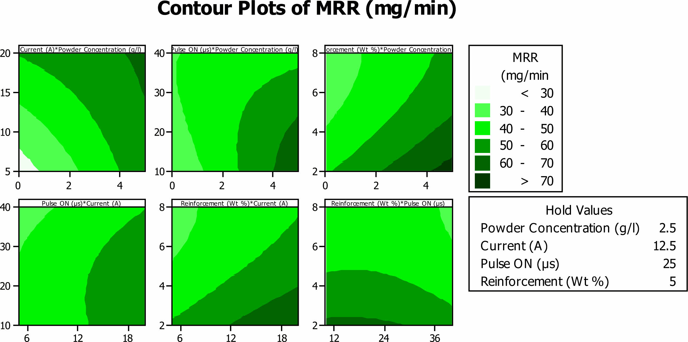
The interactions between various input components and composite MRR are depicted in Fig. 2. MRR for AA7050/2Al2O3/2SiC hybrid composites was measured to be 61.64 mg/min when the Ton value was set to 10 s; however, when the Ton value was increased to 40 μs, it decreased to 54.69 mg/min. MRR was 43.42 mg/min when AA7050/8Al2O3/8SiC was machined at 10A Ton; when the Ton was increased to 40 μs, the MRR fell to 38.52 mg/min. MRR decreased as current increased owing to plasma densification. When the AA7050/2SiC/2Al2O3 hybrid composites were machined at a lower parametric value of 5A current, the MRR was 51.07 mg/min, which rose to 69.81 mg/min when the current was increased to 20A. MRR was lowered to 37.26 mg/min and 49.42 mg/min for the present 5A and 20A AA7050/8SiC/8Al2O3 hybrid composites.
A minimum MRR of 39.97 mg/min was achieved at 10 μs Ton and 5 A current when the electric process settings were altered. A 30% improvement in MRR was seen when the Ton value was held at 10 μs while the current value was increased to 40A. MRR was lowered to 49.44 mg/min when both parameters were set to their maximum values of 40 μs and 20A, however. The decrease in Material Removal Rate (MRR) as the weight percentage of composites increases can be attributed to several factors, including the non-conductive behavior of reinforcing materials. As the weight percentage of composites rises, the volume of non-conductive materials (like graphite) within the composite tool also increases. These non-conductive materials do not contribute to the electrical discharge machining (EDM) process and can inhibit the efficient removal of material. The reduced electrical conductivity of the composite tool due to the higher content of non-conductive materials leads to weaker and less effective discharges, resulting in a decrease in MRR. Therefore, the non-conductive behavior of reinforcing materials hinders the overall EDM performance, especially at higher weight percentages. MRR sharply rises when 5 g/l of Gr particles are added to the dielectric fluid. When hybrid composites with 2 wt% reinforcing particles were machined in a mixed dielectric environment with 5 g/l of Gr, a maximum MRR of 73.22 mg/min was achieved. When the composites with an 8 wt% reinforcement content were machined, MRR was substantially decreased to 52.30 mg/min under the same parametric condition. At a powder-mixed state, the MRR for Ton decreases as Ton increases. A MRR of 31.23 mg/min was achieved for the Ton 10 μs that were machined in unmixed dielectric media, but when Gr particles were introduced, the MRR increased by 53%. MRR significantly decreases to 46.37 mg/min and 39.49 mg/min for unmixed and PMEDM dielectric conditions, respectively, at a higher parametric value of 40 μs. The maximum MRR for current at PMEDM was reached for 40A and decreased to 50.40 mg/min in pure dielectric medium. The extremely low MRR of 25.20 mg/min for lower parametric values of 5A current was increased to 56.09 mg/min when the powder particles were added to the dielectric fluid. Higher Gr particle densities can lead to improved MRR due to enhanced thermal conductivity and efficient debris flushing. However, excessively high densities may result in decreased MRR as agglomeration and conductivity saturation occur. In practical use for the stir casting process, controlling Gr particle density is crucial to achieve the desired balance between improved MRR and process efficiency. Optimizing the Gr powder density can enhance the performance of composites in EDM while avoiding potential drawbacks associated with extreme density levels.
Tool Wear Ratio
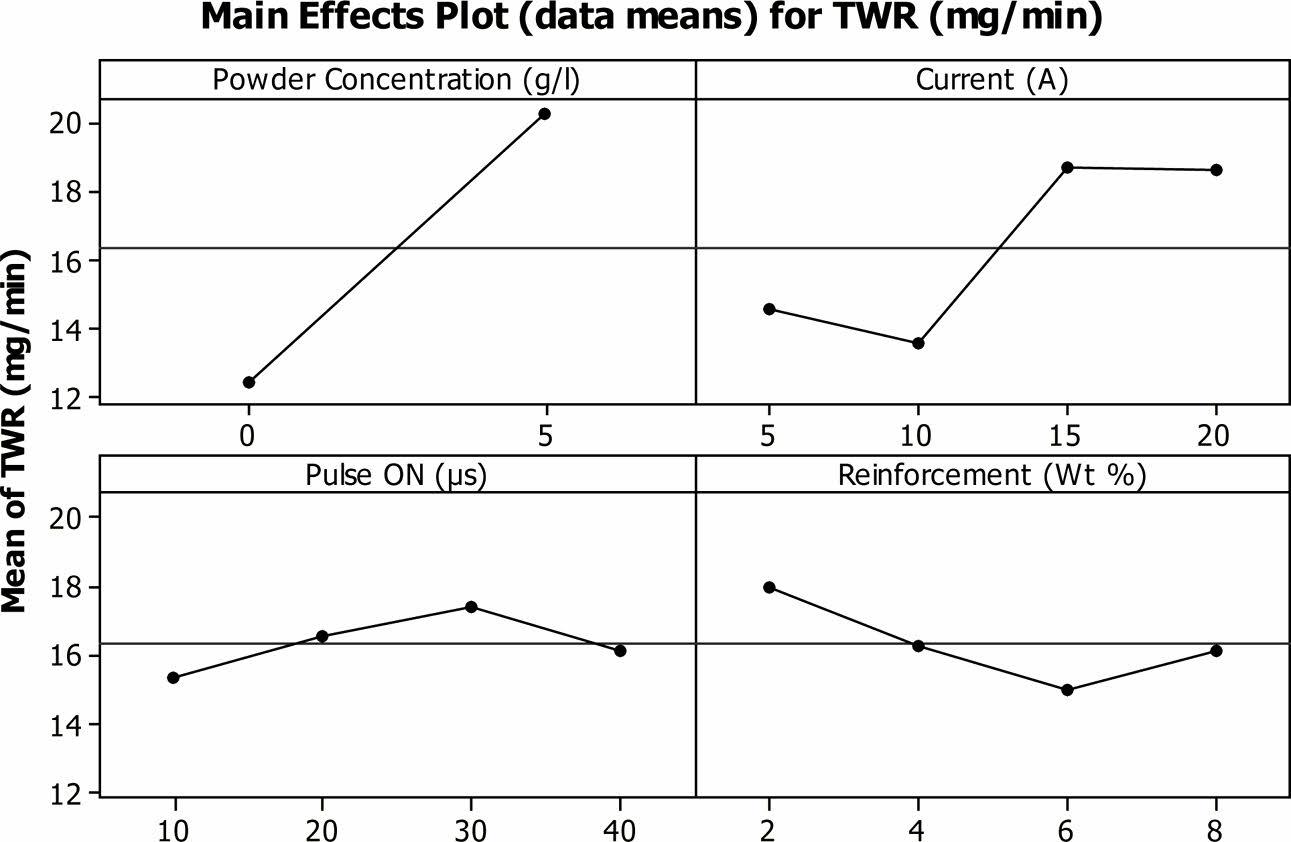
The TWR of AA7050 hybrid composites is affected by several process variables, as shown in Fig. 3. The addition of the powder particles resulted in a TWR of 20.325 mg/min, which was 6% higher than the TWR under unmixed circumstances [35]. Bridging effect refers to the movement of integrated powder particles in a zigzag pattern as a result of the application of voltage [36]. Owing to which high heat was generated hence TWR increases. The TWR attained under Gr particle incorporated dielectric medium was 3.7% higher and 28% lower than Al2O3 and SiC incorporated dielectric medium respectively [37]. The higher TWR in the presence of Graphite (Gr) particles compared to Alumina (Al2O3)-incorporated medium was attributed to the electrical and thermal conductivity properties of Gr. Gr’s enhanced electrical conductivity can result in more intense discharges, which can lead to increased erosion of the tool, consequently raising TWR. The favorable dielectric properties, improved heat dissipation, and stable spark channel offered by Gr-incorporated dielectric medium make it a more suitable choice for reducing TWR in EDM compared to SiC-incorporated medium. These factors contribute to the observed 28% lower TWR when using Gr as the dielectric medium.
The TWR rises until it reaches the 15A saddle point, after which no change was seen. With increase in current, intensity of the discharge upsurges which produces the high heat owing to which TWR increases [38]. Similar observation was noticed in the experimental results of MRR. The TWR rises as Ton is raised until a saddle point of 30 μs, at which time it begins to fall. Due of the plasma densification, less heat was produced at greater tonnage, which decreased TWR [39]. When AA7050/6Al2O3/6SiC hybrid composites were machined in a pure dielectric medium, the lowest TWR was attained. According to the experimental findings, the majority of the heat generated during the machining of composites containing 6 wt% was transmitted to the workpiece; as a result, the maximum MRR was observed for the same parametric condition.
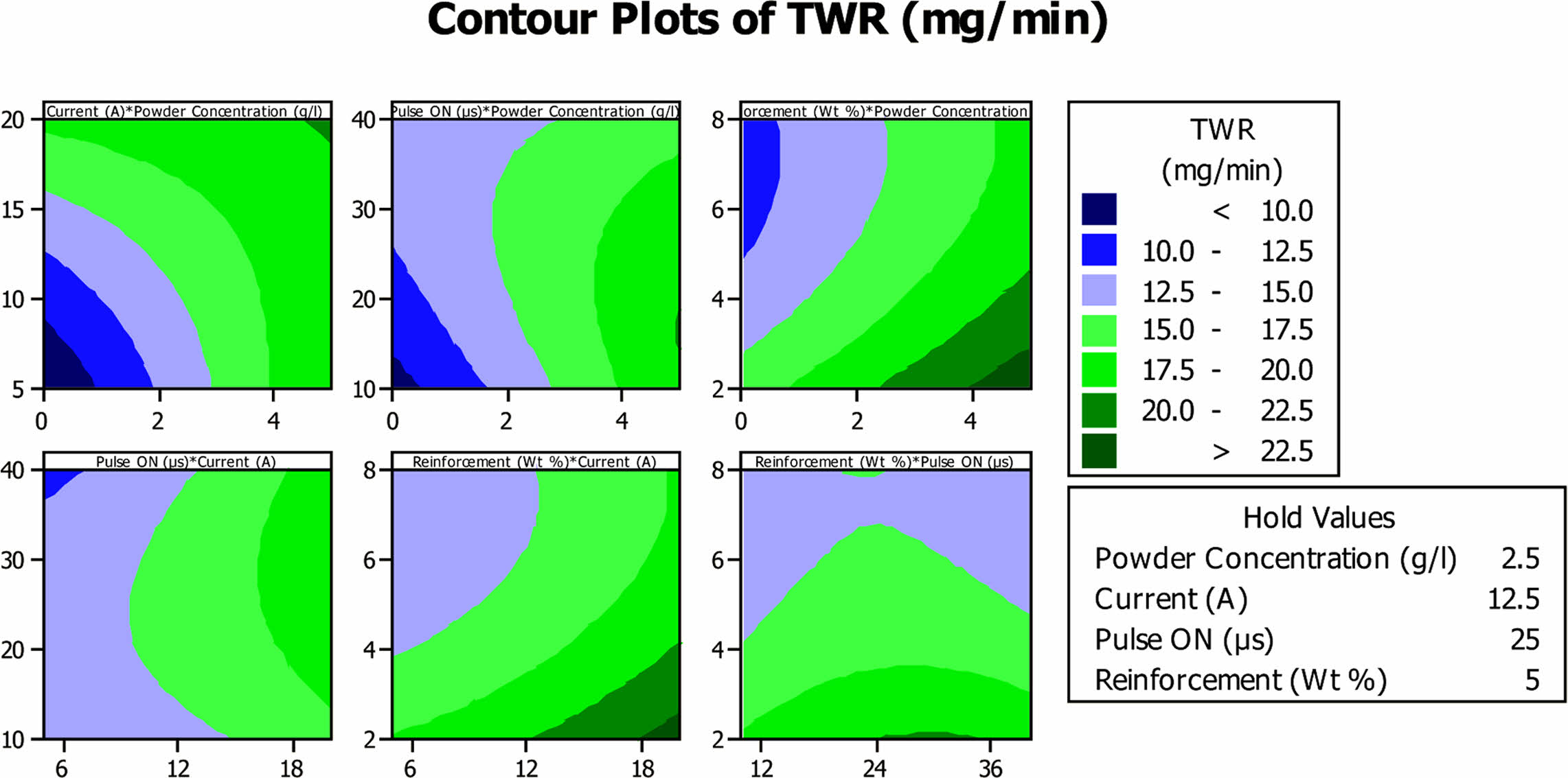
As seen in Fig. 4, the Ton and reinforcement coalition effect on TWR has very little influence. A TWR of 17.78 mg/min was noted when the AA7050 hybrid composites were machined at the Ton of 10s with 2 wt% of reinforcing content, and it was decreased to 14.07 mg/min when the weight percentage of reinforcing material was increased to 8 wt%. TWR of 19.54 mg/min was seen for 2 weight percent reinforced composites with an increase in Ton to 40 μs, and it decreased to 13.13 mg/min when the alloy was reinforced with 8 weight percent of reinforcing particles. TWR of 17.62 mg/min was achieved while machining composites with less reinforcing material at 5A current, and it dramatically increased to 23.45 mg/min at 20A current. For the AA7050/8Al2O3/8SiC composites that were machined, the TWR was reduced to 13.25 mg/min for 5A current and 17.71 mg/min for 20A current, respectively. TWR was decreased because increased current produced more heat, which was transferred to the work piece rather than the electrode material [40].
When the electric process parameters were tuned at lower lowels i.e 10 µs and 5A, minimum TWR of 13.17 mg/min was attained. Concurrent increase of current and Ton to 40 µs and 20A, a 30% raise in TWR was observed. TWR of 17.62 mg/min was achieved while machining composites with less reinforcing material at 5A current, and it dramatically increased to 23.45 mg/min at 20A current. For the AA7050/8Al2O3/8SiC composites that were machined, the TWR was reduced to 13.25 mg/min for 5A current and 17.71 mg/min for 20A current, respectively. TWR was decreased because increased current produced more heat, which was transferred to the work piece rather than the electrode material. The findings showed that PMEDM was compatible with achieving the lowest TWR when machining hybrid composites with more reinforcing material.
The hybrid composites were machined at lower Tons of 10 in an unmixed dielectric medium and this produced the lowest TWR of 8.88 mg/min. When the same parametric parameters were satisfied and 5 g/l of powder particles were introduced to the dielectric fluid, the TWR rose to 19.85 mg/min. When the parametric value of Ton was increased to 40 μs, the TWR for the powder-mixed and unmixed dielectric conditions, respectively, was 16.42 mg/min and 13.02 mg/min. When the parametric value of the current was increased to 20A, it climbed to 17.99 mg/min from the minimum TWR of 7.83 mg/min achieved at 5A under unmixed conditions. When the value of current increased from 5A to 20A respectively under PMEDM conditions, a decrease in 10%TWR was noted.
Surface Roughness
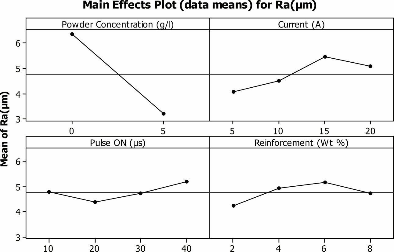
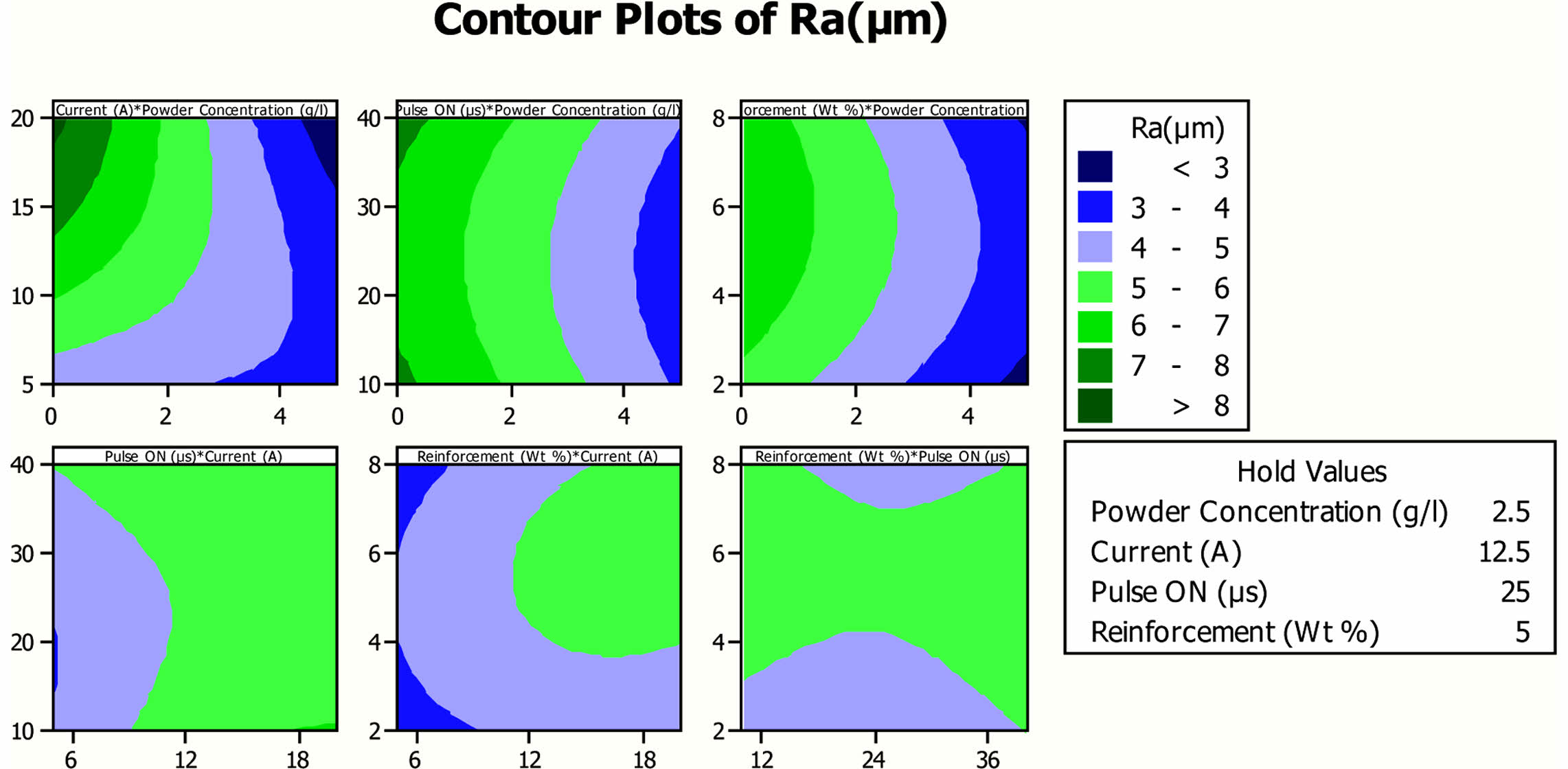
The effect of different process parameters on the Ra on hybrid composites is seen in Fig. 5. The Ra of the composites increased noticeably when the Gr particles were introduced to the dielectric fluid [41]. The inclusion of Gr particles decreased the mean Ra value, which was 6.33 μm under unmixed conditions and 3.20 μm under mixed conditions. The finished machined surface outperformed the surfaces created by adding SiC and Al2O3 particles, respectively, by 56% and 12% [42]. The following facts were used to explain the improvement in the Ra value: (i) The distance between the electrode and the work piece rises due to the bridging effect to maintain the spark gap, which makes it easier to completely flush out the machined debris [43]. (ii) Incorporation of particles uniformly distributed the energy over the machined area which eliminates the un even machined surface [44].
Up until the 15A saddle point, the Ra value rises with an increase in current before falling. Higher current caused more intense sparks to be produced, which in turn caused the machined surface to become cratered and cracked, raising the Ra of the composites. Because of the densification of the plasma, current Ra decreases with larger parametric values [45]. The minimum Ra was achieved when machined with Ton of 20 µs there after Ra trends to increase. When raised the Ton beyond 20 µs spark hinged in for extra duration which removes a more materials which initiates the machined debris densification [46]. Due to the fact that the material was not entirely washed away, a remelted layer forms on the surface, increasing Ra. The hybrid composites made of AA7050, Al2O3, and SiC had the lowest Ra, measuring 5.16 μm. According to the experimental findings, while machining composites with 6 wt% reinforced particles, the maximum MRR and lowest TWR were observed. It was clear that maximum heat was generated and transferred to workpeice which cause deeper craters on the work piece hence Ra decreases.
With an increase in the weight percentage of the reinforced material, the machined Ra of composites decreases. When the composites with 2 wt% were machined, a Ton Ra of 4.42 μm was seen at 10 μs, and it rose to 5.36 μm when the reinforcement weight content was raised to 8%, as shown in Fig. 6. 4.99 μm and 5.09 μm were measured for the composites with weight percentages of 2 and 8, respectively, at greater tonnages of 40 μs. The hybrid composites of AA7050/6Al2O3/6SiC were made with the lowest quality machined surface of 6.61 mm. No divergence in Ra value was seen when the weight fraction of the reinforced particles increased at lower parametric values of 5A current.
For AA7050/2SiC/2Al2O3 hybrid composites Ra value slightly increases from 3.42 µm to 4.09 µm if there is a current increase from 5A to 20A. The Ra value for the identical parametric condition increases from 3.42 µm to 5.14 µm for the composites with 8 wt% weight proportion. The results revealed that to attain the best surface quality it was essential to machined with lower parametric value of current. Gr particles in the dielectric medium act as a solid lubricant, enhancing the flushing efficiency of machined debris, preventing remelting, and promoting smoother material removal. The presence of Gr particles, in the dielectric medium improves the flushing efficiency and aids in reducing the friction and adhesion between the workpiece and debris. This, in turn, promotes smoother and more efficient material removal, resulting in a finer surface finish and reduced surface irregularities.
At lower electric parametric level of 5A current and 10 µs Ton, Ra of 4.05 µm was attained. By holding the current at 5A Ra value increases to 5 µm with increase in Ton to 40 µs from 10 µs. In unmixed dielectric media, Ra values of 5.70 μm and 6.58 μm were achieved when AA7050/2Al2O3/2SiC hybrid composites were machined. When the reinforcement content was raised to 8 wt%, these values rose to 6.58 μm and 6.58 μm, respectively. An enormous improvement in Ra was made when powder particles at a concentration of 5 g/l were added. Under PMEDM condition, composites with 2 wt%.
The machined surface of composites displays extremely poor surface quality at lower tons of 10 μs under unmixed conditions (7.19 μm), and it marginally improved at higher tons of 40 μs (7.30 μm). Ra was reported to be 3.58 μm when the powder less particles were added to the dielectric fluid per ton 10 μs, and it increased to 4.04 μm at a higher Ton of 40 μs. From the findings, it was deduced that, regardless of the weight of reinforcement particles included in the composites, adding powder particles and machining at lower Ton leads in higher surface quality. The Ra of the hybrid composites, is more significantly impacted by the interplay between current and powder concentration. For the lower parametric value of current Ra, which was adjusted at 20A, under pure dielectric medium, it was noticed that Ra was 4.43 μm, but it was dramatically enhanced to 8.20 μm. Ra decreased from 8.20 mm to 2.26 mm once the Gr particles were applied, 72.4% bettering the surface quality.
Machined Surface Hardness
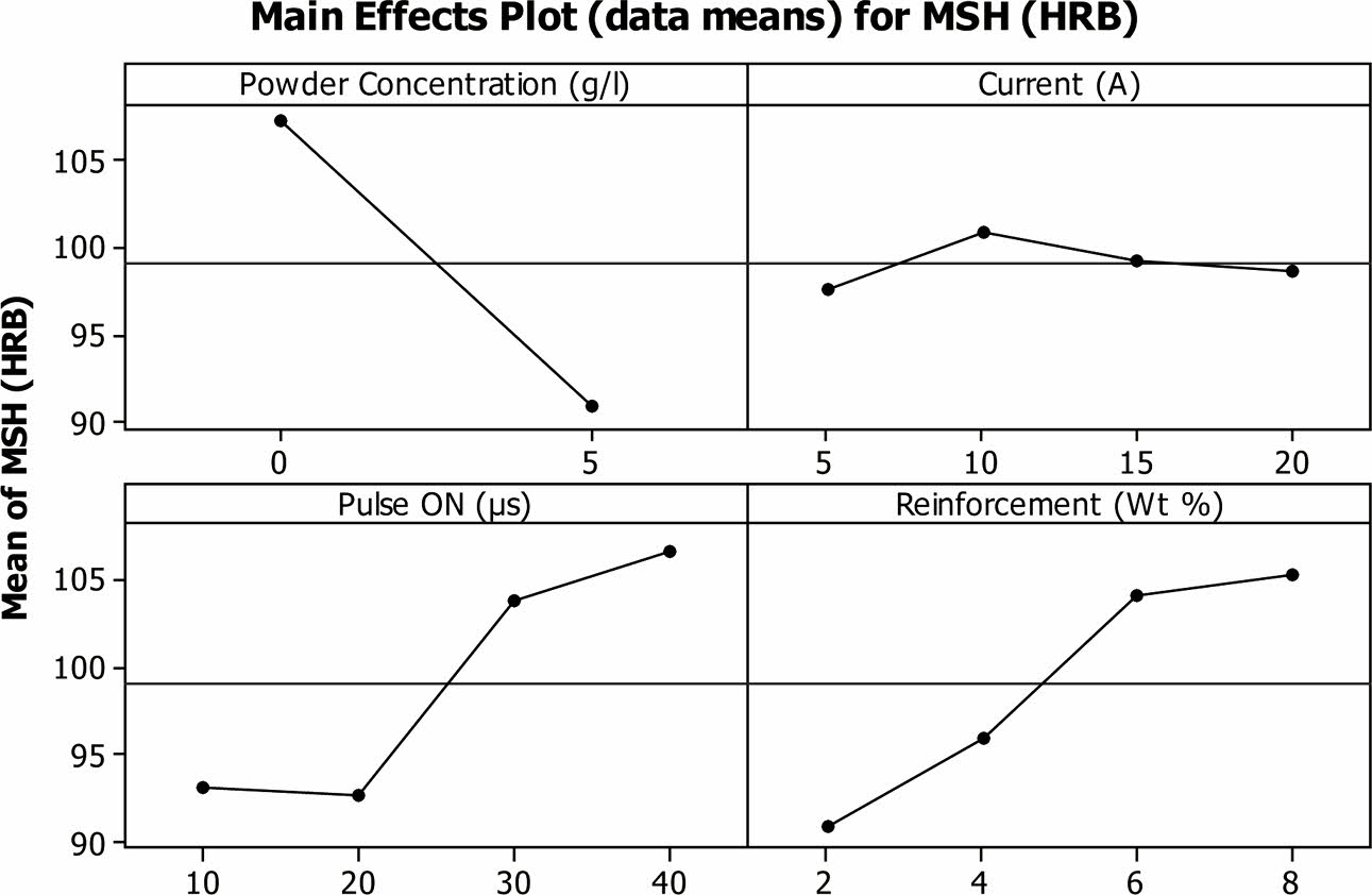
The MSH is affected by several process factors, as seen in Fig. 7. The MSH decreased from 107HRB to 90HRB as a result of adding the powder particles to the dielectric substance. It was shown that the MSH increased when the particles were introduced. decreased as a result of improved machined debris flushing brought on by a rise in spark gap. EDM uses melting and vaporisation to do machining; as a result, molten material is suitably flushed away and MSH rises. As seen by the graph’s flat line, the current has a negligible effect on the MSH of hybrid composites. In the case of Ton, the lowest MSH achieved after 20 µs seconds, machining increases significantly. The material melted and was redeposited on the machined surface as a result of greater Ton produced heat hanging over for a longer amount of time, increasing MSH.
Surface Topography
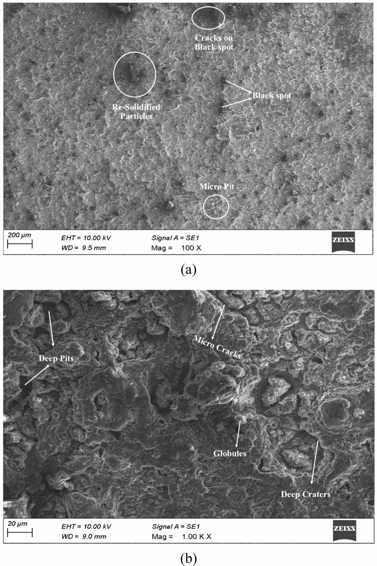
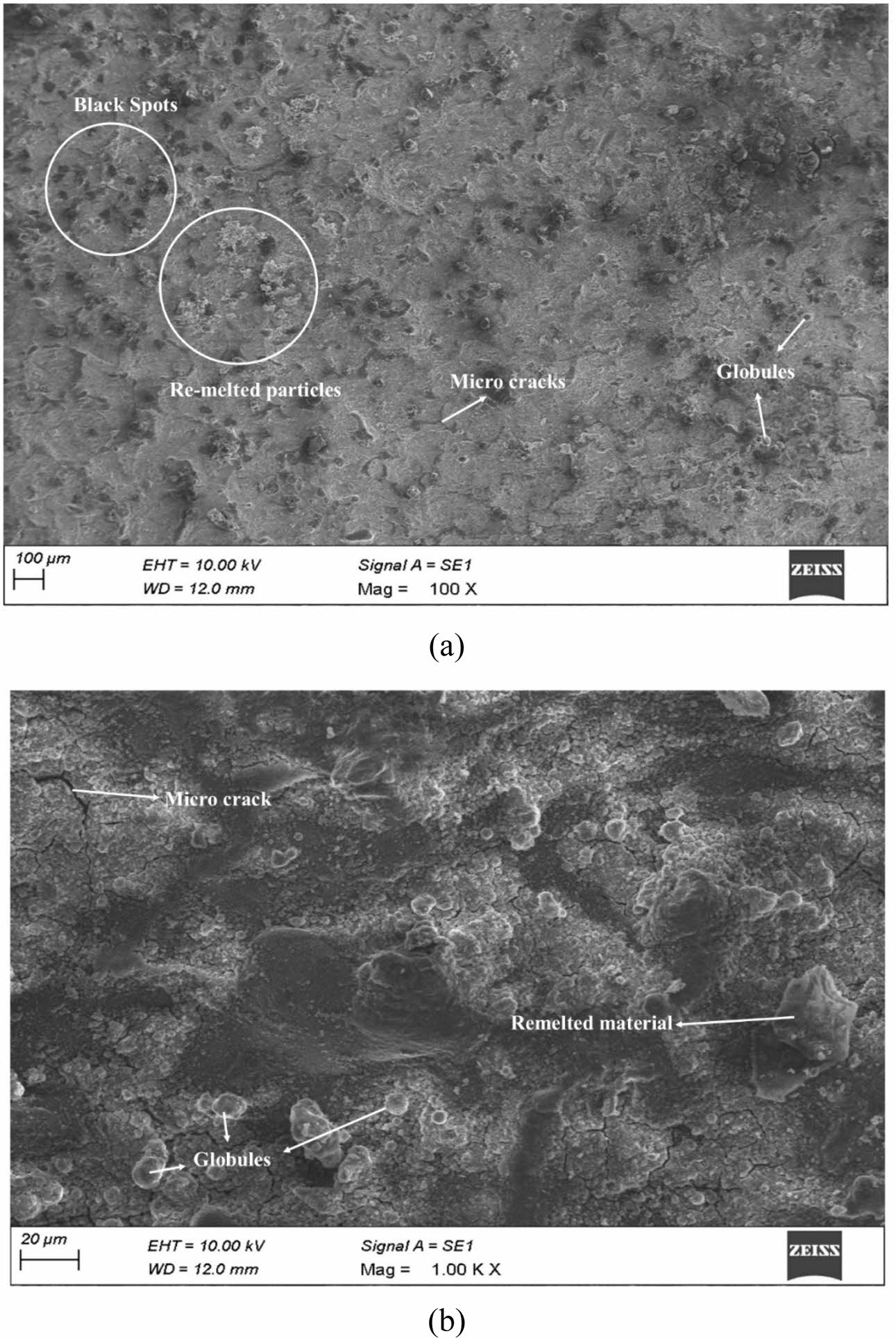
The hybrid AA7050/2Al2O3/2SiC composites’ surface pattern is seen in Fig. 8(a) after the Gr particles were added to the dielectric medium during the machining process. Numerous dark patches and tiny fractures were visible on the surface. The image displayed a crack surrounded by the black spots and resolidified materials. The resolidified materials was the evidence for the insufficient flushing of particles. As seen in Fig. 8(b), the texture was visible at a greater magnification of 1000x and revealed globules, deeper craters, microcracks, and deeper pits. There are obvious small crater troughs along the fracture, which is between 20 and 35 meters long.
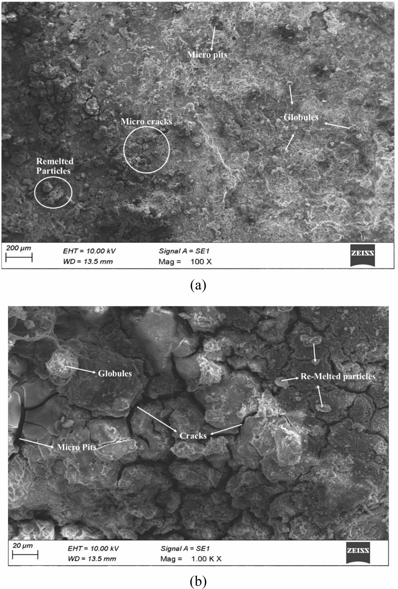
The surface quality of the composites was significantly diminished when the proportion of the strengthening particles was raised to 6 wt%. The morphology was as shown in Fig. 9(a), which included small pits, globules, and an uneven machined surface. The micro cracks were clearly visible which was formed owing to the generation of uncontrollable spark in the machined gap. The texture also showed large numbers of remelted materials occurred because of inadequate flushing. At higher magnification lot of huge cracks observed on the surface because of the uncontrolled bombardment by the sparks. The globule of size 20 µm was observed and lot of materials were redeposited over the surface as shown in the Fig. 9(b). The image also displayed very deeper pits because of these characteristics AA7050/6Al2O3/6SiC exhibits very high Ra value.
The surface texture had several black patches with an additional 8% weight increase in reinforcing particles. Fig. 10(a) shows that the microcracks and globules are clearly discernible. Due to the remelted material being deposited over the machined surface, the surface also shows a significant amount of remelted particles. In compared to a 6 wt% machined surface, fewer fractures are seen at higher magnifications, indicating better surface quality. Fig. 10(b) illustrates how the remelted materials are mostly seen over the surface, causing an uneven machined surface and a higher Ra value.
|
Fig. 1 Impact of distinct input variables on the MRR of AA7050 hybrid composites. |
|
Fig. 2 Impact of distinct process parameters on MRR of AA7050/Al2O3/SiC hybrid composites under Gr PMEDM dielectric medium. |
|
Fig. 3 Impact of various process parameters on the TWR of AA7050/Al2O3/SiC hybrid composites. |
|
Fig. 4 mpact of distinct process parameters on TWR of AA7050/Al2O3/SiC hybrid composites under Gr PMEDM dielectric medium. |
|
Fig. 5 Impact of various process parameters on the Ra of AA7050/ Al2O3/SiC hybrid composites. |
|
Fig. 6 Impact of distinct process parameters on MRR of AA7050/Al2O3/SiC hybrid composites under Gr PMEDM dielectric medium. |
|
Fig. 7 Impact of various process parameters on the MSH of AA7050/Al2O3/SiC hybrid composites. |
|
Fig. 8 Surface topography of AA7050/2Al2O3/2SiC hybrid composites machined at Gr mixed EDM oil (a) At lower magnification (b) At higher magnification. |
|
Fig. 9 Surface topography of AA7050/6Al2O3/6SiC hybrid composites machined at Gr mixed EDM oil (a) At lower magnification (b) At higher magnification. |
|
Fig. 10 urface topography of AA7050/8Al2O3/8SiC hybrid composites machined at Gr mixed EDM oil (a) At lower magnification (b) At higher magnification. |
The results obtained using the stir casting process and EDM machining are as follows.
Due to the high particle density, amalgamations of Gr powder show higher MRR than unmixed conditions but lower MRR when compared to other powder mixed environments. Due to the non-conductive behaviour of the reinforcing materials, the MRR decreased as the weight % of the composites increased.
The TWR attained under Gr particle incorporated dielectric medium was 3.7% higher and 28% lower than Al2O3 and SiC incorporated dielectric medium respectively.
Composites machined under Gr particles incorporated dielectric medium offers least Ra in comparison with the other two PMEDM. It was confirmed that best surface quality was attained by incorporating particles other than the one which was used for the reinforcement of the matrix material. Utilizing SEM, the surface topography was examined.
- 1. S. Gunasekaran, S. Periyagounder, and M. Subramaniam, J. Ceram. Process. Res. 24[4] (2023) 705-713.
-

- 2. Z. Barani, A. Mohammadzadeh, A. Geremew, C.Y. Huang, D. Coleman, L. Mangolini, and A.A. Balandin, Adv. Funct. Mater. 30[8] (2020) 1904008.
-
- 3. S.S. Abuthakeer, Y.A. Parvez and, and J. Nashreen, ECS J. Solid State Sci. Technol. 11[8] (2022), 083005.
-
- 4. R. Vaghefi, A. Nayebi, and M.R. Hematiyan, Mech. 229[11] (2018) 4375-4392.
-
- 5. A. Ramanathan, P.K. Krishnan, and R. Muraliraja, J. Manuf. Process. 42 (2019) 213-245.
-
- 6. Y. Pazhouhanfar and B. Eghbali, Mater. Sci. Eng. A 710 (2018) 172-180.
-
- 7. A.H. Idrisi and A.H.I. Mourad, J. Alloys Compd. 805 (2019) 502-508.
-
- 8. A. Kareem, J.A. Qudeiri, A. Abdudeen, T. Ahammed, and A. Ziout, Mater 14[1] (2021) 175.
-
- 9. D.T. Bui, P. Tsangaratos, V.T. Nguyen, N. Van Liem, and P. T. Trinh, Catena 188 (2020) 104426.
-
- 10. T. Sivaa and K. Anandavelu, J. Ceram. Process. Res. 24[2] (2023) 406-414.
-
- 11. J. Wang, J. Zhang, P. Feng, and P. Guo, Ceram. Int. 44[2] (2018) 1227-1239.
-
- 12. R. Melentiev and F. Fang, CIRP J. Manuf. Sci. Technol. 22 (2018) 1-20.
-
- 13. P. Hema and R. Ganesan, SN Appl. Sci. 2[4] (2020) 1-16.
-
- 14. M.H. El-Hofy and H. El-Hofy, Int. J. Adv. Manuf. Technol. 101[9] (2019) 2965-2975.
-
- 15. J.E. Abu Qudeiri, A. Saleh, A. Ziout, A.H.I. Mourad, M.H. Abidi, and A. Elkaseer, Mater. 12[6] (2019) 907.
-
- 16. A. Pramanik, M.N. Islam, A.K. Basak, Y. Dong, G. Littlefair, and C. Prakash, Mater. Manuf. Process. 34[10] (2019) 1083-1090.
-
- 17. B. Singaravel, K.C. Shekar, G.G. Reddy, and S.D. Prasad, Ain Shams Eng. J. 11[1] (2020) 143-147.
-
- 18. M.U. Farooq, M. Pervez Mughal, N. Ahmed, N. Ahmad Mufti, A.M. Al-Ahmari, and Y. He, Mater. 13[7] (2020) 1549.
-
- 19. T.R. Ablyaz, E.S. Shlykov, K.R. Muratov, A. Mahajan, G. Singh, S. Devgan, and S.S. Sidhu, Micromachines 11[10] (2020) 926.
-
- 20. S. Srivastava, M. Vishnoi, M.T. Gangadhar, and V. Kukshal, Proc. Inst. Mech. Eng. Part B J. Eng. Manufact (2022) 09544054221111896.
-
- 21. R. Ranjith, M. Prabhakar, P. K. Giridharan, and M. Ramu, Surface Topogr. Metrology Prop. 9[4] (2021) 045052.
-
- 22. V.D. Bui, J.W. Mwangi, and A. Schubert, J. Manuf. Process. 44 (2019) 261-270.
-
- 23. T. Prakash, R. Ranjith, S. Krishna Mohan, and S. Venkatesan, Adv. Mater. Sci. Eng. (2022).
-
- 24. V.D. Bui, J.W. Mwangi, and A. Schubert, J. Manuf. Processes 44 (2019) 261-270.
-
- 25. A.K. Rouniyar and P. Shandilya, Proc. Inst. Mech. Eng. Part B J. Eng. Manufact. 233[12] (2019) 2283-2291.
-
- 26. T. Pravin, M. Subramanian, and R. Ranjith, J. Indian Chem. Soc. 99[10] (2022) 100705.
-
- 27. T. Jadam, S.K. Sahu, S. Datta, and M. Masanta, Sādhanā 45[1] (2020) 1-16.
-
- 28. M.A. Ilani and M. Khoshnevisan, Multiscale Multidiscip. Model. Exp. Des. 3[3] (2020) 173-186.
-
- 29. K.B. Mardi, A.R. Dixit, and A. Mallick, Mater. Today: Proc. 4[8] (2017) 8226-8239.
-
- 30. S. Kumar and A.K. Dhingra, Int. J. Automot. Mech. Eng. 15[2] (2018) 5221-5237.
-
- 31. R. Ranjith, P. Tamilselvam, T. Prakash, and C. Chinnasamy, Mater. Manuf. Process. 34 (2019) 1120-1128.
-
- 32. M. Al-Amin, A.M. Abdul-Rani, M. Danish, H.M. Thompson, A.A.A. Aliyu, S. Hastuty, and T.V.V.L.N. Rao, Precision Engineering 66 (2020) 531-549.
-
- 33. S.S. Rao, T. Bhavani, R.K. Nath, P. Maji, S.K. Ghosh, and J.D. Barma, Surf. Rev. Lett. 28[01] (2021) 2030004.
-
- 34. K. Santarao, C.L.V.R.S.V. Prasad, and S.N. Gurugubelli, J. Manuf. Technol. Res. 8[1/2] (2016).
- 35. A. Babbar, V. Jain, D. Gupta, C. Prakash, and A. Sharma, In Characterization, Testing, Measurement, and Metrology in CRC Press (2020) 109-124.
-
- 36. B.S. Khadar, R.M. Jagannadha, and K.O.L.L.I. Murahari, Strojnícky časopis-Journal of Mechanical Engineering 71[1] (2021) 1-18.
-
- 37. C. Somu, R. Ranjith, P.K. Giridharan, and M. Ramu, Surf. Topogr. Metrology Prop. 9[3] (2021) 035025.
-
- 38. M.R. Shabgard, A. Gholipoor, and H. Baseri, Int. J. Adv. Manuf. Technol. 87[5] (2016) 2081-2097.
-
- 39. G. Kibria, I. Shivakoti, and B. Bhattacharyya, Int. J. Manuf. Mater. Mech. Eng. (IJMMME) 4[1] (2014) 22-41.
-
- 40. R. Vinothkumar, J. Maniraj, and V.S. Thangarasu, J. Ceram. Process. Res. 24[3] (2023) 453-460.
-
- 41. Y.P. Zeng, C.L. Lin, J.C. Hung, and C.F. Yang, Mod. Phys. Lett. B 35[29] (2021) 2141014.
-
- 42. M. Prabhakar, R. Ranjith, and S. Venkatesan, Mater. Res. Express 8[8] (2021) 086505.
-
- 43. R. Chakravorty, S.K. Gauri, and S. Chakraborty, Int. J. Eng. Sci. Technol. 4[2] (2012) 34-45.
-
- 44. S. Gunasekaran, S. Periyagounder, and M. Subramaniam, J. Ceram. Process. Res. 24[4] (2023)705-713.
-
- 45. A. Rashid, A. Perveen, and M.P. Jahan, The Int. J. Adv. Manuf. Technol. 116[9] (2021) 2959-2973.
-
- 46. K.P. Maity and M. Choubey, Surf. Rev. Lett. 26[05] (2019) 1830008.
-
 This Article
-
2024; 25(2): 168-177
Published on Apr 30, 2024
- 10.36410/jcpr.2024.25.2.168
- Received on Aug 25, 2023
- Revised on Nov 15, 2023
- Accepted on Nov 29, 2023
Services
Shared
Correspondence to
- A. Vishnu
-
Assistant Professor, Department of Mechanical Engineering, Nandha Engineering College, Erode – 638052
Tel : +91 9629435181 - E-mail: vishnu181a@gmail.com
Clean-Energy Research Institute(CRI), Hanyang University, 222, Wangsimni-ro, Seongdong-gu, Seoul, 04763, Korea
E-mail: jcpr@hanyang.ac.kr