


- Mechanical characterisation of glass fibre reinforced with aluminium wire mesh under various analysis
A. Manikandana,* and G.B. Bhaskarb
aDepartment of Mechanical Engineering, ARS College of Engineering, Maraimalai Nagar, Chengalpattu – 603002, Tamilnadu
bDepartment of Production Technology, Anna university, MIT campus, Chennai-600 044, TamilnaduThis article is an open access article distributed under the terms of the Creative Commons Attribution Non-Commercial License (http://creativecommons.org/licenses/by-nc/4.0) which permits unrestricted non-commercial use, distribution, and reproduction in any medium, provided the original work is properly cited.
GFRP (Glass Fiber Reinforced Plastic) known for its high strength and cost-effectiveness. Aluminium wire mesh is a lightweight reinforcement material made from aluminium wires woven into a mesh pattern, chosen for its availability, strength, and ability to improve the strength of GFRP structures without adding extra weight. The purpose of this research is to figure out how to make glass fiber metal laminates using aluminium wire mesh and GFRP. Aluminium was chosen for its availability, good balance of strength and cost-effectiveness. Glass fibers were also chosen for their strength and affordability. This study’s aim is to enhance the strength of GFRP structures without adding extra weight. To achieve this, the researchers use Aluminium wire mesh as reinforcement. The purpose of this study is to make better Aluminium wire mesh samples using a common method without making them heavier. The aim is to make GFRP structures stronger without making them heavier, making them better for their intended use by the conventional hand-layup method.
Keywords: Composite materials, Glass fibre reinforced with Aluminium wire mesh, Fibre Metal Laminates, GFRP, Analysis.
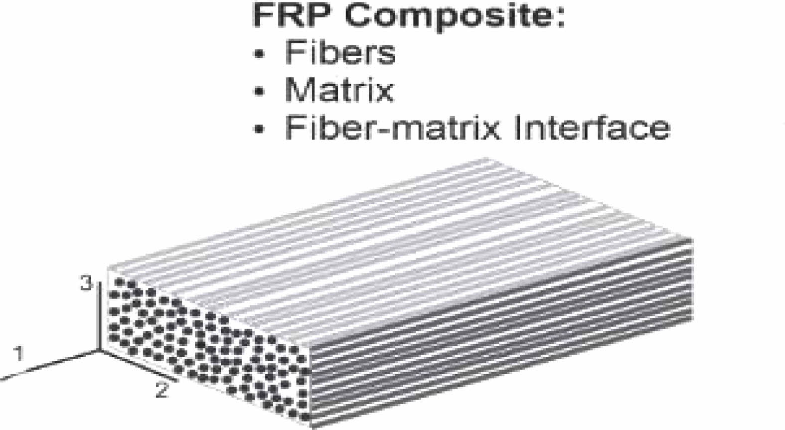
Materials called composites are created by mixing more than 2 different constituents. They are made up of reinforcement, resin, filler, and matrix materials. The physical properties of a base material can be improved by applying mechanical and thermal processes. Composites are used to enhance the base material’s properties. They are created by embedding a reinforcing material, such as fibers, sheets, or particles, into another material, called the matrix.
The combination of more than two materials results in composite materials. An example of this type of material can be found in granite, which is made up of quartz, mica, and feldspar. Historically, composites were used in mud bricks made of clay and reinforced with straw, and mud walls strengthened with bamboo shoots. Today, composites have evolved into things like steel rebars embedded in concrete. The key to making a strong composite material is choosing the right reinforcement to enhance the properties of mechanical of the matrix material.
In the 1950s, the aviation industry sought materials to increase their structural strength and weight capacity.They compared steel and other heavy metals with aluminium alloys and fibre-reinforced composites to see which was more economical. But each had a flaw of its own. Carbon fibre composites had low residual strength, and Aluminium had low impact strength. Using two materials to create a hybrid composite material gained popularity by the late 1970s. The use of numerous thin sheets of material rather than a single thick piece has been found to slow the growth of fatigue cracks, according to researchers at Delft university of technology in the Netherlands. Fibre Metal Laminates (FML) are a novel class of material that resulted from this. Different fibre materials were combined with Aluminium to make these laminates. The first of these materials, ARALL, was introduced in 1978 at the Delft university of technology in the Netherlands. It is made up of alternately thin layers of uniaxial or biaxial aramid fibre preparations and an aluminium alloy (0.2 to 0.4 mm thick).
In the 1990s, once more by Delft University, a significantly superior material was introduced in the aeronautical application by adding glass fibre in alternating layers of the prepreg in a unidirectional format . The most notable difference between them is their specific stiffness, and when compared to aramid fibres, the strength of the glass fibres in the direction of the fibres produced a better strength to volume. So, when compared to aluminium metal alloys and carbon composites from the 1960s, what began as a search for reducing weight in the aviation industry for less fuel consumption resulted in the significant development of GFRP Aluminium fibre metal laminate.In recent years, various methods are gaining prominence in GFRP manufacturing. In this regard, Thirumurugan et al. (2016) [1] used a hand-layup procedure to manufacture a GFRP hybrid with Al laminates & banana fibres using Normal GFRP material. Under ASTM standard tests, the observations found are that the Hybrid composite is superior to the other two composites.
Many authors, Giasin et al. (2015) [2], used Drilling operations to reinforce Aluminium laminate on a GFRP matrix. The tests were conducted in 6mm Solid Carbide TiAlN-coated drills. The observation from this experiment was that the Ply orientation does not affect the cutting force and surface roughness. Feed rate and spindle speed have an impact on cutting force and hole quality. In Huang et al. (2017) [3], a Vertical twin-roll casting was used to make a SS 304 Wire-mesh composite using Al 1060. The resulting structure was tested in Mechanical properties – Tensile and 3-Point bending test. The observations were that improved tensile strength and elongation rate by a change in orientation angle. Through Ismail et al. (2015) [4], Strengthened Beams were observed under epoxy of wire-mesh composite with CFRP sheet. The ASTM standard tensile and load tests revealed that the specimens strengthened with wire-mesh-epoxy composites have increased stiffness. Scientists like Phaneendra et al. (2020) [5] took an alternate method to test the Mechanical properties of the aircraft fuselage using Aluminium(Al) and Stainless Steel(SS) wire mesh with GFRP. The ASTM tests with ANSYS workbench were used, and the results were such that the fabricated composite operations to a entire limitation of the loads conditions with significant impact strength.
Researchers, Rajadurai et al. (2016) [6] used the Hand-layup process on SS 304 wire mesh with sandblasting or electro-dissolution methodology. The composite made had GFRP with 1 N solution of H2SO4 or NaOH. The ASTM standard tests revealed Fine morphological modifications resulting in improved bonding and mechanical properties. Incidentally, Rangaraj et al. (2015) [7] investigated Load testing and Tensile testing operation on Hybrid materials, including Stainless steel wire mesh, aluminium sheet, and perforated aluminium sheet. The matrix material was GFRP, and the tests were ASTM standard tests. The results showed SS wire mesh–reinforced epoxy composite show enhanced flexural strength, and Perforated Aluminium has a better load-bearing capacity. The researchers, Remmers et al. (2001) [8], found that the delamination testing conducted on the fibre metal laminates is partially delaminated under compressive force. This evolved into a numerical model from the experimentation on delamination buckling under the meso-mechanical level. In Sadighi et al. (2012) [9], the research was conducted on Impact testing methodology on fibre metal laminates. The load testing under Aerospace structures was conducted, and the results show superior impact testing ability on various metal laminates. Then Salgar et al. (2016) [10] used Hand-layup and Compression moulding on Varying fibre/epoxy volume fractions from 40% to 60% with GFRP. The ASTM standard tests revealed an increase in fibre content and increased mechanical properties but reduced brittleness and started delamination. Through Sunil Bhat et al. (2014) [11], Sheet metal processing was studied with T6 aerospace aluminium alloy sheets. The Epoxy resin E-glass fibre was used under X-ray spectroscopy tests, through which, the quality of interfaces between un-identical material layers of the laminate is observed.
The mechanical strength behavior of epoxy resin hybrid composites reinforced with silane treated e-glasses fiber, Aluminium 6061, and stain-less steels 304 metal wire-mesh (2018) [12]. The study focuses on the significance of silane treatments on the metal surfaces to enhance resistance of the adhesion and delamination in the composite. The use of hybrid fibers-reinforced polymer composites discusses the benefits of hybridization, combining different fibers and filler particles, to enhance mechanical properties (2020) [13] such as specific strength, low weight, and corrosion resistance. This influence of mullite (M) and aluminium titanate (AT) additions investigates on the physical and mechanical properties of yttria-stabilized zirconia (YSZ) ceramic composites. The combination of wet ball milling and dry pressing, followed by sintering at different temperatures and times, reveals enhanced density, reduced porosity, and improved mechanical strength, particularly in YSZ samples with mullite reinforcement sintered at 1600 °C for 5 hours, showcasing potential advancements in ceramic composite materials (2019) [14]. The dry sliding wear characteristics of LM24 aluminum alloy composites reinforced with nano alumina (Al2O3) and graphite (Gr) prepared through stir casting. Through a comprehensive experimental design, the study identifies optimal wear parameters, achieving a minimum wear rate of 0.0021 mm3/m and a minimum coefficient of friction of 0.141 for LM24-Al2O3-Gr hybrid composites (2023) [15]. The method of fabricate organic-inorganic hybrid nanofiber filters by electrospinning LaMnO3 and LaMn0.5Fe0.5O3 nanofibers into polyacrylonitrile (PAN). The resulting filters, exhibiting enhanced oxygen defects in LaMn0.5Fe0.5O3, demonstrate improved performance with filtration efficiency and pressure drop, surpassing a reference H11 nonwoven fabric (2023) [16]. In order to improve sustainability and cost effectiveness, research in the field of concrete technology focuses on the partial substitution of Portland cement with ceramic waste powder. Research has shown that adding ceramic waste powder to 20% of the cement can greatly increase the concrete strength’s while also having positive environmental effects (2024) [17]. Using ceramic fibers to strengthen porous alumina ceramic with the goal of increasing mechanical strength and structural integrity is the field of ceramic engineering. The physical characteristics and compressive strength of the resultant porous ceramic are significantly improved by the addition of ceramic fibers to colloidal suspensions, which creates a wall structure that contains fibers (2023) [18]. For many high-tech sectors, the development of functional ceramic composites is crucial, especially for multilayer ceramic capacitors (MLCCs). By enhancing bending resistance, reducing solder breakdown under thermal shock, and offering superior moisture resistance, the use of Ag-epoxy electrodes in MLCCs improves reliability (2022) [19]. Synthesis of composite materials such as CeO2/Zirconia Toughened Alumina (ZTA) for advanced functional qualities is one of the novel techniques in ceramic material research. Significant gains in hardness, fracture toughness, and coefficient of friction have been made possible by powder metallurgy processes and characterisation techniques like SEM and XRD, which qualify these composites for demanding applications (2023) [20].
Fabrication of FML is carried out in much research, but its bonding and delamination during machining are not taken care of. So, this research mainly gives importance to delamination, machining characteristics and other properties like the strength and toughness of fibre metal laminates.
Methods: The research uses aluminum wire mesh to make the composites. The hand-layup method is used to create a GFRP and aluminum wire mesh hybrid. A regular GFRP sample is used as a comparison for the mechanical testing. The created materials are cut to meet a standard and then evaluated for their mechanical strength through various tests such as low velocity impact, flexural, tensile and dynamic mechanical analysis.
Findings: Testing revealed that the composite made of GFRP and aluminium wire mesh performed well under heavy loads and had superior properties to the regular GFRP sample used as a comparison.
Improvement/Applications: GFRP’s mechanical properties are shown to be significantly improved by the addition of aluminium wire mesh, leading to better impact resistance, flexibility, tensile strength, and dynamic behaviour, according to the results.
Materials
Glass fibres used in the research are 300 gsm and are locally sourced. It was cut into 32 cm length and 15.5cm breadth to make them into layers using resin. The resinconsists of two entities which are (1) a medium viscosity epoxy resin called ARALDITE LY556 and (2) a hardener called ARALDITE HY951. Both these materials are mixed at a ratio of 90% resin and 10% hardener. The matrix material is prepared with much care, accounting for the importance that the resins are the binding agents for the fibre reinforcement, which is ultimately towards the high strength of the composite and assists the fibres in carrying the loads. Mould is made using source material of mild steel plate of 40 cm in length, 20 cm in breadth and Thickness of 12 mm. This source material is machined using CNC to 36 cm length, 15 cm breadth, and 10 mm Thickness. A cavity of 4.5 mm is made in the lower plate, and 12 screw threads are slotted to join the two plates. For joining the two plates,the Allen screw is used and tightened by the Allen key.
A release film is coated in the form of Wax on both the mould top and bottoms before applying the resin. An Aluminium wire mesh of Thickness 0.5 mm is locally sourced
Methods
Hand-layup technique is used for the composite fabrication process. The required infrastructure for this method is minimal, and the process is summed up using the simple steps. The surface of the moulds is initially coated with an adhesive gel to prevent the polymer from adhering to it. To achieve a high-quality finish on the surface of the products, thin sheets of plastic are employed at the mould top and bottom plates.
The Perspex sheet is laid over the reinforcements, which are made of woven mats or chopped strands mats, according to the size of the moulds. The liquid thermo-setting polymers are then completely combined with the recommended hardener (curing agent) in the right proportions and poured onto the surface of the mats that have previously been put in the mould. A brush is used to distribute the polymer evenly. Following the placement of the second layers of the mats on the surface of the polymer, the surplus polymers and any trapped air are removed by lightly rolling the mats-polymer layers with the rollers. Mould before and during the application of resin taken.
Up until the necessary number of layers have been added, the procedure continues for each of the layers of polymers and mats. The top mould plates are held on the stack of layers once the sheet of plastic has been placed, releasing gel has been sprayed on its inner surfaces, and force has then been released. The created composites item is removed from the mould once curing, and stored at the temperature of the room or at the appropriate temperatures. The kind of polymers employed in manufacturing composites will determine how long the composites must cure. The typical room temperatures cure time for an epoxy-based mechanism is between 24 and 48 hours. The principal applications of this technique are thermo-setting polymer-based composites. The various fabrication processes are conducted.
Two hundred grams of fibre and 200 grams of resin and hardener mixture (prepared in a 90-10 ratio) are taken to prepare the test sample. At the bottom of the Aluminium wire mesh,five layers are stacked, and above the Aluminium wire mesh,five layers are stacked. After the application of resin, it is provided to cure at the temperatures of 140 °C for 3 hrs and cut to test specification.
Low Velocity Impact Test
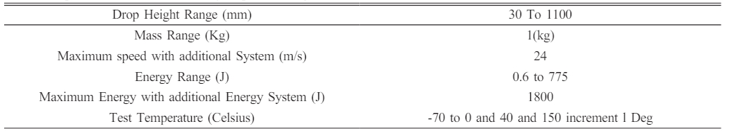
The impact testing setup used in the Aerospace department at MIT campus, Chennai, for conducting low-velocity impact tests. The machine, consisting of an instrumented falling weight testing setup with a 2 kg impactor, allows researchers to control and limit the maximum impact energy using adjustable falling height, facilitating the investigation of material behavior and structural response under impact conditions.
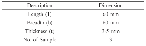
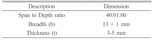
The volume of the impactors and the extent of the drop combined define the impact’s energies. As mass and height grow, the dart’s potential for energy rises. When the tool-holding component is released, the possible power is transformed into its kinetic energy. The machine specifications are tabulated in Table 1, and the sample dimensions, according to ASTM D 5628, are tabulated in Table 2.
Procedure: Following ASTM D 5628, a batch of the square specimen is clamped on the fixtures with the rectangulars-slot. The conditions for the impact tests are as follows:
A hemispherical head with a 10 mm radius adorns this dart.
•Impact velocity = 3 m/s, 4 m/s, 5 m/s
•Applied mass = 0 kg
•Total mass = 1.926 kg
•Support diameter = 60 mm
•Clamping force = 100 N
The standardized cylindrical rods that make up the darts has the piezoelectric load cells attached to the other end, where the pushing weight is linked. To reduce friction that would have been created while the impactor’s drop, the vertical supports of the impact’s towers were routinely greased.
Flexural Test
It helps to determine the flexural properties of glass fibre-Aluminium composites. The test is done by the 3-point loading systems employed to the simplier supported beams. Specimens for the flexural test were cut following ASTM D 7264 standards. Then they were tested for flexural strength using the universal testing machine UTM by use of the software Instron-3367 by applying flexural load.
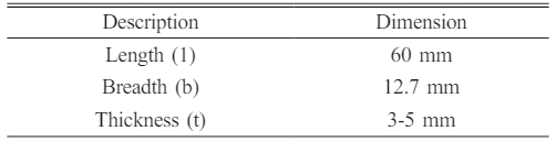
The 3-point bending testing is conducted on rectangular specimens. The specimens measure 10 centimeters in length, 10 millimeters in width, and 10 millimeters in height (b, h). The actuator provides the pressure precisely in the center of 2 supports (L/2) while specimens are supported by 2 supports that are spaced away by 5 cm (L). The Instron measures the forces (F) of 50N and a 2mm distortion just prior to failures. We must ascertain the specimen’s Young’s Modulus (E) and maximal flexural strength (s). The specimen dimensions, according to ASTM D 7264, are shown in Table 3.
Procedure for Flexural Test
1. A rectangular bar cross section rests-on 2 supports and is loaded utilizing the loading noses mid-ways among the supports.
2. The support spans-to-depth ratios of 40:1 is utilized.
3. The specifications used are:
•Total length – 80 mm
•Span Length – 60 mm
•Breadth – 13 mm
•Thickness – 4.32
4. The loads are employed with the cross-head speeds of 1 mm/min, whereas the maximum load of 5 kN can be applied.
5. The specimens are deflected until ruptures appearence in the outer surfaces of the testing specimens or until the optimum strains are achieved.
Tensile Test
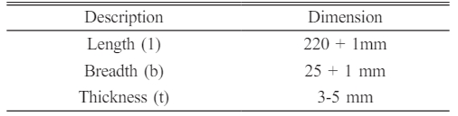
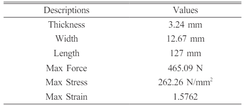
A specimen is put through controlled stress unless it fails in an essential test for the science of materials called tensile test. Choosing the materials for use typically involves using the test findings. The tensile characteristics of glass fiber and aluminium composites may be determined. Specimens for the tensile test were cut following ASTM D3039 standards, and then they were tested for flexural strength using the universal testing machine applying flexural load. The dimensions were tabulated in Table 4.
Procedure for TensileTest
1. Two bar rectangular cross-section supports the specimen at both theends
2. Specimenspecifications
a. Total length – 220 mm
b. Span length – 120 mm
c. Supporting length – 50 mm on each side
d. Breadth – 25 mm
e. Thickness – 3.24 mm
f. Crosshead speed –1 mm/min
4. The tensile test is carried out by which the tensile loads are employed to the specimens.
5. The specimen breaks when the optimum tensile loads are achieved, and thus the tensile strength was found.
Dynamic Mechanical Analysis Test
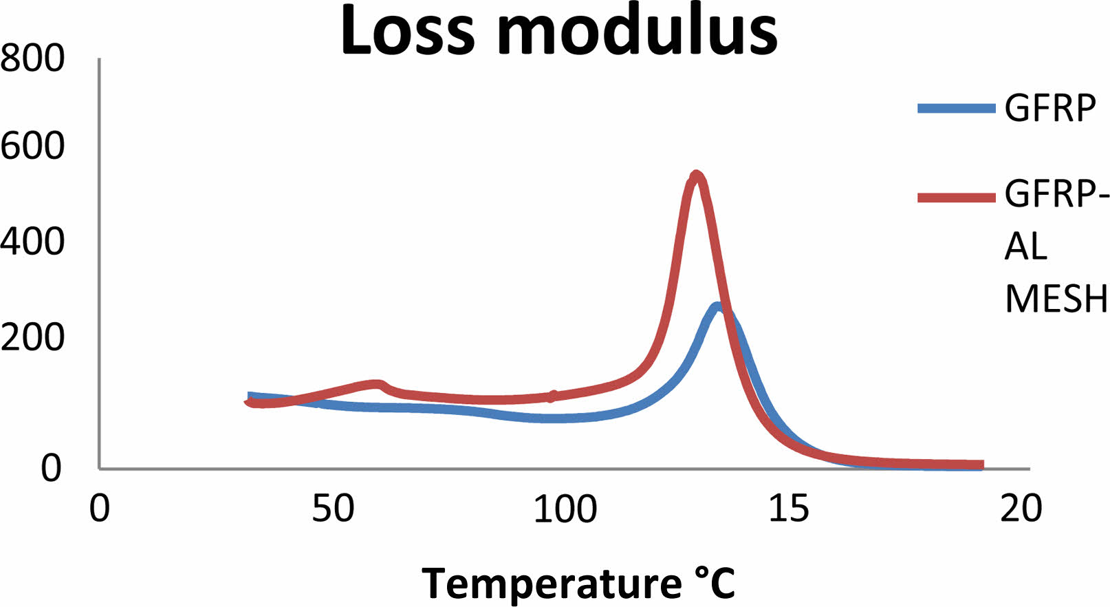
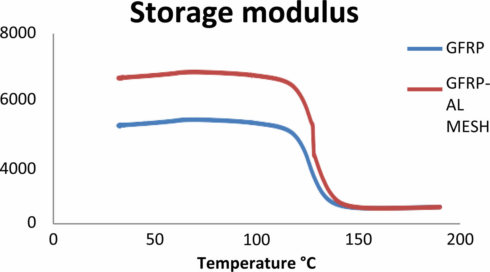
For establishing the morphology and viscoelastic characteristics of crystalline polymers and material composites in connection with initial adaptations and other significant variables, including cross-linking density, dynamic vulnerability dynamic/complex viscosity storage/loss regulation, creep compliance/stress-relaxation modulus, and the non-Arrhenius variations of relationship times with temperatures, dynamic analysis of mechanical properties is an essential and helpful tool. Young’s modulus is frequently connected to the memory modulus (E’) or dynamic modulus. It frequently refers to a material’s “stiffness” and establishes the degree to which rigid or fragile the specimen is. E’ is viewed as a material’s propensity or capacity to preserve Energy employed to prepare it for use in future periods. Loss modulus (E), also known as dynamic losses modulus, is a viscous reaction material’s properties and is thought to be a measure of how easily energy evaporates by it.
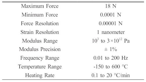
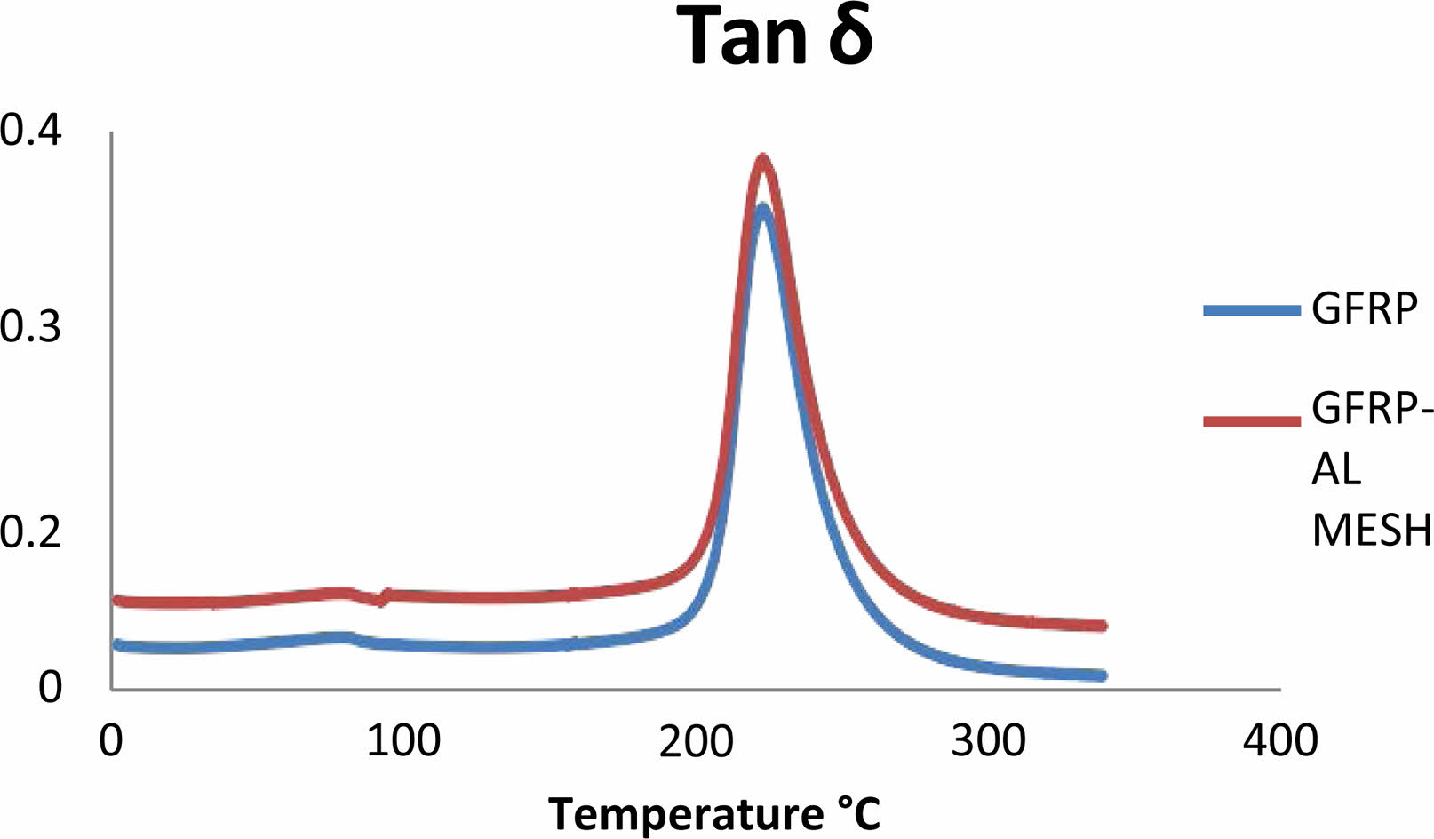
The dynamic losses modulus are frequently associated with “internal frictions” and is sensitive to many types of molecular’s motions, transitions, processes of relaxations, morphologies and other structural heterogeneities. Tan δ is expressed as a dimensionless number and regarded as the mechanical damping factors depicted as the ratios of losses and modulus of the storage (Tan δ = E”/E’). The DMA test was conducted in CIPET, and the image of the machine is shown in Fig. 10. The samples were cut depending on ASTM D 4065, and the values are tabulated in Table 5. The machine specifications are listed in Table 6.
For ease of comparison, the material composites fabricated are termed GFRP -AL MESH and the base GFRP (controlsample). This helps us to form a baseline comparison with and without an aluminium laminate in a GFRP sample testing procedure. Fig. 1 Fig. 2 Fig. 3 Fig. 4 Fig. 5 Fig. 6 Fig. 7 Fig. 8 Fig. 9
|
Fig. 1 Fibre-reinforced composite. |
|
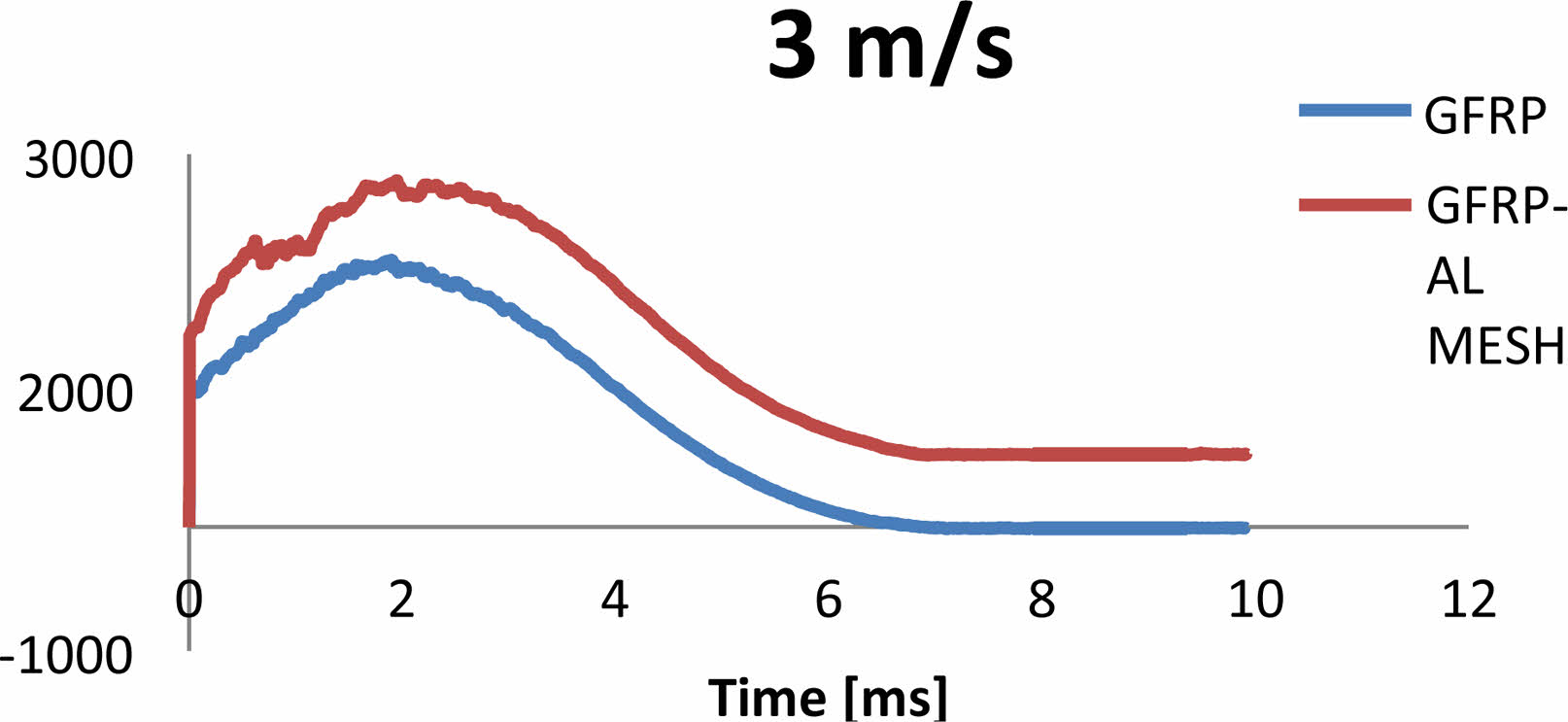
Fig. 2 Impact resistance Vs Time graph for GFRP-AL MESH and GFRPLaminate at 3 m/s. |
|
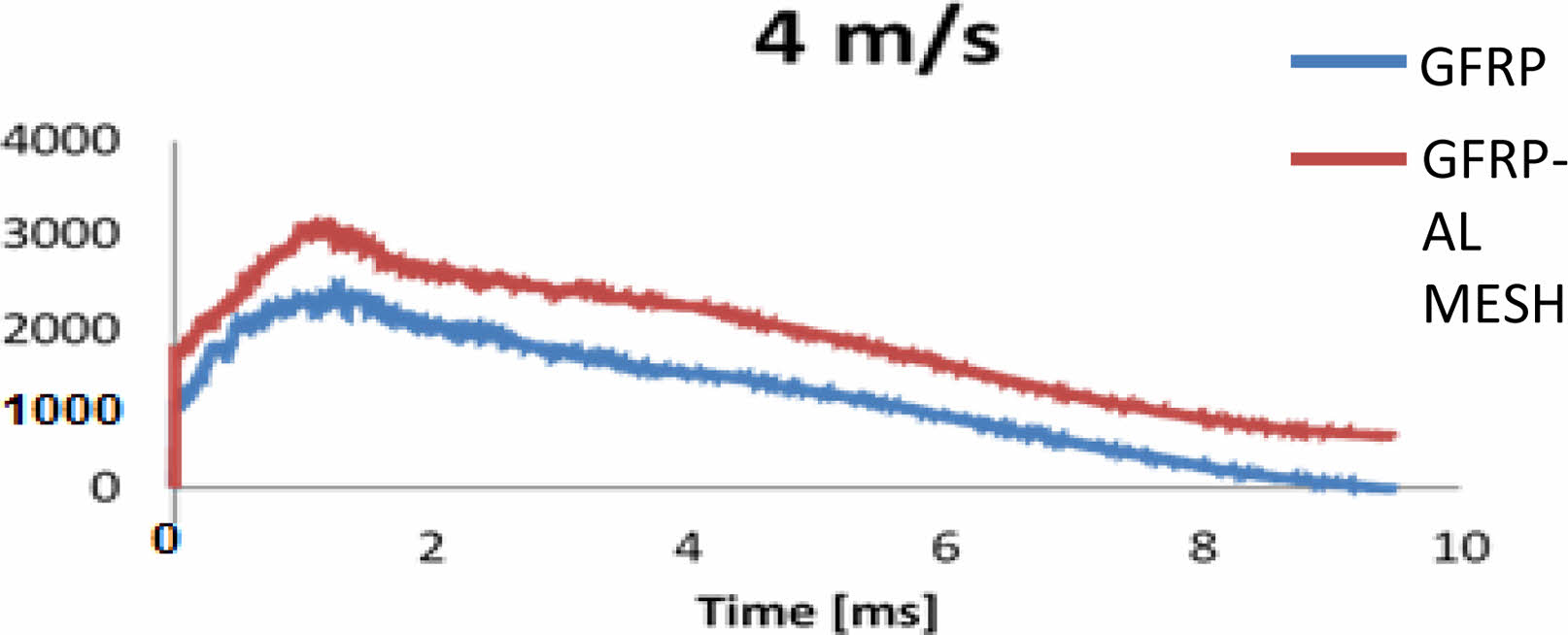
Fig. 3 Impact resistance Vs Time graph for GFRP-AL MESH and GFRPLaminate at 4 m/s. |
|
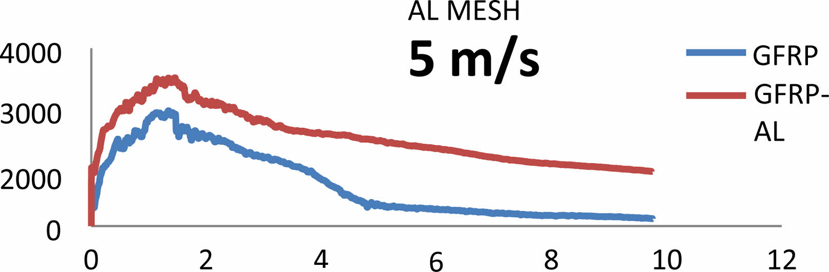
Fig. 4 Impact resistance Vs Time graph for GFRP-AL MESH and GFRPLaminate at 5 m/s. |
|
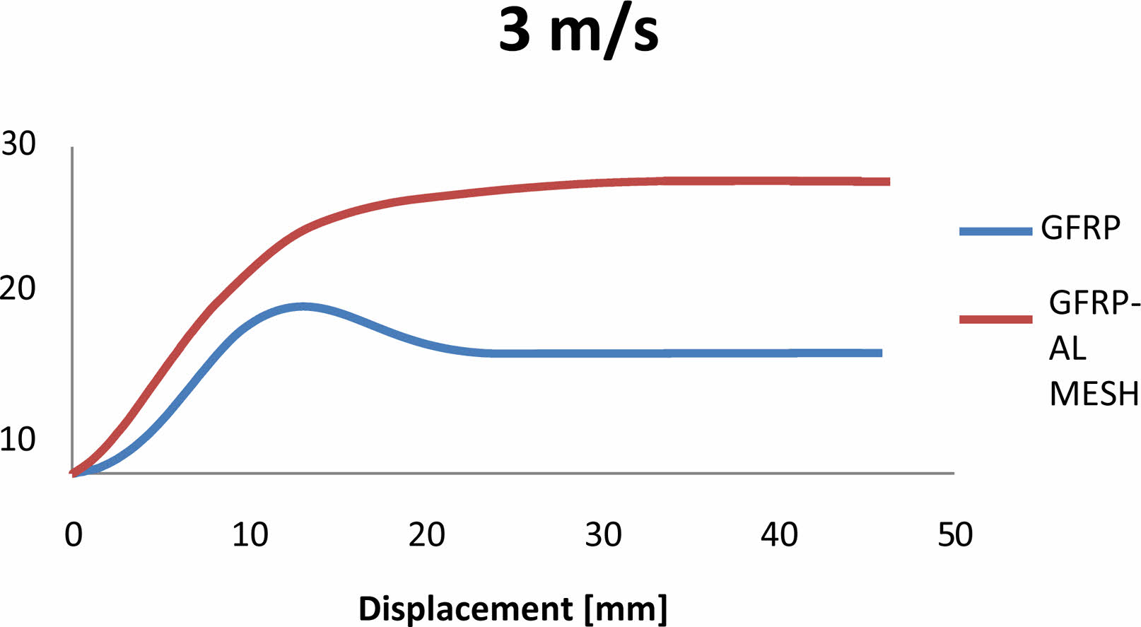
Fig. 5 Absorbed energy Vs displacement graph for GFRP-AL MESH and GFRP Laminate at 3 m/s. |
|
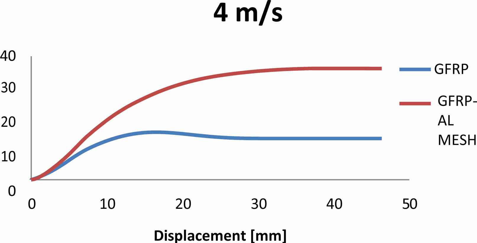
Fig. 6 Absorbed energy Vs displacement graph for GFRP-AL MESH and GFRP Laminate at 4 m/s. |
|
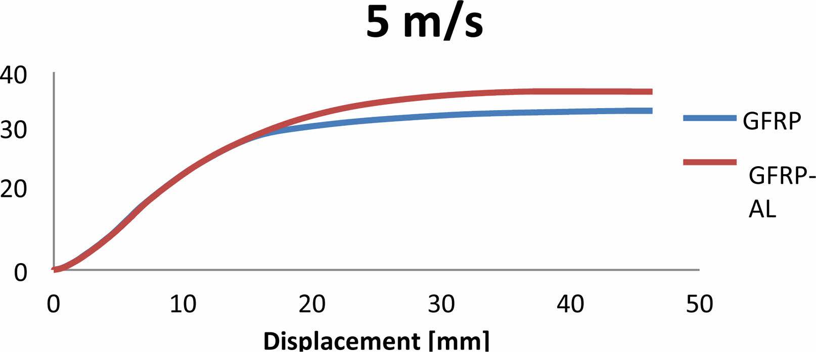
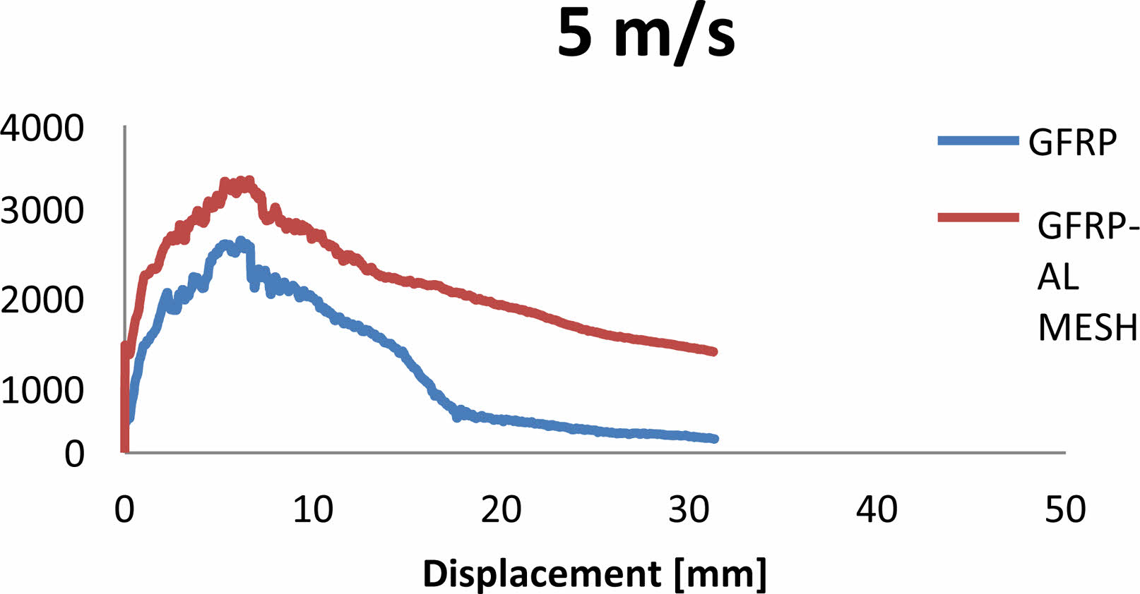
Fig. 7 Absorbed energy Vs displacement graph for GFRP-AL MESH and GFRP Laminate at 5 m/s. |
|
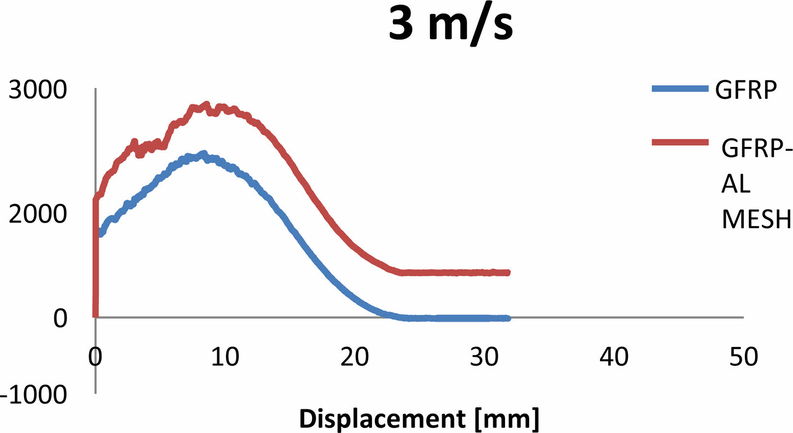
Fig. 8 Impact resistance Vs Displacement graph for GFRP-AL MESH and GFRP Laminate at 3 m/s. |
|
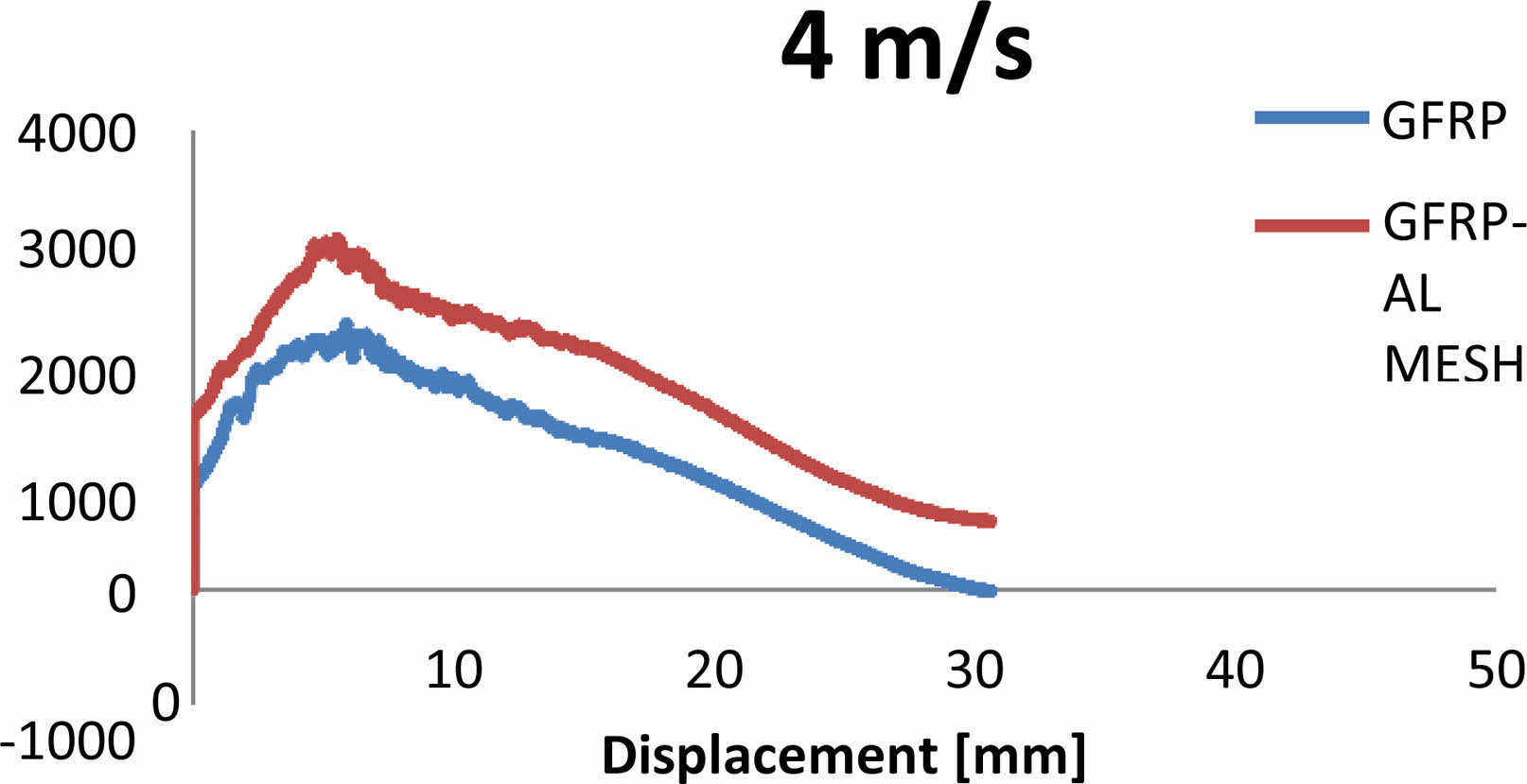
Fig. 9 Impact resistance Vs Displacement graph for GFRP-AL MESH and GFRP Laminate at 4 m/s. |
|
Fig. 10 Impact resistance Vs Displacement graph for GFRP-AL MESH and GFRP Laminate at 5 m/s. |
Low Velocity Impact Test
The impact tests on the composite specimens were performed at speeds of 3 m/s, 4 m/s, and 5 m/s and the thickness of the laminate was 3.24 mm. The positions and accelerations of the impactors were recorded throughout the test. The power absorbed during the impacts were computed depending on the height and acceleration readings and the results were plotted on graphs. Figs. 2 to 4 show the impact resistance over time for each velocity. Figs. 5 to 7 show the relationship between absorbed energy and displacement. Figs. 8 to 10 show the relationship between impact resistance and displacement The peak values are presented in Tables 7, 8 and 9.
The Table 7, 8 and 9 presents the results of maximum energy absorbed (in joules) and the maximum force applied (in newtons) for two different materials: GFRP-AL MESH (Glass Fiber Metal Laminate with Aluminium Wire Mesh reinforcement) and Glass (presumably referring to GFRP without the aluminium mesh). It indicates that GFRP-AL MESH exhibits higher energy absorption and force resistance compared to conventional Glass GFRP, making it a stronger and more robust material for applications requiring impact resistance.
Flexural Test
For the glass fibre aluminium composites, the yield load is 0.4650 kN. From that yield load, flexural strength for our laminates has been discussed. The flexural strength of GFRP-AL MESH laminate is 664.5 MPa. For the general GFRP composites, the yield load is 0.2855 kN. From that yield load, The flexural strength of GFRP laminate is 106.9 MPa (Table 10 and Table 11).
Flexural strength = 3 × Force × Length / (2 × Breadth × Depth2)
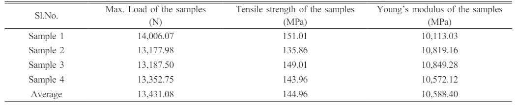
Tensile Test
Tensile strength for GFRP-AL MESH = peak load/ (original width × originalthickness)
Tensile strength for GFRP = peakload/(width × thickness)
Dynamic Mechanical Analysis Test
The DMA test was conducted, and the result of GFRP-AL MESH and GFRP was obtained; based on the result, the graph is plotted between temperature and loss modulus and the graph between temperature and storage modulus and the graph between temperature and tan delta and these graphs were compared and shown in Figs. 11 to 13. Fig. 12
The challenges in making glass fiber metal laminates using aluminium wire mesh and GFRP include achieving a proper bond between the materials to ensure effective load transfer and addressing potential issues related to differential thermal expansion between the different components.
|
Fig. 11 Graph plotted between Storage modulus and Temperature |
|
Fig. 12 Graph plotted between Loss modulus and Temperature. |
|
Fig. 13 Graph plotted between Tan delta and Temperature. |


The results of this study suggest that adding aluminum wire mesh to composite laminates leads to increased bonding strength and improved impact resistance, as seen through low-velocity impact and flexural tests. Samples with aluminum wire mesh showed higher impact resistance compared to regular glass-fibers reinforced polymers-composites.
Both glass fiber aluminum wires-mesh reinforced composite laminates (Fabricated) and glass fiber reinforced polymer composites laminates (Control) were made utilizing the hand lay-up technique and were subjected to various mechanical tests. The results showed that incorporating aluminum wire mesh improved properties of mechanical such as tensile strength, impact resistance, and strengths of flexural.
Dynamic mechanical evaluations were additionally executed to estimate the damping characteristics of the two types of laminates at different frequencies. The glass-fibers aluminum wires-mesh reinforced composite laminates exhibited better damping characteristics due to improved adhesion between the matrix and reinforcement. Adding aluminum wire mesh to GFRP had significant effects on its mechanical properties, resulting in improved impact resistance, flexibility, tensile strength, and dynamic mechanical properties.
No participation of humans takes place in this implementation process
No violation of Human and Animal Rights is involved.
No funding is involved in this work.
Data sharing not applicable to this article as no datasets were generated or analyzed during the current study
Conflict of Interest is not applicable in this work.
All authors are contributed equally to this work
There is no acknowledgement involved in this work.
- 1. A. Thirumurugan, G.B. Bhaskar, K. Poyyathappan, R. Jai Karthik, M. Kishore Kumar, G. Somasundaram, and G. Venkatakrishnan, Indian J. Sci. Technol. 9[42] (2016) 1-7.
-

- 2. K. Giasin, S. Ayvar-Soberanis, and A. Hodzic, Compos. Struct. 133 (2015) 794-808.
-
- 3. H. Huang, J. Wang, and W. Liu, Adv. Mech. Eng. 9 (2017) 1687814017716639.
-
- 4. I.M. Qeshta, P. Shafigh, and M.Z. Jumaat, Constr. Build. Mater. 79 (2015) 104-114.
-
- 5. A.N. Phaneendra, G. Sankaraiah, V. Diwakar Reddy, and R. Meenakshi Reddy, Adv. Mater. Process. Technol. 7 (2021) 288-303.
-
- 6. A. Rajadurai and N. Karunakaran, J. Mech. Sci. Technol. 30 (2016) 2475-2482.
-
- 7. R. Ranga Raj, R. Velmurugan, C. Dinesh, and S. Balaji, J. Eng. Res. App. 5 (2015) 80-88.
- 8. J.J.C. Remmers and R. De Borst, Compos. Sci. Technol. 61 (2001) 2207-2213.
-
- 9. M. Sadighi, R.C. Alderliesten, and R. Benedictus, Int. J. Impact Eng. 49 (2012) 77-90.
-
- 10. A. Swapnil Salgar, B. SatheSandip, P. ChaudhariBapu, and S. Jagadale Vishal, Mater. Today: Proc. 4 (2017) 9487-9490.
-
- 11. S. Bhat and S. Narayanan, J. Eng. App. Sci. 9 (2014) 1606-1614.
-
- 12. V.R. Arun Prakash, and S. Julyes Jaisingh, Silicon. 10 (2018) 2279-2286.
-
- 13. G.R. Chavhan and L.N. Wankhade, Mater. Today: Proc. 27 (2020) 72-82.
-
- 14. Israfil Kucuk and Tahsin Boyraz, J. Ceram. Process. Res. 20[1] (2019) 73-79.
-
- 15. R. Surendran and A. Kumaravel, J. Ceram. Process. Res. 24[5] (2023) 899-906.
-
- 16. H.S. Kim, H.-J. Kim, Y. Kim, and J.-W. Yoon, J. Ceram. Process. Res. 24[5] (2023) 827-834.
-
- 17. S. Anandaraj, A.R. Krishnaraja, P. Kulanthaivel, and P.C. Murugan, J. Ceram. Process. Res. 25[1] (2024) 41-47
-
- 18. K.N Fatema, H.M. Lim, J.S. Hong, K.S. Lee, and I.J. Kim, J. Ceram. Process. Res. 24[1] (2023) 197-204.
-
- 19. C.H. Lee and J.R. Yoon, J. Ceram. Process. Res. 23[2] (2022) 181-187.
-
- 20. P. Ganeshan, Y. Sravani, K. Raja, and B.K. Singh, J. Ceram. Process. Res. 24[5] (2023) 781-787.
-
 This Article
-
2024; 25(2): 159-167
Published on Apr 30, 2024
- 10.36410/jcpr.2024.25.2.159
- Received on Oct 18, 2023
- Revised on Nov 30, 2023
- Accepted on Dec 5, 2023
Services
- Abstract
introduction
materials and methods
results and discussion
conclusion
- Ethics Approval and Consent to Participate
- Human and Animal Rights
- Funding
- Data availability statement
- Conflict of Interest
- Author Contributions
- Acknowledgements
- References
- Full Text PDF
Shared
Correspondence to
- A. Manikandan
-
Department of Mechanical Engineering, ARS College of Engineering, Maraimalai Nagar, Chengalpattu – 603002, Tamilnadu
Tel : +91 9600123587 - E-mail: manimagnuss@gmail.com
Clean-Energy Research Institute(CRI), Hanyang University, 222, Wangsimni-ro, Seongdong-gu, Seoul, 04763, Korea
E-mail: jcpr@hanyang.ac.kr