- Analysis of friction stir welding of AZ91D magnesium alloy with boron application using TOPSIS Taguchi method
K. Rajesh Kumara,*, Kiran Kumar Damab and Vaddi Venkata Satyanarayanac
aResearch Scholar, Department of Mechanical Engineering, Koneru Lakshmaiah Education Foundation, Vaddeshwaram, Andhra Pradesh, India
bAssociate Professor, Department of Mechanical Engineering, Koneru Lakshmaiah Education Foundation, Vaddeshwaram, Andhra Pradesh, India
cProfessor, Department of Mechanical Engineering, Vidya Jyothi Institute of Technology, Hyderabad, IndiaThis article is an open access article distributed under the terms of the Creative Commons Attribution Non-Commercial License (http://creativecommons.org/licenses/by-nc/4.0) which permits unrestricted non-commercial use, distribution, and reproduction in any medium, provided the original work is properly cited.
Friction stir welding of AZ 91D magnesium alloy has been undertaken with boron powder application at the interface. Multi responses are measured with different characteristics. The responses are analyzed with variable weightages employing TOPSIS Taguchi method. Optimal parameter condition has been identified and found that weld speed is playing major role in controlling all the responses. The performance is computed for the optimum case and also the ANOM and ANOVA test is conducted to show the performance improvement
Keywords: FSW, Magnesium alloy AZ91D, TOPSIS taguchi method, OA ANOM, ANOVA
Magnesium alloys are light in weight and are used as structural members in aerospace and automotive industries. The advantages of magnesium and its alloys are lowest density, high specific strength,good castability, improved corrosion resistance etc. While the disadvantages of it includes low elastic modulus, low cold workability and toughness. SiC nanoparticles reinforced Mg-based MMCs have been fabricated in attempt to obtain light weight materials with better mechanical properties. Magnesium alloys are easily oxidized in weld zone because of theirhigh chemical reactivity even at moderate temperatures. At high temperature in the range 200-500 oC the magnesium AZ91D alloy exhibits changes in microstructure and partial dissolution of minority phases. Failure occurs basically by inter crystalline splitting along the boundaries of original dendrites. With the chage in shape of tool profilethe material flow behavior is influenced and the mechanical properties are effected with formation of grains in joints of FSW components. The joining of these alloys with other engineering materials specially with aluminum alloys will further lead to more weight saving in the finished components [1, 2]. The magnesium alloys are susceptible to hot cracking and oxide formation during fusion welding Process [3, 4]. Friction stir welding (FSW) is a prospective method employed to join the magnesium alloys eliminating the formation of weld defects [5]. The tool steels are used as the materials for rotary tools in FSW effectively owing to their high temperature strength [6]. Due to dynamic recrystallization the grain size is reduced to a size of 1-20 µm in the friction stir welding of magnesium alloys [7]; With special cooling the grain size was reduced to 25-100 nm [8, 9]. The yield strength of magnesiumjoints, increased with increase in tool transverse speed, but the deformation is non uniform due to microstructural differences that exists across these zones [10]. With the reinforcement of SiC nanoparticles in the FSW of AZ 31 with AA7075 the weld microstructure was affected by pinning mechanism [11]. A decrease in average grain size with reduction in tool rotation rate along with the increase of tool transverse velocity is observed [12]. In AM50 Mg alloy the grain reduction from 500 to 100 µm is observed with the addition of boron from 0 to 0.15% [13]. In this investigation the effect of boron addition on microstructure and mechanical properties of AZ 91D magnesium alloy is undertaken employing FSW process.
Materials
AZ 91D Magnesium alloys are employed in the present study in the form of plates of 5 mm thick and the chemical composition, mechanical and thermalproperties are illustrated in Table 1 and 2 respectively. The edge of a plate is provided with a groove of one mm depth and filled with boron powder and the other plate is in close contact with the grooved plate. They are fixed in a vice for performing the friction stir welding process. The boron particles are micro sized 200 µm and is employed to produce the joint and is reinforced like a composite layer.
Friction stir welding:
It is a solid state welding process in which the metal parts are joined without reaching melting point. A cylindrical non consumable rotating tool possessing a pin and shoulder is inserted into the abutting edges of the pates and trasverses along the interface [Fig. 1] and generates the localized heating.
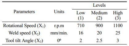
This heating softens the material and the movement of it takes place due to tool travel resulting in fine grains at the joint. The parameters employed while making the joints are given in Table 3.
Mechanical property Evaluation:
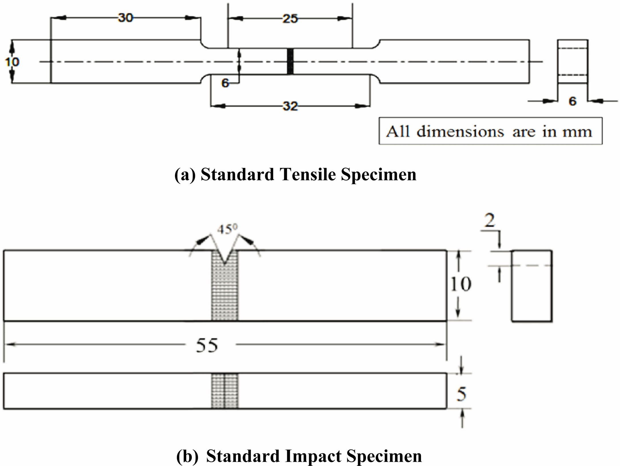
The joints have been subjected to mechanical property evaluation. The tensile test sample employed is as per ASTM E08 standard Fig. 2a while the impact test sample preparation is done as per ASTM E23 standard as shown in Fig. 2b. Micro hardness of the joints have been evaluated at a load of 100 gmf at an interval of 0.5 mm across the joint. The welded samples s prepared form FSW process were cut into test samples by wire cut EDM machines. The welding process was conducted employing the combination of parameters in such a way that randomness consistency and accuracy have been maintened completely.
Metallography and Scanning electron microscopy
The weld samples here mounted in bakelite and polishing was performed using SiC papers. Olympus optical microscopewere etched with ethanol based picric acid solution to capture the microstructure at the weld joint. The fractured features from the tensile test are examined under scanning electron microscope inunetched condition at various magnifications and the fracture evaluation is carried out.
(EDAX) Energy dispersive X-ray spectroscopy
It is employed for elemental analysis in the stir zone of the specimen to identify the compound formation occur at the weld nugget zone.
Taguchi Method
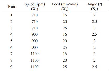
Design of experiments by Taguchi method optimizes the process parameters in such a way that the intended quality and the achieved targets stay close and the process often being termed as parameter design. In this investigation L9 orthogonal array [Table 4] of Taguchi is being undertaken for the experimentation [14, 15].
TOPSIS Method
Technique for order of preference by similarity to ideal solution (TOPSIS) is a multicriteria decision analysis method resting on the concept that the alternatives will be having shortest geometric distance from positive ideal and longest from negative ideal solutions. Normalization is carried out for the multi characteristic responses and getting realistic form of modeling by tradeoff between poor and good results.
Results and Analysis
The experimentation has been conducted by employing the L9 Taguchi OA. To eliminate error and bias the runs are conducted at random. Five responsible variables namely ultimate tensile strength (UTS), Yield strength (Ys), elongation percentage (El), Impact toughness (Is) and Vickers micro hardness (Hv) were measured and compiled in Table 5a.
Lower the better criterion is employed for elongation and hardness whilehigher the better is employed for the remaining responses and accordingly signal noise (S/N) ratios are computed as illustrated in Table 5b.
After normalizing the data have been weighted with 35% each to properties namely UTS and Is and a weightage of 10% is given to the remaining responses while carrying out the TOPSIS analysis in Table 5c.
For comparative evaluation FSW joints of AZ 91D Mg alloy also made without the addition of boron powder at the joint and the mechanical properties have been measured [Table 6].
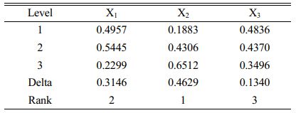
The closeness coefficients computed from TOPSIS analysis [Table 5c] have been subjected to Analysis of Means and Analysis of Variance as per Taguchi method and are shown in Table 7 and Table 8 respectively.

|
Fig. 1 Friction stir welding Machine. |
|
Fig. 2 Tensile AndImpact Test Samples. |
|
Table 5 (a) Mechanical Properties of AZ 91D Mg alloy FSW joints with boron powder. |

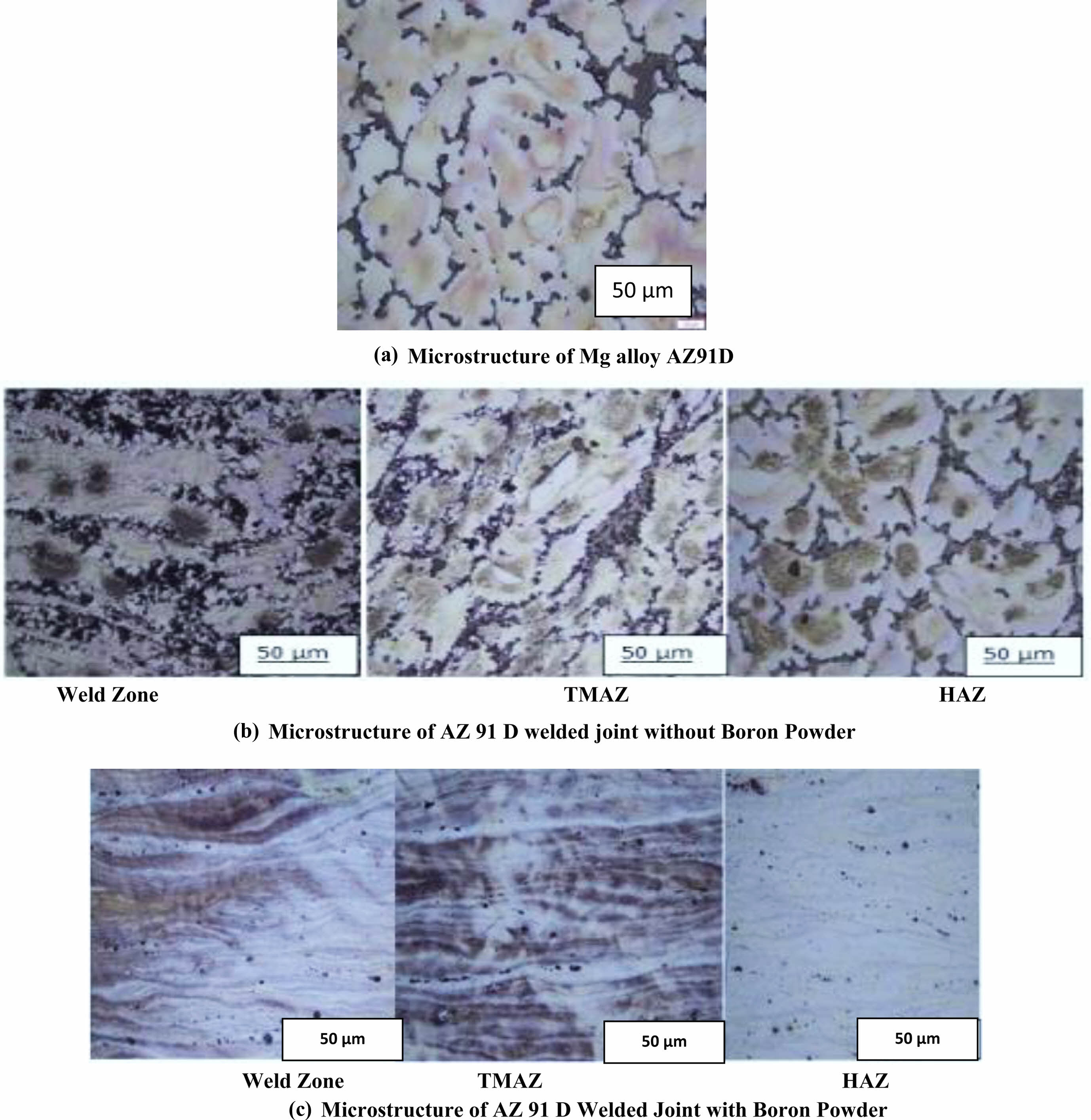
The yield strength and ultimate tensile strength of the welded joints when boron powder was in place at the interface are higher than the joints made without boron powder. The ultimate tensile strength has increased from 114 MPa, when boron was not present, to 199 MPa when boron was at the interface. The microstructure of the weld nugget zone of the joints without boron powder and with boron powder is shown in Fig. 3. In the given figures, Fig. 3a. shows the base material having large grains, Fig. 3b. shows the material after welding where the weld grains are fine due to dynamic recrystallization compared to parent material and in Fig. 3c. free boron is formed at the grain boundaries. The heat generated in the process is conducted from weld zone to HAZ through the AZ91 magnesium alloy and boron powder. As the melting temperature of the boron is more than the parent metal it remained as free powder at grain boundaries and helping in improving the mechanical strength.
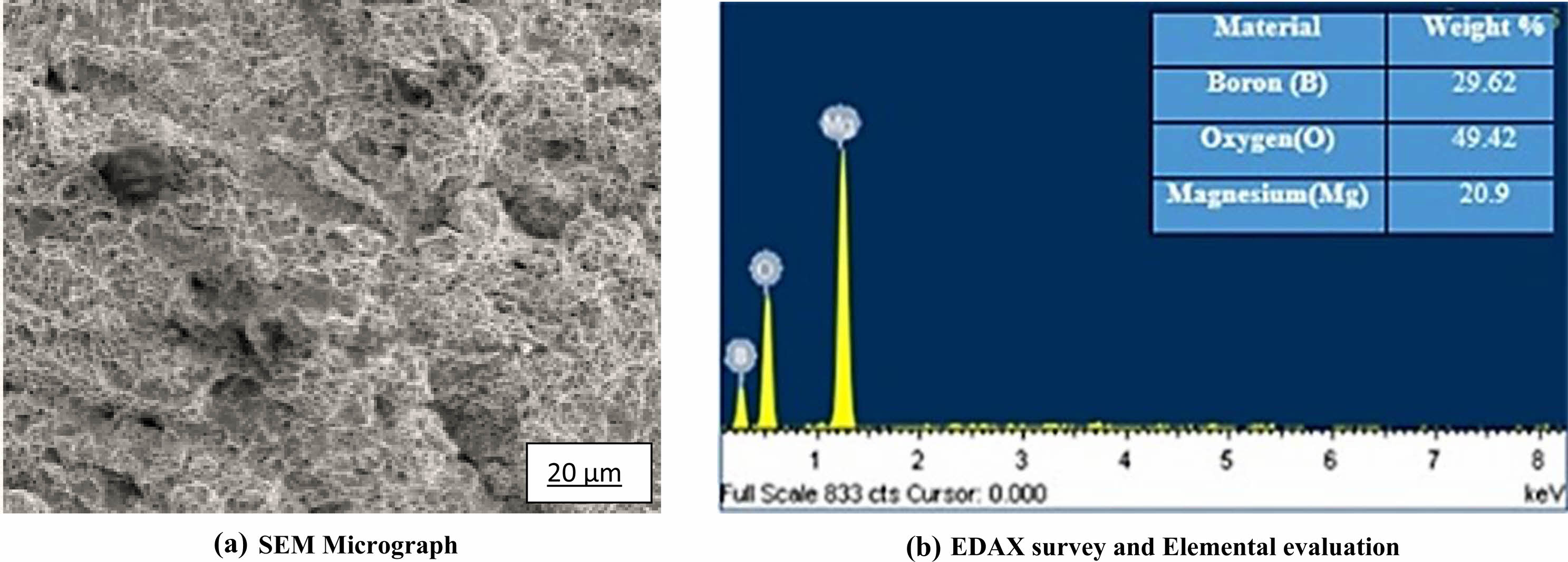
The average grain size in weld zone is fine compared to the TMAZ and HAZ zones due to dynamic recrystallization occurred due to the tool rotation [12]. Also the boron has caused the grain refinement and subsequent improvement of mechanical properties [13]. The fractured surface is observed under scanning electron microscope and verified for the precipitation of compound formation using EDAX as shown in Fig. 4.
It is found that sporadic B2O3 compounds are formed at the weld nugget and their mixing with MgO causes the solid with textural property variation together with a change in strength distribution [16]. The elongation has also increased to 2.15% when boron application is undertaken in welding. Due to rotation of tool, severe plastic deformation occurs which increases the dislocation density preventing the grain boundary from slipping. The atomic size of boron is smaller as compared to magnesium and hence occupied interstitially in the matrix and pinned the movement of dislocation and grain boundary. The impact toughness of the joint with boron addition has also increased to 4.0 Joules due to the presence of boron.
The temperature increases with tool rotation and reaches to an extent of 500 oC. In the presence of boron the precipitation hardening taking place causing the variation in hardness across the weld zone through TMAZ and HAZ occurred due to the microstructural changes taken place [17]. The hardness survey across the weld zone to base metal for a typical weld joint is shown in Fig. 5. The hardness is changed in the weld zone compared to base metal.
The Analysis of Means (ANOM) computed in Table 7 are plotted for variation against the levels of each of the process parameters as shown in Fig. 6.
Optimal parameters condition [Table 9] is identified by selecting the higher the better criterion for the closeness coefficient. The contribution of each of the parameters on the chosen response is computed employing Yate’s algorithm for ANOVA [14] andis shown in the Table 8.
The contribution of each of the parameters on the chosen response is computed and is shown in the Table 8. The weld feed is playing major role by an extent of 41.96% and speed is operating to a tune of 31.34% while the tilt angle is governing the least to a minimum of 3.13% in the variation of the responses.
The optimal responses are as per the run 6 of the results when TOPSIS analysis is conducted with weightages are attributed. However the functional requirement in sitedecides the weightage and the optimally can be chosen accordingly.
|
Fig. 3 Microstructure of Metal and its Welds. |
|
Fig. 4 SEM micrograph & EDAX survey |

|
Fig. 5 Hardness of a weld joint. |

|
Fig. 6 Analysis of Means. |
• The multi criterion responses can be best handled by TOPSIS analysis with weightages.
• The weld feed is governing about 42% in the achievement of all responses optimally.
• Boron helped in increasing the mechanical properties considerably as compared to base friction welding joints.
The authors thank the management of Koneru Laksmaiah Educational Foundation and Vidya Jyothi Institute of Technology for the support extended during this current research work.
- 1. G.A. Nourollahi, M. Farahani, A. Babakhani, and S.S. Mirjavadi, Mater. Res. 16[6] (2013) 1309-1314.
-

- 2. L. Liu, D. Ren, and F. Liu, Mater (Basel) 7[5] (2014) 3735-3757.
-

- 3. X. Cao, M. Jahazi, J.P. Immarigon, and W. Wallace, J. Mater. Process. Technol. 171[2] (2006) 188-204.
-

- 4. F. Czerwinski, Welding and Joining of Magnesium Alloys (2011).
-

- 5. K. Rajesh Kumar, Dama. Kiran Kumar, and V.V. Satyanarayana, Int. J. Mech. Prod. Eng. Res. Dev. 10[2] (2020) 591-600.
-

- 6. C.D. Sorensen, Materials park Volume 6A (2011).
- 7. R.S. Mishra and Z.Y. Ma, Material Science Engineering and Research 50[1-2] (2005) 1-78.
-

- 8. J.Q. Su, T.W. Welson, and C.J. Sterling, Philos. Mag. 86 (2006) 1-24.
-

- 9. C.G. Rhodes, M.W. Mahoney, W.H. Bingel, and M. Colabrese, Script Material 48[10] (2003) 1451-1455.
-

- 10. J. Yang, D. Wang, B.L. Xiao, D.R. Ni, and Z.Y. Ma, Metall. Mater. Trans. A 44[1] (2013) 517-530.
-

- 11. M. Tabasi, M. Farahani, M.K. Besharati Givi, M. Farzami, and A. Moharami, Int. J. Adv. Manuf. Technol. 86 (2016) 705-715.
-

- 12. S.H.C. Park, Y.S. Sato, and H. Kokwa, J. Mater. Sci. 38[21] (2003) 4379-4383.
-

- 13. Shuo Zhang, et. al., Materials 12[7] (2019) 1100(1-13).
-

- 14. R.K. Roy, A primer on the Taguchi method, Van N Reinhold, NY, (1990) 100-154.
- 15. Phiilip J. Ross, Taguchi Techniques for Quality Engineering, McGraw-Hill preferred, 2nd Edition, (1995).
- 16. M.A. Mramendia, V. Borau, C. Jimenez, J.M. Marinas, A. Parras, and F.J. Urbano, J. Mater. Chem. 3[9] (1999) 819-825.
-

- 17. Tatiana Orsulovia and Peter Pakek, Production Engineering Archives 18 (2018) 46-49.
-

- 18. B. Ravinder Reddy, R.V. Rangaraju, A.B. Ibrahim, MFBC Ku, Transact. of Indian Inst. of Metals 70 (2017) 1005-1017.
-

 This Article
-
2023; 24(3): 439-445
Published on Jun 30, 2023
- 10.36410/jcpr.2023.24.3.439
- Received on Aug 30, 2022
- Revised on Sep 20, 2022
- Accepted on Oct 12, 2022
 Services
Shared
 Correspondence to
- K. Rajesh Kumar
-
Research Scholar, Department of Mechanical Engineering, Koneru Lakshmaiah Education Foundation, Vaddeshwaram, Andhra Pradesh, India
Tel : 08413-235300 Fax: 08413-235300 - E-mail: krajeshkumarphd@gmail.com





 Copyright 2019 International Orgranization for Ceramic Processing. All rights reserved.