- Reliability characteristics of high-capacity multilayer ceramic capacitors according to highly accelerated life test
Chang Ho Lee and Jung Rag Yoon*
R&D Center, Samwha Capacitor, Yong-In, Korea
This article is an open access article distributed under the terms of the Creative Commons Attribution Non-Commercial License (http://creativecommons.org/licenses/by-nc/4.0) which permits unrestricted non-commercial use, distribution, and reproduction in any medium, provided the original work is properly cited.
Advancement of semiconductor technology, introduction of 5G networks, and expansion of the electric vehicle market have gradually increased the demand for highly reliable multilayer ceramic capacitors (MLCCs) owing to requirement of miniature electronic equipment. Efforts to achieve high reliability are underway to improve the properties of materials such as dielectrics, internal electrodes, and external electrodes. However, there are few studies on appropriate measurement methods for evaluating reliability, deterioration mechanisms, and lifetime calculations. In this study, an MLCC device was made to deteriorate through the highly accelerated life test (HALT), and the capacitance–voltage (C–V), temperature coefficient of capacitance (TCC), and current–voltage (I–V) characteristics were analyzed according to the elapsed time of deterioration. In addition, the activation energy (Ea) and voltage acceleration coefficient (n) were extracted through a lifetime prediction experiment, and the results of failure in time (FIT) and mean time to failure (MTTF) indicated the lifetime of the MLCC. From the results, it was confirmed that the insulation resistance evaluated using the HALT is an important factor for confirming the reliability and lifetime characteristics of MLCCs
Keywords: Multilayer ceramic capacitor, Highly accelerated life test, Failure in time, Mean time to failure
Multilayer ceramic capacitors (MLCCs) based on BaTiO3 dielectric materials are increasingly being used in autonomous vehicles, the Internet of Things (IoT), 5G networks, and aerospace engineering [1, 2]. To meet the needs of various usage environment fields, research on miniaturization and voltage range enhancement of MLCCs using Ni internal electrodes is gaining momentum [3-5]. BaTiO3-based MLCCs on Ni electrodes are sintered in a reducing or hydrogen atmosphere because of the ease of oxidation of Ni electrodes. Thus, it is considered that multiple oxygen vacancies remain in the dielectric BaTiO3 layer of MLCCs even after the re-oxidation process [6-8]. Because the reliability of MLCCs is a very important factor in various electronic devices, the highly accelerated life test (HALT) is widely used to investigate the electrical reliability of MLCCs at high temperatures and voltages [9-11]. During the HALT, oxygen vacancies in the BaTiO3 active layer become positively charged and move to the cathode, as expressed in equation (1) [12-14].

Therefore, the concentration of oxygen vacancies near the cathode increases. The increased oxygen vacancies induce electron transfer to the cathode with a direct current (dc) bias, reducing the insulation resistance of the MLCC and limiting its lifetime. Therefore, it is important to explain the mechanism of insulation resistance deterioration in MLCCs. In this study, electrical characteristics such as the capacitance–voltage (C–V), temperature coefficient of capacitance (TCC), and current–voltage (I–V) measurements of the deteriorated devices over time after degradation of MLCC devices are investigated through the HALT. Finally, failure in time (FIT) and mean time to failure (MTTF)-like life predictions are made through the HALT, and the results of highly reliable MLCC life are presented.
Sample Preparation
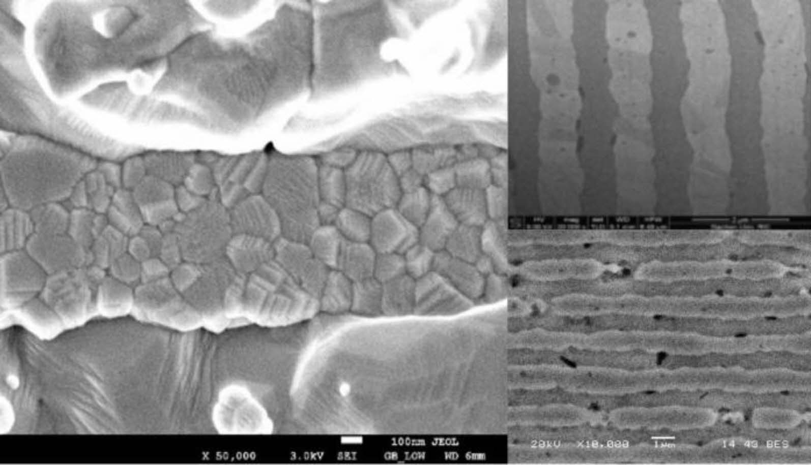
In this experiment, a dielectric composition having electrical characteristics, environmental test characteristics, long life, and high-reliability characteristics of a multilayered ceramic capacitor for an electric vehicles was applied. BaTiO3 was used as a dielectric ceramic raw material, and additives such as MgO, BaCO3, SiO2, Dy2O3, Y2O3, Mn3O4, V2O5 and Cr2O3 having a purity 99.9% or more and particle size (D50) of 50 to 120 nm were used. As BaTiO3 having a size of 120 nm, a dielectric ceramic raw material prepared by a solid state method was used. BaTiO3 was mixed together using toluene/ethanol, and then a PVB (polyvinyl butyral) dissolved in toluene/ethanol was added thereto, followed by preparation of slurries. In the following sequence, the prepared slurries was formed into a dielectric sheet having 0.65 μm by using a casting system. A Ni electrode was printed on the dielectric sheet, and multi-layer structures were formed by stacking dielectric sheet, and then cut, thereby preparing green chips, having a size of 1.0 mm × 0.5 mm × 0.5 mm. The prepared green chips were subjected to binder burnout at 240 ℃ for 42 h, and then sintered under a reducing atmosphere at a temperature of 1160 ℃. After the sintered chip was polished, a Cu electrode was applied and fired to form an external electrode to fabricate a multilayered ceramic capacitors. The size of high-capacity multilayer ceramic capacitor (MLCC) used in this study is 1.0 mm × 0.5 mm × 0.5 mm, with a capacitance of 10 μF and a rated voltage of 6.3 Vdc was used. Fig. 1 shows the results of the scanning electron microscopy (SEM) analysis of 1005 size MLCC internal electrodes and dielectric layers. The average dielectric layer thickness inside the MLCC was 0.65 μm, the number of particles in the dielectric layer was 4 to 5 per unit of thickness, and the Ni internal electrode was stacked with a thickness of 0.8 μm.
HALT Method
The HALT was conducted for 1000 h at 398 K and 10 Vdc (1.5 rated voltage) using a temperature chamber and power supply device. To check the MLCC deterioration characteristics over time in a high-temperature and high-voltage environment, the I–V characteristics were measured at intervals of 0, 100, 300, 600, and 1000 h. The I–V characteristics were measured using a temperature chamber and an electrometer/high resistance meter (B2985A, Keysight). The C–V and TCC characteristics were measured at a measurement frequency of 120 Hz using a precision LCR meter (E4980A, Keysight) and a temperature chamber (S&A 4220A).
Median Lifetime Prediction Method
In the accelerated test of an MLCC, a typical method is a temperature-and voltage-accelerated test. Because the deterioration reaction of MLCC is often accompanied by chemical changes, the rate of deterioration increases as the temperature increases according to the Arrhenius model. In this study, the Arrhenius model, which focused only on the temperature effect, was developed, and the generalized Erying model equation was applied by including stress effects such as voltage and temperature changes [15, 16]. It has been reported that this MLCC acceleration equation according to the temperature and voltage follows the Eyring model well and is defined by equation (2).

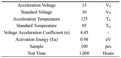
AL = acceleration factor
LN= life under standard conditions.
LA = life under acceleration conditions.
VA = voltage under acceleration conditions.
VN = voltage under standard conditions.
n = Voltage acceleration coefficient
Ea = Activation energy
k = Boltzmann's constant
TN = standard temperature.
TA = acceleration temperature.
Temperature Acceleration Evaluation Method
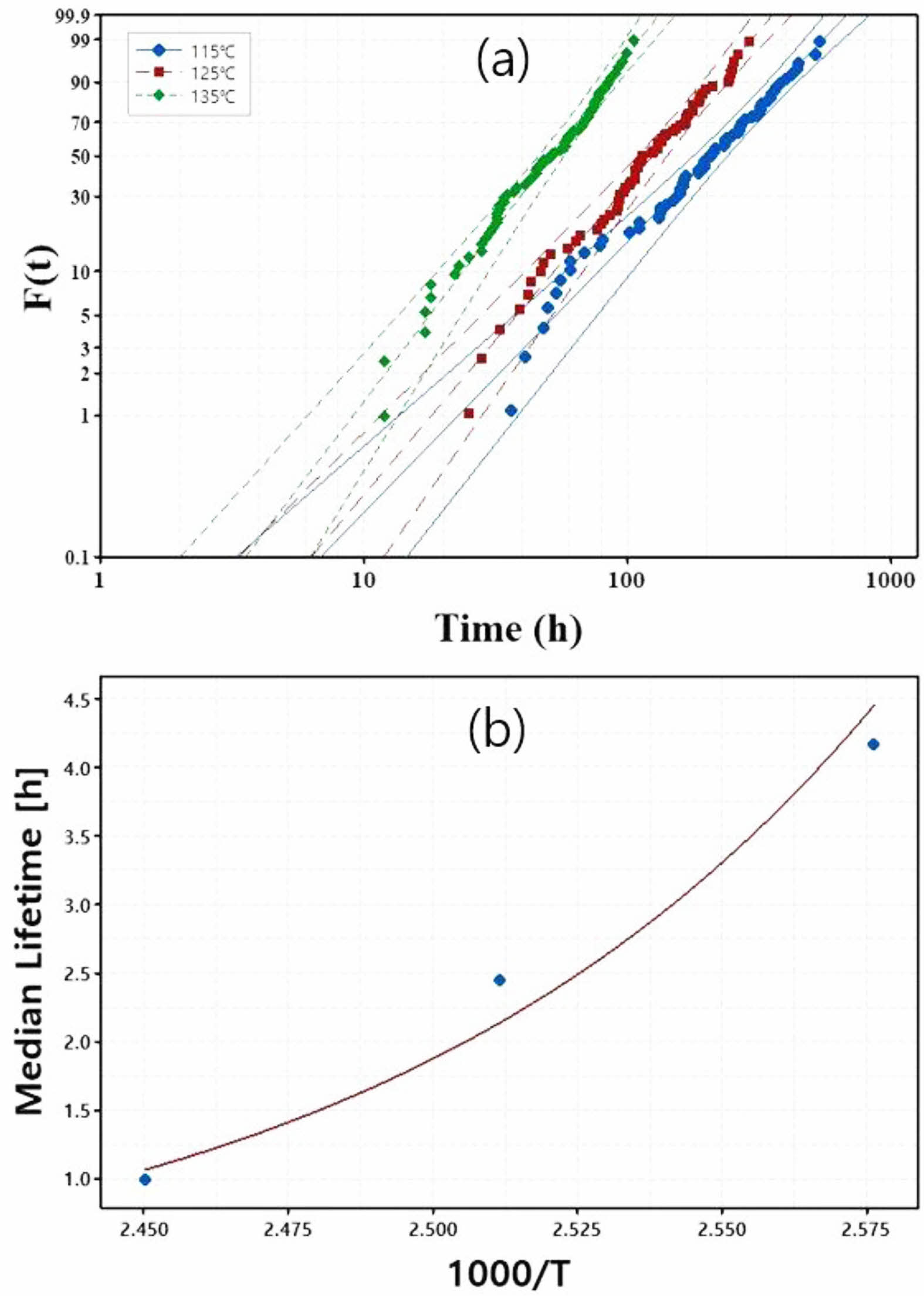
The sample used for the median lifetime prediction evaluation was the same as that used for the HALT. The applied voltage during the test was fixed at 60 Vdc, which is six times the rated voltage (10 Vdc), and the test temperature was set to 388, 398, and 408 K. For the evaluation of life characteristics, the insulation resistance, which is likely to lead to a fatal failure during actual use, was measured, and the failure judgment reference value was set to 1 MΩ. The number of samples was 100 for each condition.
Voltage Acceleration Evaluation Method
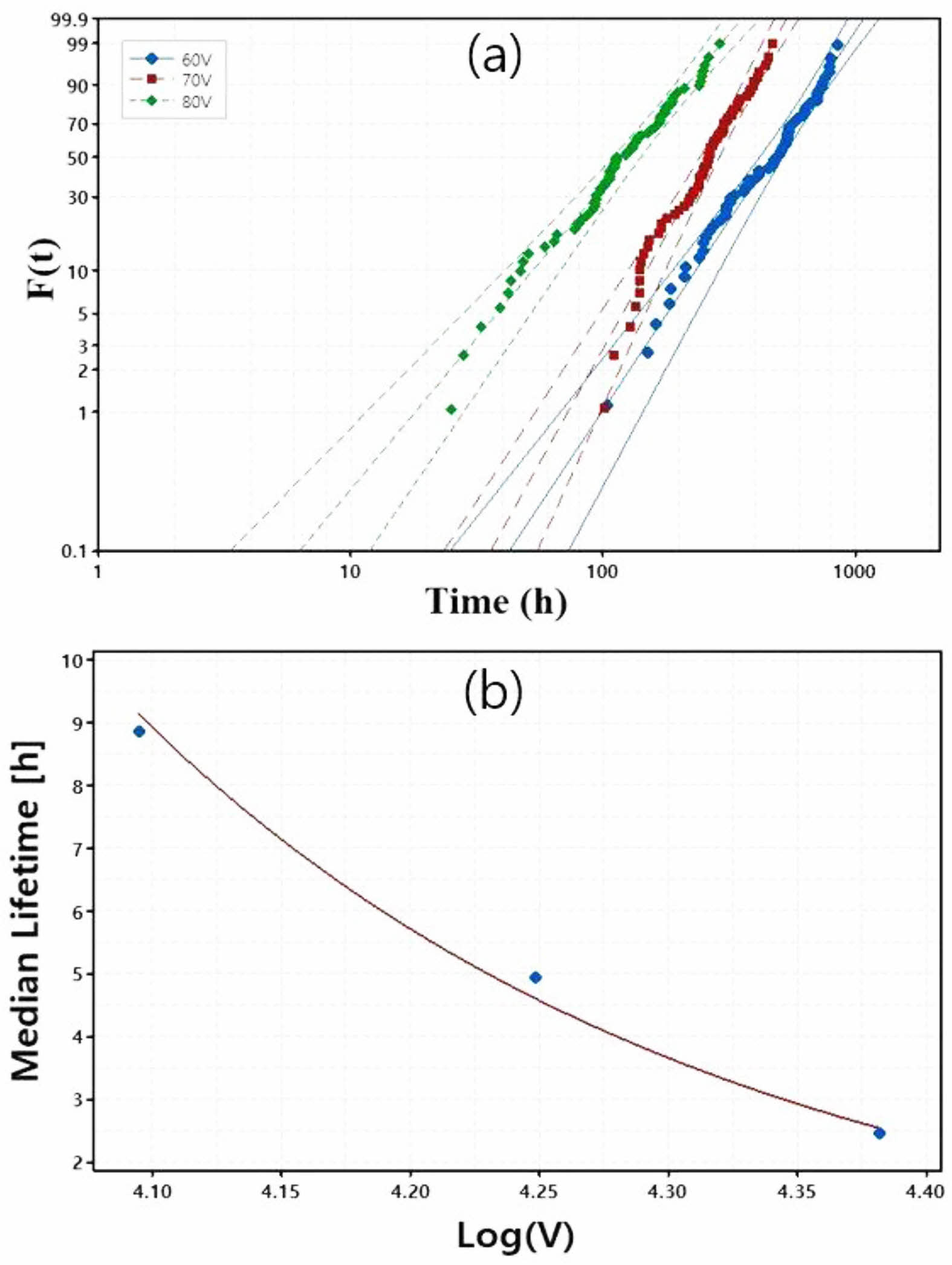
The sample used for the voltage acceleration evaluation employed the same MLCC used for the temperature acceleration test. The test temperature was fixed at 408 K, and the applied voltage was set to three conditions of 60, 70, and 80 Vdc, the number of samples and the failure judgment criteria were the same as those in the temperature acceleration test.
|
Fig. 1 SEM image of the microstructure of the MLCC. |
I–V Curve
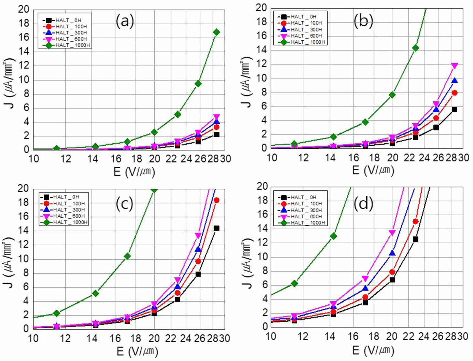
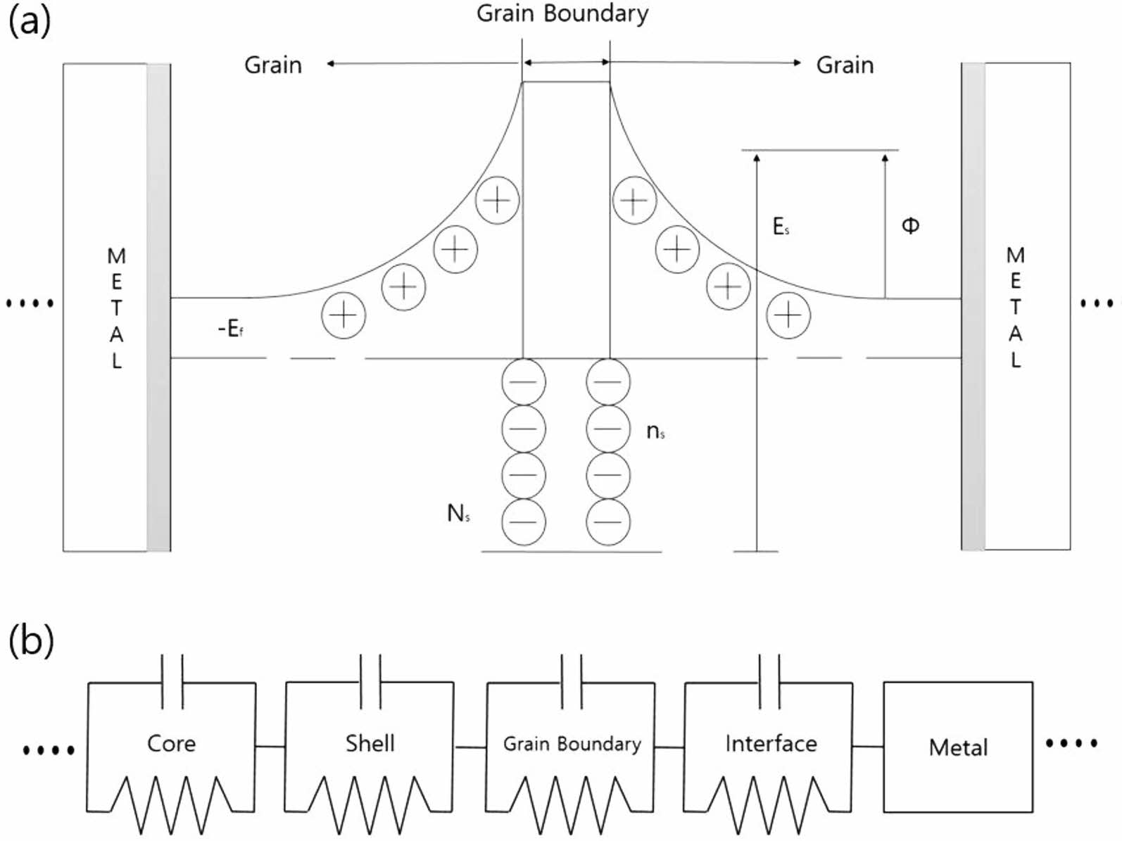
Fig. 2 shows the I–V curve of the MLCC degraded by the HALT with changes in temperature and electric field strength. It can be confirmed that the current density increases as the electric field strength increases, regardless of the measurement temperature. In addition, it was confirmed that the value of the current density increased sharply as the temperature increased, and that the change in MLCC degradation increased based on the HALT time of 600 h. When the high-capacitance BaTiO3-based MLCC is sintered in a reducing atmosphere using H2–H2O mixed gas, the BaTiO3 dielectric ceramic is chemically reduced and has n-type characteristics. As the degradation time increased, the oxygen pores caused electrolytic migration from the anode (+) to the cathode (-) direction, and oxygen defects accumulated on the cathode surface, causing a rapid increase in current density in the high electric field. This phenomenon is believed to be due to Schottky emission, which is similar to conventional insulator conduction. Fig. 3 shows the Schottky emission mechanism and micro-equivalent circuit diagram of the MLCC. As shown in the Schottky emission diagram, there are grains and grain boundaries between the two metals. In such a structure, the grain boundaries act as a barrier for charge transfer. However, when the thickness of the grain boundary decreases or the grains deteriorate owing to the occurrence of oxygen vacancies, it is presumed that charge transfer becomes effective, and the insulation resistance decreases. In addition, deterioration of each microstructure ultimately lowers the potential barrier and reduces insulation resistance, as evidenced by the schematics of cores, shells, grain boundaries, interfaces, and metals.
C–V and TCC Curve
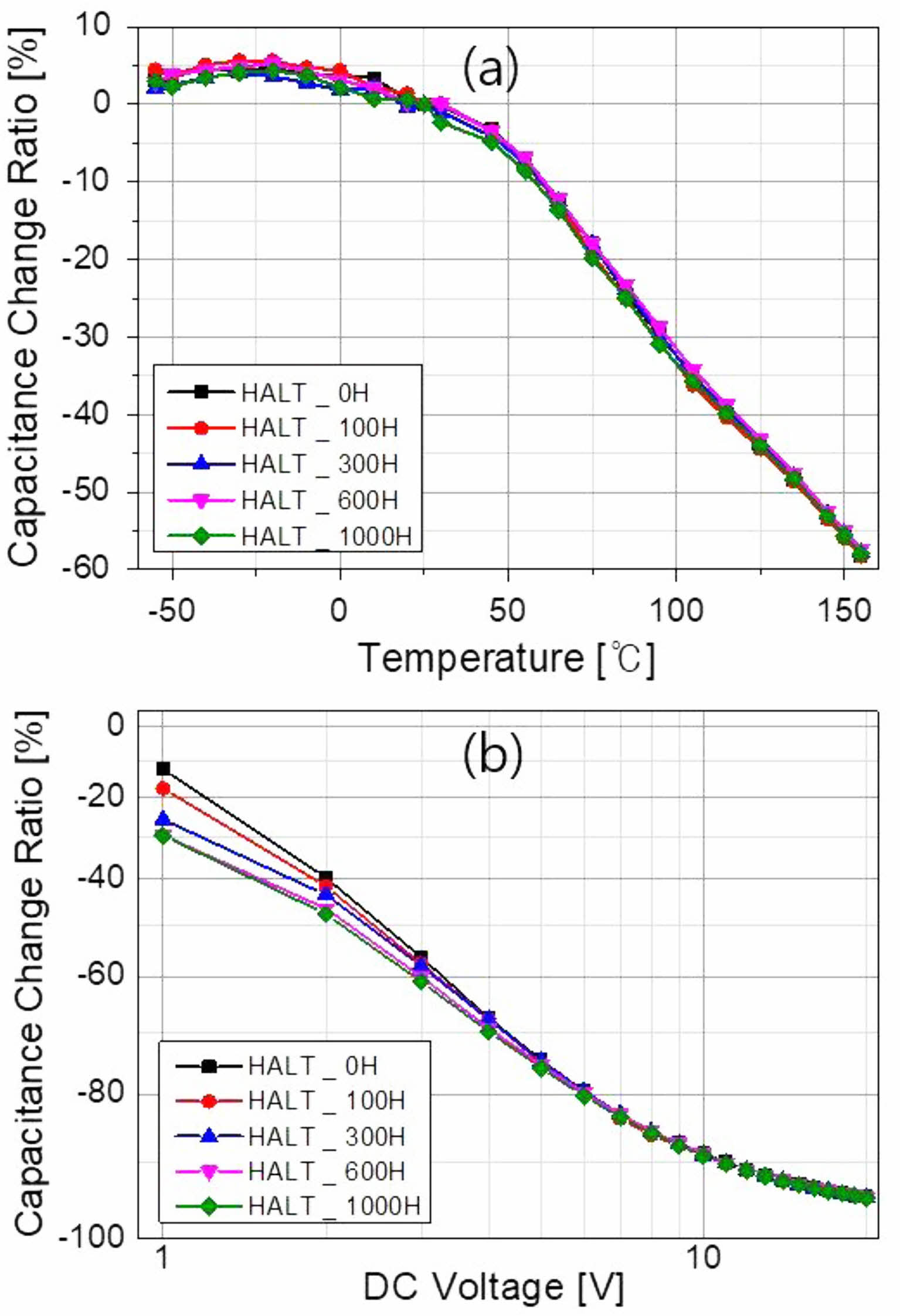
Fig. 4 shows the C–V and TCC characteristics of the deteriorated MLCC. As can be seen in Fig. 4(a) and (b), there was no remarkable difference in the electrical characteristics according to the elapsed time of deterioration. No evidence of MLCC deterioration can be confirmed from the results of the C–V characteristics, and a small capacitance decrease due to deterioration can be confirmed from the results of the TCC characteristics in the low electric field region. However, when this capacitance reduction is applied at a voltage equal to or higher than the rated voltage, the deteriorated MLCC cannot be distinguished. When examining the three measurement methods, it can be concluded that the measurement method of the I–V characteristics is the most suitable for selecting the MLCC element that has been initially deteriorated.
Median Lifetime Prediction
Temperature Acceleration Evaluation
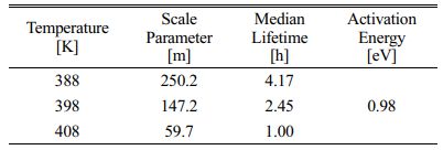
The results of Weibull analysis under the test conditions at each temperature are shown in Fig. 5(a), and the results of the analysis using the Arrhenius model by applying the median lifetime estimated from the Weibull analysis are shown in Fig. 5(b). Table 1 summarizes the results of each parameter, and the activation energy (Ea) value was calculated at 0.98 eV. The Ea values of BaTiO3-based dielectric capacitors reported to date are in the 1.0-1.45 eV range. In this study, the calculated Ea value was below 0.98, which is considered to be within the range of experimental error.
Voltage Acceleration Evaluation
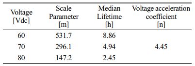
For the voltage acceleration evaluation sample, the same MLCC used for the temperature acceleration test was applied, and the test temperature was fixed at 408 K. The applied voltage was set to three conditions: 60, 70, 80 Vdc. The number of samples and failure judgment criteria were the same as those in the temperature acceleration test. The results of the Weibull analysis for each voltage acceleration test are shown in Fig. 6(a), and the relationship between the applied voltage and average life obtained from these results is shown in Fig. 6(b). From the results shown in Fig. 6, the voltage acceleration coefficient (n) was 4.45. The values of each parameter obtained from the tests and analyses are summarized in Table 2. This makes it possible to predict the life under actual usage conditions using the voltage acceleration coefficient. Table 3 summarizes the MLCC lifetime calculation parameters, and Table 4 summarizes the calculated MLCC lifetime calculation results. Finally, the failure in time (FIT) value was 61.97, and the mean time to failure (MTTF) value was 1,842 years, using which the expected lifetime result could be calculated.
|
Fig. 2 I–V characteristic graphs according to the measured temperature of MLCC deteriorated by HALT. (a) 323 K, (b) 348 K, (c) 373 K, and (d) 398 K. |
|
Fig. 3 Schematic diagram of insulation resistance deterioration mechanism: (a) Schottky emission mechanism; (b) micro equivalent circuit diagram of MLCC. |
|
Fig. 4 C–V and TCC characteristic graphs of MLCC deteriorated by HALT: (a) C–V; (b) TCC. |
|
Fig. 5 Temperature acceleration evaluation result: (a) cumulative failure rate Weibull distribution at each test temperature; (b) median lifetime Arrhenius plot. |
|
Fig. 6 Voltage acceleration evaluation results: (a) cumulative failure rate Weibull distribution at each test voltage; (b) median lifetime Eyring plot. |
|
Table 1 Weibull analysis parameters and activation energy for temperature acceleration. |
|
Table 2 Weibull analysis parameters and voltage acceleration coefficients for voltage acceleration. |
In this study, HALT evaluation was performed, and the TCC, C–V, and I–V characteristics of the MLCC device were made to deteriorate with time. In the TCC and C–V measurements, it was difficult to distinguish the difference due to deterioration, and in the I–V measurement results, it was found that the leakage current increased after 600 h as the deterioration time and measurement temperature increased. These results indicate that I–V measurements are more advantageous than TCC and C–V measurements in the process of selecting the initial defective products. The MLCC degradation was explained using the Schottky emission mechanism and micro equivalent circuit diagram. It was found that the insulation resistance decreased due to deterioration at the grain boundary and interface inside BaTiO3, and the leakage current increased as the electron movement increased. Furthermore, in order to predict the lifetime of the MLCC device, a temperature and voltage acceleration test was performed, and as a result, an activation energy (Ea) value of 0.98 eV and a voltage acceleration coefficient value of 4.45 were obtained. Finally, as a result of calculating the estimated lifetime using the Ea and n values, we were able to predict an FIT value of 61.97 and MTTF value of 1,842 years, indicating a highly reliable life.
This work was supported by a National Research Foundation of Korea (NRF) grant funded by the Korean government (MSIT) (NRF-2021M1A3B2A01076907).
- 1. J.R. Yoon, K.M. Lee and S.W. Lee, Trans. Electr. Electron. Mater 10[1] (2009) 5-8.
- 2. Sada, Takao, and Nobuyoshi Fujukawa, Jpn. J. Appl. Phys, 56[10S] (2017) 10PB04.
-

- 3. G. Dale, M. Strawhorne, D.C. Sinclair and J.S. Dean, J. Am. Ceram. Soc. 101[3] (2018) 1211-1220.
-

- 4. H.L Ana Maria, A.G. Juan Antonio, G.F. Sophie, N.Q. Roman, D. Pascal, T. Christophe, D. Bernard and V.N. Zarel, Mater 11[10] (2018) 1900.
- 5. H. Gong, X. Wang, W, S. Zhang, H. Wen and L. Li, J. Eur. Ceram. Soc. 34[7] (2014) 1733-1739.
-

- 6. Y. Wang, L. Li, J. Qi, Z. Ma, J. Cao, Z. Gui, Mater. Sci. Eng. 99[1-3] (2003) 378-381.
-

- 7. C.C. Lin, W.C.J. Wei, C.Y. Su and C.H. Hsueh, J. Alloys. Compd. 485[1-2] (2009) 653-659.
-

- 8. M.G. Kim, B.H. Lee and T.Y. Yun, IEEE. Trans. Compon. Packaging. Manuf. Technol. 2[6] (2011) 1012-1020.
-

- 9. X. Xu, A.S. Gurav, P.M. Lessner and C.A. Randall, IEEE. Trans. Industr. Inform. 58[7] (2010) 2636-2643.
-

- 10. M. Randall, A. Gurav, D. Skamser and J. Beeson, Carts. Confer. Compo. Tech. Ins. (2003) 134-140.
- 11. V.I. Hernandez, D.I. Garcia-Gutierrez, J.A. Aguilar-Garib and R.J. Nava-Quintero, Ceram. Int. 47[1] (2021) 310-319.
-

- 12. Y. Saito, T. Nakamura, K. Nada and H. Sano, Jpn. J. Appl. Phys. 57[11S] (2018) 11UC04.
-

- 13. K. Suzuki, T. Okamoto, H. Kondo, N. Tanaka and A. Ando, Jpn. J. Appl. Phys. 113[6] (2013) 064103.
-

- 14. K. Nishida, H. Kishi, M. Osada, H. Funakubo, M. Nishide and T. Yamamoto, Jpn. J. Appl. Phys. 48[9S1] (2009) 09KF11.
-

- 15. W. Jia, Y. Hou, M. Zheng, Y. Xu, X. Yu, M. Zhu and J. Xing, J. Am. Ceram. Soc. 101[8] (2018) 3468-3479.
-

- 16. D. Brown, IEEE. Pan. Pacific. (2018) 1-6.
-

 This Article
-
2022; 23(6): 794-798
Published on Dec 31, 2022
- 10.36410/jcpr.2022.23.6.794
- Received on Mar 4, 2022
- Revised on Jun 7, 2022
- Accepted on Jun 18, 2022
 Services
- Abstract
introduction
experimental method
result and discussion
conclusion
- Acknowledgements
- References
- Full Text PDF
Shared
 Correspondence to
- Jung Rag Yoon
-
R&D Center, Samwha Capacitor, Yong-In, Korea
Tel : +82-31-330-5765 Fax: +82-31-332-7661 - E-mail: yoonjungrag@samwha.com



 Copyright 2019 International Orgranization for Ceramic Processing. All rights reserved.