- Microstructural evolution of chemically vapor-deposited tantalum carbide at elevated temperature
Jangwon Hana,b, SangMin Jeongc, Ji Yeon Parkb, Hyun-Geun Leeb, Weon-Ju Kimb, Chan Parka and Daejong Kimb,*
aSchool of Materials Science & Engineering, Seoul National University, Seoul 08826, Republic of Korea
bNuclear Materials Development Division, Korea Atomic Energy Research Institute, Daejeon 34057, Republic of Korea
cSiC Division, HANA Materials, Asan 31413, Republic of KoreaThis article is an open access article distributed under the terms of the Creative Commons Attribution Non-Commercial License (http://creativecommons.org/licenses/by-nc/4.0) which permits unrestricted non-commercial use, distribution, and reproduction in any medium, provided the original work is properly cited.
Tantalum carbide (TaC), one of the ultra-high temperature ceramics, was chemically vapor-deposited at 1100 - 1300 oC in a TaCl5-C3H6-H2 system. Microstructural evolution of TaC was evaluated after heat treatment at 1850 oC for 4 hours. Various tantalum carbides with different orientation and microstructure were obtained depending on the deposition temperature and the position. Crystallophic preferred orientation of the TaC changed from highly oriented (111) and (200), to random texture, as deposition temperatures increase. The continuous feed of TaCl4 powders using screw-driven feeder led to the fluctuation of TaCl4 partial pressure during the deposition process, resulted in a low crystallinity and formation of micropores. A dense TaC was only obtained at the high partial pressure of TaCl5. Heat treatment dramatically enhanced crystallinity but micropores were coalesced into large pores along grain boundaries. The influence of crystallophic orientation and microstructure on microstructural evolution and hardness during heat treatment were investigated
Keywords: Tantalum Carbide, Chemical Vapor Deposition, Heat treatment, Orientation
Refractory material carbides (ZrC, HfC, TaC, NbC, etc.) shows good performance in ultra-high temperature regions with their thermal/mechanical properties.[1-5] Especially, tantalum carbide (TaC) has drawn attention among refractory metal carbides due to their great performance with extremely high melting point (3983 ºC), high modulus (537 GPa), high hardness (15-19 GPa) and good resistance to chemical attack [6, 7]. However, the ablation properties of TaC were found to be poor at high temperature. Nowadays, TaC materials are applied in semiconductor applications such as replaceable reactor components like ceramic susceptors. Most of the susceptors for Chemical Vapor Deposition-Silicon Carbide (CVD-SiC) or Metalorganic Chemical Vapor Deposition-Gallium Nitride (MOCVD-GaN) epitaxial growth uses graphite susceptors. In these processes, ceramic susceptors requires two characteristics, such as high temperature stability and chemical resistance. Required property remains by the epitaxial growth performance are produced in the high temperature region (1500-1700 ºC) using SiH4 gas with repetition. TaC coated graphite susceptors show stable performance under SiH4 exposure and do not form any other phases with high temperature stability [8, 9].
Various methods exist to fabricate TaC materials, including Hot Isostatic Pressing (HIP) [10], Hot Pressing (HP) [11], the molten salt method [12] and Spark Plasma Sintering (SPS) [13]. Most of the sintering processes require additives for densification. Also, for practical applications, it is difficult to form complex shapes. So, research focuses of TaC fabrications are on coating process. The most common coating processes are hot-filament CVD [14], Sputtering [15, 18], Metal Organic CVD (MOCVD) [17], Vacuum Plasma Spray (VPS) [16], Pulsed Laser Deposition (PLD) [19], Solid State diffusion [20], Chemical Vapor Infiltration (CVI) [21, 22] and Low Pressure Chemical Vapor Deposition (LPCVD) [23-26]. PLD and Sputtering have advantages of deposition temperature, which is lower than that in CVD methods. However, thickness of the PLD fabricated film is very thin, with low yield, and this method has limits in terms of substrate selection. Also, sputtering has a thicker film and a higher hardness value than have been seen in other report; however, this method has step coverage problems. On the other hand, CVD TaC has dense and conformal structures which lowers the gas permeability. It can prevent contamination from the coating materials because high purity TaC can be obtained by a CVD process. In addition, it can be uniformly deposited on large scale and complex shaped substrates such as susceptors for semiconductor.
In our previous research, Kim et al. [26] showed the deposition conditions for TaC at 1300 ℃ with optimum C3H6/TaCl5 ratio. The partial pressure of TaCl5 affects the microstructure and texture coefficient of the film. Also, the C3H6/TaCl5 ratio is important for the deposition microstructures [25]. Normally, in higher temperature regions, the film formation is determined by the diffusion kinetics [27-29]. When the TaCl5 feeding rate was fixed and C3H6 amount decreases, the C3H6/TaCl5 ratio became lower and excess Ta was supplied during the deposition and forms Ta+α-Ta2C. On the other hand, with the increase of C3H6, excess carbons are supplied on the film, showing the phase change to α-Ta2C, ζ-Ta4C3 and TaC1-x. The ζ-Ta4C3 phases are transition phases between TaC1-x and α-Ta2C. Also, the microstructural behaviors are different by the phase compositions. The ratio change of C3H6/TaCl5 controls the microstructure of the TaC material [26, 30].
In this study, we have fabricated TaC using TaCl5-C3H6-H2 CVD method with different deposition variables. The changes in microstructure and phase after heat treatment of TaC obtained at various deposition conditions were characterized by XRD (X-Ray Diffraction) and SEM (Secondary Electron Microscopy). The influence of microstructural evolution and phase on hardness was discussed.
TaC thin film was deposited using the TaCl5-C3H6-H2 chemical vapor deposition (CVD) system. Detailed fabrication procedures followed those of Kim et al. [26] TaC was deposited on a 2-inch disc type graphite substrate. Source material for Ta of TaC was TaCl5 powder (>99.99%, STREM CHEMICALS) and, for the carbon source, C3H6 (99.99%) was used. For continuous powder feeding, a screw feeder was used. The temperature of the sublimation chamber was 240 ºC. The mixing heater temperature was 400 ºC. The deposition was performed at 1100-1300 ºC. H2 carrier gas was used with flows of C3H6 of 4900 sccm and 100 sccm. A reference specimen, deposited by chemical vapor deposition above 2000 ºC, was used for comparison. Different deposition positions included 4950 sccm of H2 and 50 sccm of C3H6, and materials were placed 20 cm away from the gas outlet. The intervals for the specimens were 5 cm each. Heat treatment of the film was performed at 1850 ºC for 4 hours under Ar condition. The temperature of heat treatment was to observe the high temperature stability of the film. Also, to compare with the commercialized TaC fabricated at high temperatures.
After the fabrication process, X-Ray Diffraction (XRD, D8 Discover, Bruker AXS, Germany) analysis was carried out to identify the original phases and the phase changes due to heat treatment. A cross section of the film was used to observe the microstructure by Field-Emission Scanning Electron Microscope (FE-SEM, FEI, Netherland). Mechanical properties were measured by nano-indenter (CSM Instruments, USA) at 10 points.
Crystallographic Orientation with different deposition temperature and positions
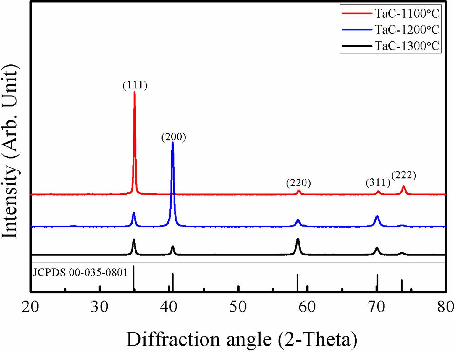
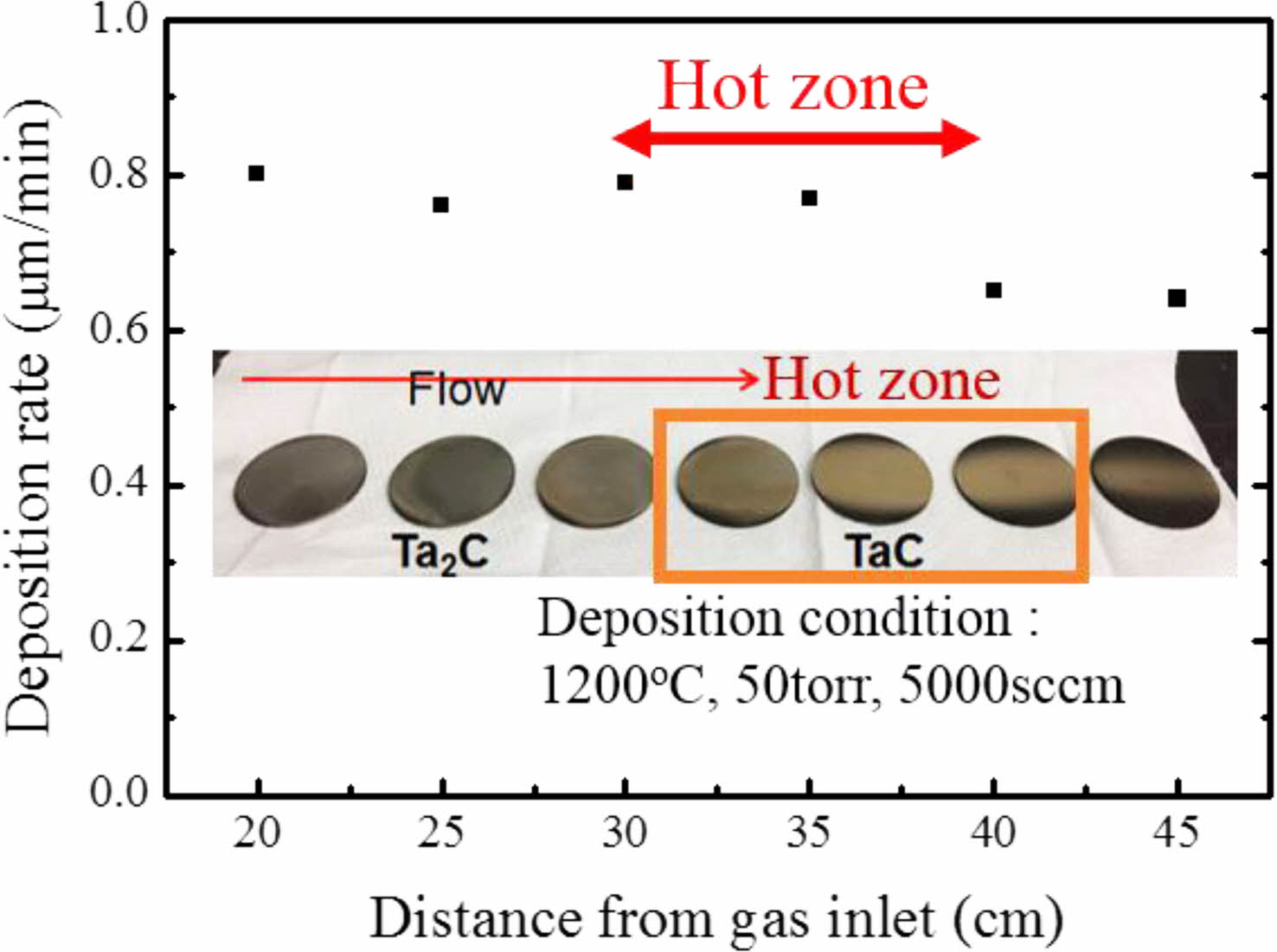
Fig. 1. Shows the XRD results of TaC deposited by Chemical Vapor Deposition (CVD) method. TaC films showed different peak intensities with the change of deposition temperature. The film deposited at 1100 ºC shows highly oriented (111) TaC peaks and, at 1200 ºC, (200) was the highly oriented TaC peaks. Finally, at 1300 ºC, the XRD results show TaC orientations become random. This is also observed at reference specimens that were deposited above 2000 ºC. Also, with increase of the TaCl5 partial pressure shows random oriented TaC [26]. Deposited films normally possess texture for the film orientation. However, film textures could be changed by many variables such as substrate orientation, low deposition temperature, heat treatments after fabrication process and etc. [31] The film growth starts with the fastest growing direction. Growth directions are related with the surface energy of the film during the deposition. At low temperature deposition, the formation energy of the film is not sufficient. So, the films show highly oriented in specific directions [27-29]. TaC films shows (200) highly oriented at low temperature deposition processes [25]. Deposition rate of TaC with different deposition positions is shown in Fig. 2. TaCl5 depletion speed is very fast from the gas inlet and the yield for TaC films are approximately 100% for the complete temperature range [32]. In our previous research, we showed that the TaCl5 depletion rate is faster than the C3H6 depletion rate. Also, with the increase of deposition temperature TaCl5 depletion rate changes [26]. The average deposition rate was 0.8 μm/min. Deposition rate starts to decrease at the end of the hot zone. With the depletion of the TaCl5 powders the color of the film surface were changed into gold. The color change is related with the TaC1-x stoichiometry.
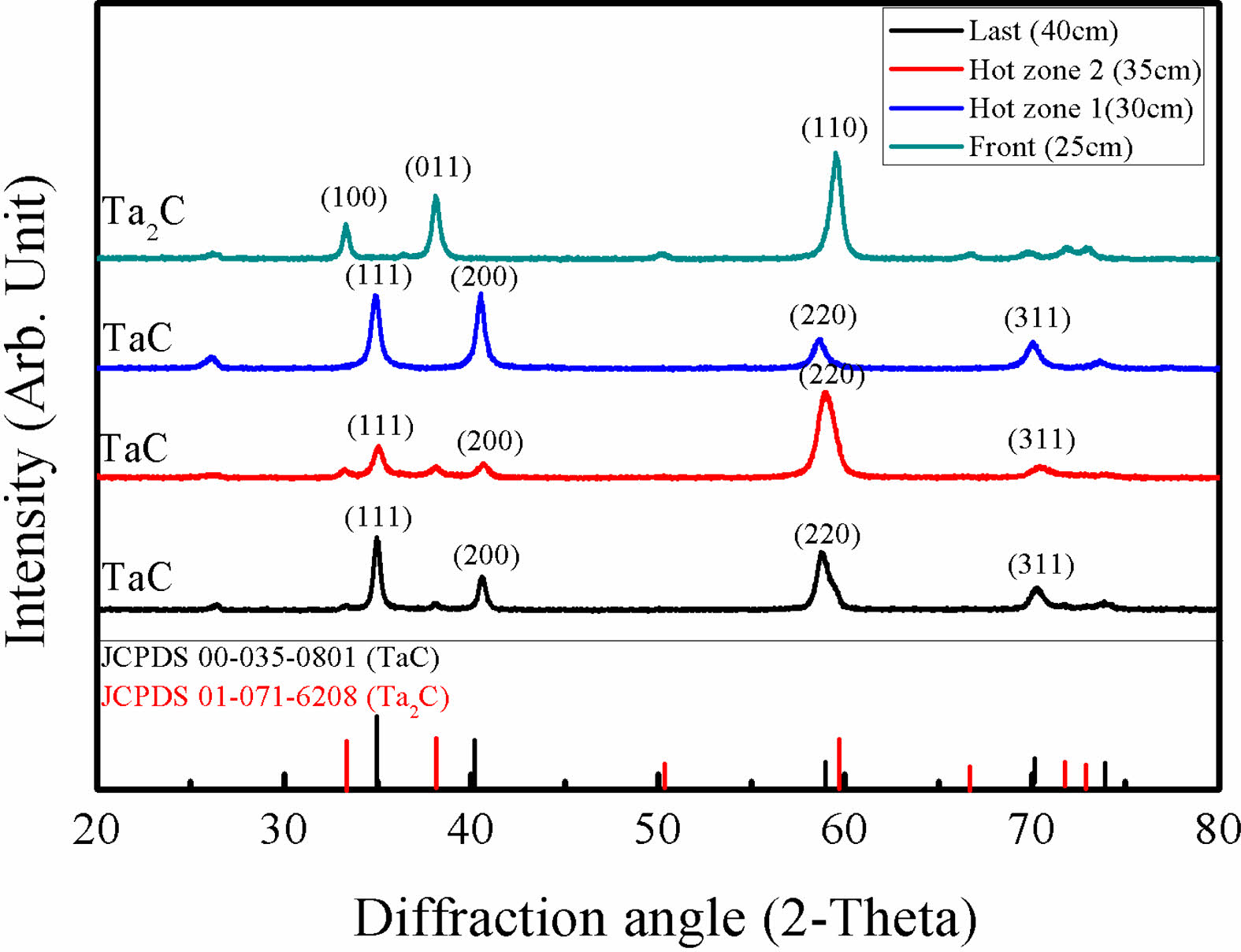
XRD results of different deposition position at 1200 oC are presented in Fig. 3. Specimens in the hot zone area showed TaC phases with different peak intensities. Ta2C phases appeared at the front of the hot zone by the high depletion rate of TaCl5. As the depositions were in process Ta2C phases were changed to TaC. Eventually, unlike other transition metal carbides, for TaCl5, at the end of the deposition area gaseous precursors were depleted. The depletion speed of TaCl5 and the dilution gas amount also affected the microstructure of TaC. Low temperature deposited TaC shows columnar growth at the beginning. However, with the fast depletion rate of TaCl5, columnar structures are covered by wave-like microstructures. In addition, micro pores appeared at the wave-like pattern microstructures by the high amount of dilution gas and the depletion of TaCl5.
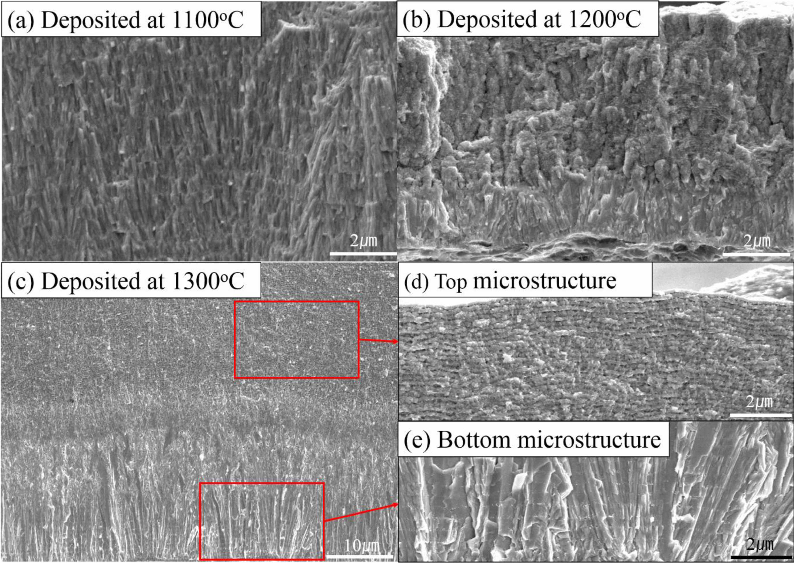
Microstructural analysis of different deposition temperatures are shown at Fig. 4. At 1100 oC and 1200 oC fine columnar growth structures were formed without pores (Fig. 4(a), (b)). However, with the increase of deposition temperature microstructural difference was shown. At the highest deposition temperature, a mixture of columnar and wave-like microstructure was observed (Fig. 4(c)). On the top of the microstructure shows a wave-like microstructures with micro pores (Fig. 4(d)). TaC grains have a columnar microstructure at the bottom of the film, with the sufficient TaCl5 amount (Fig. 4(e)). Microstructural evolution of the film is related with the depletion of the source material. Wave-like microstructures were also observed in other transition metal carbides [30].
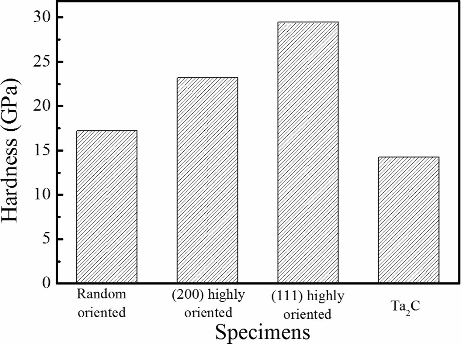
The hardness of deposited TaC film is shown on Fig. 5. Reference specimen deposited at 2100 oC had random orientations. TaC deposited at 1100 ºC were (111) highly oriented and those deposited at 1200 ºC were (200) highly orientation. Ta2C phase specimens which was deposited near the gas inlet was also measured. The average hardness of the TaC material is known to be in the range of 15-19 GPa [7]. Riedl et al. [19] studied the relation of hardness and carbon content. When the carbon amount of TaC is higher than 0.78 and lower than 1.04, the hardness is optimal. The hardness value of the reference, random orientation and Ta2C specimens were similar to the average values that have been reported. On the other hand, the (111) highly oriented specimen had the highest value of 29 GPa; the (200) high orientation specimen showed the second high value of 23 GPa. The hardness value is related with the orientation and stoichiometry of TaC. TaCl5 partial pressure during the deposition process and temperature determines the TaC orientations. When the deposition process is performed on low temperature, the TaCl5 depletion rate is low. However, when the deposition temperature is high. TaCl5 depletion speed is fast and the stoichiometry of TaC films are changed. Also, at low temperature (200) and (220) orientations first appears and these orientations possesses tensile stress during microstructure formation. This orientations determine the hardness value of the film [25].
Microstructural evolution after heat treatment
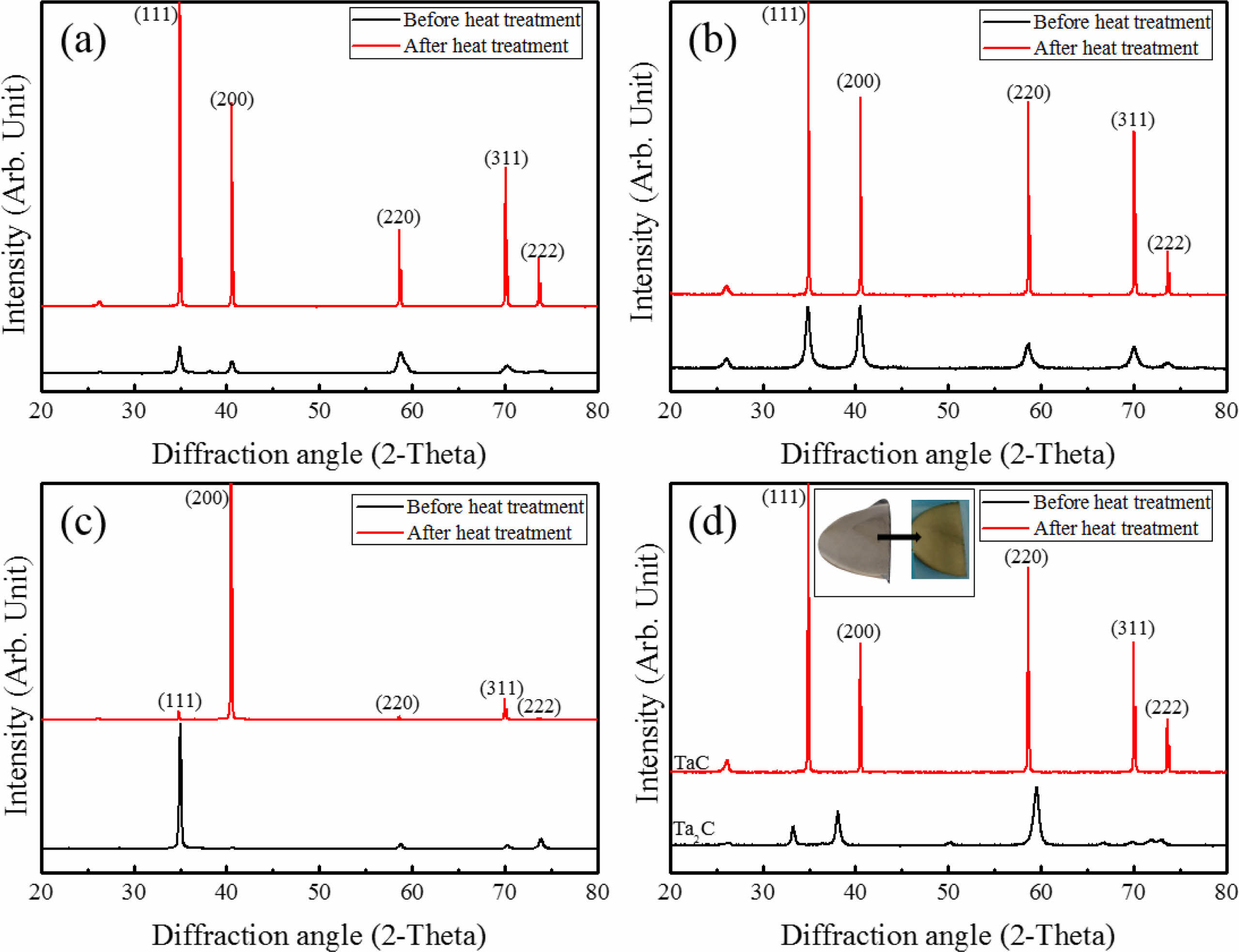
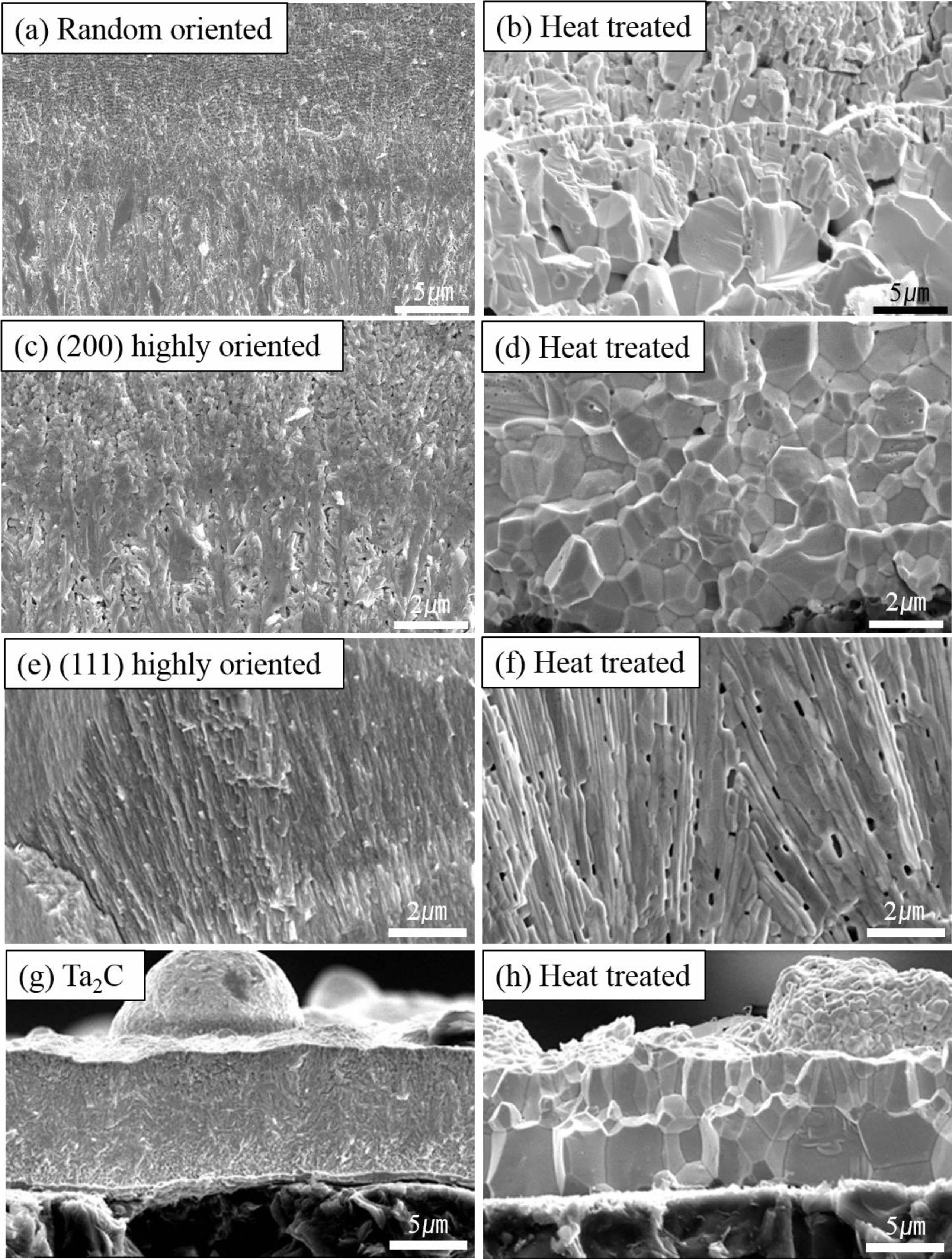
Intensity and orientation change of TaC films during heat treatment were shown on Fig. 6. The crystallinity of TaC was found to be enhanced with the increase of peak intensity and become sharp. This is related with the grain growth during the heat treatment. Randomly oriented TaC showed a significant increase of intensity (Fig. 6(a)). (200) slightly oriented TaC showed intensity change with the increase of (111) orientation (Fig. 6(b)). TaC with (111) highly oriented peaks were changed to (200) (Fig. 6(c)). There were not many changes of the lattice parameters during heat treatment (4.4530 Å to 4.4547 Å). Preferred nucleation growth of films is related with the depletion of the source gas materials. When the nucleation sites are coupled with relatively low reactant concentration nucleation densities are suppressed in specific orientations. However, film orientations could be changed by heat treatment. During the heat treatment, recrystallization and grain growth works on the film microstructure and the grain structures could be change with the pore evolution [33]. Also, Ta2C was changed to TaC random orientation (Fig. 6(d)). In particular, Ta2C specimen before heat treatment showed gray like color. However, the heat treatment result showed the phase change to TaC and color change to gold of Ta2C. During heat treatment, the stoichiometry of Ta2C changed to TaC by atom concentration changes. Microstructural evolution starts due to heat treatment, with recrystallization and grain growth. Slight grain growth was observed on microstructures of all specimens with pore evolution at the grain boundaries of the heat treated specimens except Ta2C. On Ta2C deposition process, TaCl5 was depleted quickly at the early deposition process and excess Ta or excess transition metal participates in forming the microstructure on the bottom at first [34]. The randomly oriented TaC showed a mixture of columnar and wave-like structures before the heat treatment (Fig. 7(a)). Fine columnar growth structures were grown on the early deposition process and wave-like structure was formed. It is also seen in other transition metal carbides with depletion of source material [34]. The heat treatment provided driving force for the grain growth and pore movement. Columnar structures were transformed to equiaxed structures. Wave-like structures showed similar equiaxed grain structures but slight grain growth (Fig. 7(b)). This is related with pore evolution in wave-like structures. TaC with slightly high (200) orientation has similar microstructure with random orientation (Fig. 7(c)). Microstructure of (200) orientation has no wave-like structures. However, after heat treatment microstructural change was shown as the fine grain structure to coarse equiaxed grains (Fig. 7(d)). TaC with (111) orientation deposited at 1100 oC showed fine columnar growth structures without pores before heat treatment (Fig. 7(e)). The micro pore evolutions appeared at the grain boundary without grain growth by heat treatment. In contrast, Ta2C had a dense structure with no pores at the grain boundary before and after heat treatment (Fig. 7(g) and (h)). Only the grain structure was changed to columnar to equiaxed structure. Microstructural evolution of Ta2C to TaC is related with the excess Ta during the early deposition process and formed Ta2C. During the heat treatment, recrystallization and vapor atom movement was occurred and the stoichiometry of Ta2C changed to TaC. However, the dense microstructure was not affected.
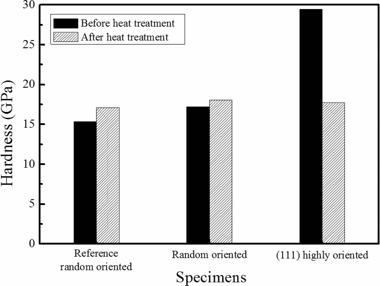
Hardness after heat treatment was compared with those of before (Fig. 8). The commercial reference TaC which was processed above 2100 oC was measured also and the random orientation TaC show average hardness. Heat treatment derived slightly increase of hardness. It was found that (111) highly oriented TaC has the highest hardness value before heat treatment. Hardness decreased and became similar to the average TaC hardness after heat treatment which could be affected by the micropores and orientation changes.
|
Fig. 1 XRD results of TaC with different deposition temperatures. |
|
Fig. 2 Deposition rate of TaC with different positions. |
|
Fig. 3 XRD results of TaC deposited at different positions. |
|
Fig. 4 Microstructure of chemical-vapor deposited at different positions. (a) TaC deposited at 1100 ºC, (b) TaC deposited at 1200 ºC, (c) Microstructure of deposition at 40cm away from gas inlet, (d) top microstructure of (c), (e) bottom microstructure of (c). |
|
Fig. 5 Hardness of TaC specimens with different orientations and phases. |
|
Fig. 6 XRD results before and after heat treatment. (a) TaC with random orientation (b) TaC with (200) slightly high orientation, (c) TaC with (111) high crystal orientation, (d) TaC deposited with Ta2C. |
|
Fig. 7 Microstructures before and after heat treatment. (a) TaC with random orientation, (b) heat treated (a), (c) TaC with (200) slightly high oriented, (d) heat treated (c), (e) TaC with (111) highly oriented, (f) heat treated (e), (g) Ta2C phases, (h) heat treated (g). |
|
Fig. 8 Hardness changes before and after heat treatment. Reference TaC was deposited above 2000 oC. Random oriented TaC was deposited at the middle of the deposition position. (111) highly oriented was deposited at 1100 oC. |
TaC was deposited on a graphite by using TaCl5-C3H6-H2 CVD method. In order to investigate the microstructural stability at elevated temperature, heat treatment was performed for 4 hours at 1850 oC in Ar condition. TaC deposited at lower temperature below 1300 oC showed low crystallinity compared to the reference TaC deposited above 2100 oC. At the high partial pressure of TaCl5, dense and crystalline TaC was deposited. Crystallographic orientation was changed from (111) and (200) to random as deposition temperature increased from 1100 oC to 1300 oC. At 1200 oC, various deposition positions were adopted and orientation, microstructure difference was observed. Heat treatment considerably enhanced the crystallinity of TaC. Especially, Ta2C phases changed to TaC random crystal orientation and (111) highly oriented TaC changed to (200). Also, columnar structures were changed to equiaxed grain structures with grain growth. During the heat treatment, micropores moved to the grain boundary regions and were coalesced into the large pores. As deposited TaC with (111) highly orientation showed a highest value of 29 GPa. The heat treatment process led to a significant crystallographic orientation change and the effect of (111) highly oriented TaC was disappeared. The hardness value decreased as same as the reference value because of the formation of micropores.
This work was supported by a National Research Foundation of Korea (NRF) grant funded by the Korean Government (MSIP) (No. 2017M2A8A4017642).
- 1. N.P. Padture, Nat. Mater. 15 (2016) 804-809.
-

- 2. E.L. Corral, R.E. Loehman, J. Am. Ceram. Soc. 91 (2008) 1495-1502.
-

- 3. C.R. Wang, J.-M. Yang, W. Hoffman, Mater. Chem. Phys. 74 (2002) 272-281.
-

- 4. E. Wuchina, E. Opila, M. Opeka, W. Fahrenholtz, I. Talmy, Electrochem. Soc. Interface 16 (2007) 30-36.
-

- 5. W.G. Fahrenholtz, G.E. Hilmas, Scripta Mater. 129 (2017) 94-99.
-

- 6. H.O. Pierson, in “Handbook of Chemical Vapor Deposition (CVD)” (Noyes Publications, 1999) p.223-225.
-

- 7. G.B. Thompson, C.R. Weinberger, in “Ultra-High Temperature Ceramics: Materials for Extreme Environment Applications” (John Wiley & Sons, 2014) p.291-315.
-

- 8. I.T. Martin, C.W. Teplin, P. Stradins, M. Landry, M. Shub, R.C. Reedy, B. To, J.V. Portugal, J.T. Mariner, Thin Solid Films 519 (2011) 4585-4588.
-

- 9. D. Nakamura, T. Kimura, T. Narita, A. Suzumura, T. Kimoto, K. Nakashima, J. Cryst. Growth 478 (2017) 163-173.
-

- 10. R.A. Morris, B. Wang, L.E. Matson, G.B. Thompson, Acta Mater. 60 (2012) 139-148.
-

- 11. X. Zhang, G.E. Hilmas, W.G. Fahrenholtz, J. Am. Ceram. Soc. 90 (2007) 393-401.
-

- 12. Z.J. Dong, X.K. Li, G.M. Yuan, Y. Cong, N. Li, Z.J. Hu, Z.Y. Jiang, A. Westwood, Appl. Surf. Sci. 254 (2008) 5936-5940.
-

- 13. L. Liu, F. Ye, Y. Zhou, Mater. Sci. Eng. A 528 (2011) 4710-4714.
-

- 14. M. Ali, M. Ürgen, M.A. Atta, Surf. Coat. Tech. 206 (2012) 2833-2838.
-

- 15. G. Hakansson, I. Petrov, J.-E. Sundgren, J. Vac. Sci. Technol. A 8 (1990) 3769-3778.
-

- 16. K. Balani, G. Gonzalez, A. Agarwal, R. Hickman, J. Scott O'Dell, S. Seal, J. Am. Ceram. Soc. 89 (2006) 1419-1425.
-

- 17. Y.-H. Chang, J.-B. Wu, P.-J. Chang, H.-T. Chiu, J. Mater. Chem. 13 (2003) 365-369.
-

- 18. H. Riedl, T. Glechner, T. Wojcik, N. Koutná, S. Kolozsvári, V. Paneta, D. Holec, D. Primetzhofer, P.H. Mayrhofer, Scripta Mater. 149 (2018) 150-154.
-

- 19. R. Teghil, L.D. Alessio, G. De Maria, D. Ferro, Appl. Surf. Sci. 86 (1995) 190-195.
-

- 20. L. Massot, P. Chamelot, P. Taxil, J. Alloys Compd. 424 (2006) 199-203.
-

- 21. Z.-K. Chen, X. Xiong, Mater. Chem. Phys. 141 (2013) 613-619.
-

- 22. X. Xiong, Z.-K. Chen, B.-Y. Huang, G.-D. Li, F. Zheng, P. Xiao, H.-bo Zhang, Thin Solid Films 517 (2009) 3235-3239.
-

- 23. Z.-K. Chen, X. Xiong, G.-D. Li, W. Sun, Y. Long, Appl. Surf. Sci. 257 (2010) 656-661.
-

- 24. G.-D. Li, X. Xiong, K.-L. Huang, Trans. Nonferrous Met. Soc. China 19 (2009) 689-695.
-

- 25. Z.-K. Chen, X. Xiong, Y. Long, Appl. Surf. Sci. 257 (2011) 4044-4050.
-

- 26. D. Kim, S.M. Jeong, S.G. Yoon, C.H. Woo, J.I. Kim, H.-G. Lee, J.Y. Park, W.-J. Kim, J. Kor. Ceram. Soc. 53 (2016) 597-603.
-

- 27. D.N. Lee, in “Texture and Related Phenomena” (Hanrimwon Publishing Company, 2006) p.217-225.
- 28. D.N. Lee, H.N. Han, Mater. Sci. Eng. 82 (2015) 1-4.
-

- 29. D.N. Lee, J. Mat. Sci. 34 (1999) 2575-2582.
-

- 30. A.I. Gusev, A.S. Kurlov, V.N. Lipatnikov, J. Solid State Chem. 180 (2007) 3234-3246.
-

- 31. Y. Gong, R. Tu, T. Goto, Mater. Trans. 50 (2009) 2028-2034.
-

- 32. M. Patterson, Oxidation Resistant HfC-TaC Rocket Thruster for High Performance Propellants, NASA Report No. NAS3-27272 (1999).
- 33. J. Pelleg, L.Z. Zevin, S. Lungo, Thin Solid Films 197 (1991) 117-128.
-

- 34. D. Kim, Y.B. Chun, M.J. Ko, H.-G. Lee, M.-S. Cho, J.Y. Park, W.-J. Kim, J. Nucl. Mater. 479 (2016) 93-99.
-

 This Article
-
2022; 23(6): 751-757
Published on Dec 31, 2022
- 10.36410/jcpr.2022.23.6.751
- Received on Dec 4, 2019
- Revised on Mar 23, 2020
- Accepted on Mar 24, 2020
 Services
- Abstract
introduction
experimental procedure
results and discussion
conclusions
- Acknowledgements
- References
- Full Text PDF
Shared
 Correspondence to
- Daejong Kim
-
Nuclear Materials Development Division, Korea Atomic Energy Research Institute, Daejeon 34057, Republic of Korea
Tel : +82-42-868-4559 Fax: +82-42-868-8549 - E-mail: dkim@kaeri.re.kr


 Copyright 2019 International Orgranization for Ceramic Processing. All rights reserved.