- Microstructural analysis and optimization of welding parameters for AA1100 welded plates
Thirumalai Ra,*, Karthick Sb and Giriraj Mc
aProfessor, Mechanical Engineering, Dr.N.G.P. Institute of Technology, Coimbatore, India
bAsst.Professor, Mechanical Engineering, AVS College of Technology, Salem, India.
cAssociate Professor, School of Mechanical Engineering, VIT University, Vellore, IndiaThis article is an open access article distributed under the terms of the Creative Commons Attribution Non-Commercial License (http://creativecommons.org/licenses/by-nc/4.0) which permits unrestricted non-commercial use, distribution, and reproduction in any medium, provided the original work is properly cited.
Friction stir welding (FSW) process is used in this research work to optimize the welding process parameters of welding of AA1100 aluminium alloy. Taguchi grey relational analysis is used for optimization of the process parameters. The welding process parameters considered in this research work are tool rotational speed, feed and axial load against the responses hardness, tensile strength at room and elevated temperature and % elongation at room and elevated temperature. L27 orthogonal array is used to conduct the experiments and the impact of the process parameters on the responses are analyzed and presented. The characterization of the weld is analyzed and it is seen that the fine dimples projects ductile fracture and the cracks present on flat surface exhibits brittle fracture
Keywords: Aluminium Alloy, AA1100, Hardness, Tensile strength, Tool rotational speed
Aluminium alloy AA1100 has been predominantly used in several fields of engineering because of its excellent mechanical properties [1]. Aluminium alloys are welded with several welding techniques such as Laser welding, metal arc welding, Gas Tungsten Arc Welding and so on [2-4]. However solid state welding technology such as vacuum diffusion [5] and FSW are becoming familiar to join aluminium alloys. Previously researchers thought the complexity in solid state welding will leads to high distortion, development of residual stresses, solidification cracking, and brittle phases during welding [6, 7]. This gives a new development to the invention of Friction stir welding by Thomas at The Welding Institute (TWI), United Kingdom, in 1991 [8]. FSW eliminates all welding defects encountered in solid state welding techniques and provided excellent welding characteristics. The geometry of the welding tool, tool rotational speed, tool offset, axial load, welding feed are some of the significant welding process parameters used by the researchers in experimental investigations of the FSW joints. [9]. A permanent joint is obtained once the plasticized material forms over the heat affected zone because of the frictional heat created over the work piece [10]. Friction takes place between rapidly rotating probe (or tool pin) and material to be welded when its brought into contact heat will produced by friction which weld the two materials or metals, sheets etc.., i.e., welding by using friction. No external heat is applied in this process. It is not a fusion welding, which where the resultant joint is stronger than parent material. The schematic of FSW is presented in Fig. 1. To process a plate by friction stir, a cylindrical tool with hexagonal probe with large diameter shoulder is specially designed, which is plunged into selected area while rotating. The rotating pin is get into contact with surface, when plunged into selected area of the plate. The friction between the plate surfaces, the shoulder quickly heats and softens the small column of metal, which enables tool to reach the surface of the. The shoulder of the tool and the probe length is used for controlling the penetration depth. During this process, the processed zone rea and the tool will move relative to each other, until desired grain size is processed in selected area. As the tool passes, the processed zone cools and it forms defect free, dynamically recrystallized and equalized fine grained microstructure. The several process parameters involved in FSW are tool design, tool rotational speed, axial force etc. The tool is made by through hardening with hexagonal design to improve the weld quality and maximum welding speed. The material of the tool is H13 which is adequately solid, intense and hard wearing, at welding temperature. When the rotational speed of tool increases or decreases, weld quality is also increased or decreased respectively. The axial force increases as the thickness of the welding plate increases. The butt and lap joints are mostly suitable for FSW. Two plates (or sheets) with same thickness are need to be clamped firmly on a backing plate to prevent faces of joints being forced apart. Butt or lap joints of the metal plates could be easily combined together without any concern about surface condition of plates. In this study FSW of AA1100 is welded together successfully. The joints design and a fixture arrangement is necessary to provide sufficient area weld pool and to provide enough push to prevent movement of work pieces, and heat sink to remove the heat of welding. The requisite area of the welding tool shoulder is function of alloy material and its thickness. For Aluminum alloys, the tool pin requires thickness about 3 or 5 times the material thickness. Smaller diameter shoulder could be used for lower thermal conductivity materials. FSW provides several benefits such as; no fumes or spans are generated, so no need of shielding gas, a non-consumable tool is used, due to less amount of temperature involved, shrinkage during solidification is less and so on. The limitations of FSW are welding speeds is moderately slower and at end of each weld there is a keyhole, when thickness of the material varies, the tool pin with different geometry is required and so on. The mechanism and process parameters of the FSW process are crucial to understand while heat transfer during modeling [11] and they developed and analysed a less meshing particle for transient heat transfer while FSW process. The lap joint between aluminium and nickel based alloys in FSW is investigated [12]. The effect on microstructure and mechanical properties due to depth of plunge into the welding alloys are studied and anlysed. The parameters for joining aluminium based alloys by FSW are investigated and the mechanical and metallurgical test on test specimen under room temperature are analysed [13]. Dissimilar material is placed between the aluminium alloys and welded together by FSW are investigated for its effec- tiveness [14]. The mechanical properties are analysed as per the process parameters after the FSW. The FSW for dissimilar metals AA6082 and AA5754 are inves- tigated [15] and optimization is carried out using Taguchi Analysis. To investigate the welding properties of AA1100 alloys, they are welded by varying the significant welding process parameters. The shoulder diameter and the pin diameter of the tool is considered as the parameter for investigating the welding strength, hardness, and corrosion rate [16]. Orthogonal array is used to conduct 27 experiments and grey relational analysis is used for multi objective optimization and selection of optimum drilling parameters [17]. The importance of tungsten carbide based tool pin on the microstructure and mechanical properties of AA1100 FSW process is investigated [18]. The tool pins used in FSW plays an important role in the investigations of welding parameters [19].
Process parameters of electric resistance spot welded dissimilar weldments are analysed [20]. The mechanical and metallurgical behavior in friction stir welding of AA5052-H32 and AA5083-H111 aluminium alloys are investigated [21].
|
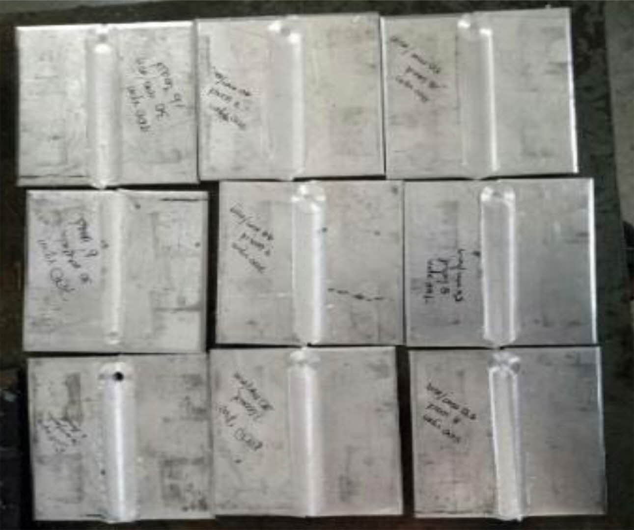
Fig. 1 Friction stir welded specimens of AA1100 aluminium alloy. |
AA1100 aluminum alloy sheets were selected for experimental analysis. Friction stir welded specimens of AA1100 aluminium alloy are presented in Fig. 1. The thickness of the AA1100 plate used in this research work is 5 mm and the length of the plate is 300mm and width of the plate is 150 mm in dimensions. The flattened round tool pin is used in this research work with shoulder diameter 20 mm and tool pin diameter 5mm. When the tool shoulder is of smaller in diameter, the heat is generated effectively and more uniformly. Clamps made up of high carbon steel are used for clamping the work pieces rigidly during the FSW process. Single pass friction stir weld is employed for the AA1100 plates and weld is obtained and anlaysed for its tensile strength and hardness. Computer controlled FSW machine is used for this purpose and the speed of this machine is 4000 rpm with power 22 kW. The tensile strength is performed in a 100 kN servo controlled universal testing machine along the transversal direction along the line of the weld. The ASTM standard E8M is followed during the tensile testing of the welding specimen. Tensile strength is measured for the specimen maintained at room temperature and at elevated temperature. Three readings are recorded for each experimental value and the average of these three values are reported here in this work. Vicker micro hardness testing machine is used for measuring the hardness of the weld nugget zone with 15 sec dwell time with 0.05 kg load.
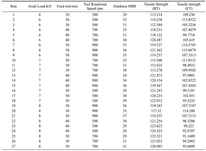
In this work axial load, tool rotational speed and feed are selected as the process parameters and the hardness and tensile strength at room and elevated temperatures are considered as the responses. L27 orthogonal array is used and nine experiments are conducted and the responses are recorded against each experiment. The Taguchi grey relational analysis is used to optimize the welding process parameters. The responses considered in this work are; hardness, tensile strength at room and elevated temperatures. Rockwell hardness is measured and recorded and tensile test are carried out as per ASTM standards and recorded. The metallographic study is considered to examine the heat affected zone, thermo-mechanically affected zone and stir zone generated during FSW process. The experimental data is presented in Table 1.
The base metal is kept perpendicular to the weld direction. M-43 grade non- consumable electrodes made of high carbon steels are used in this work for welding purpose. The geometry of the tool is a rectangular pin with round shoulder of height 5.8 mm is used here for FSW process. Micro structural analysis of the weldment is carried out using optical microscope. The tensile test is examined for the fractured surfaces by scanning electron microscope (SEM).
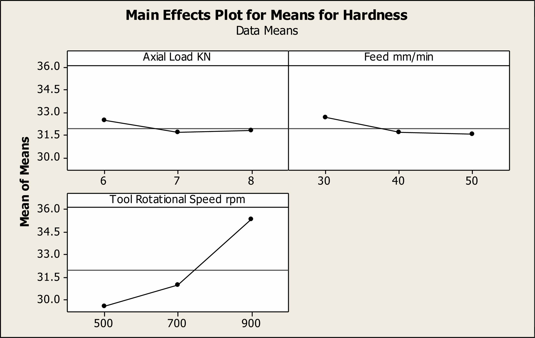
The increase in tool rotational speed will increase the hardness. Maximum hardness is recorded at 900 rpm and minimum hardness is recorded at 500 rpm. The value of hardness is observed between the ranges of 25 HRB to 35 HRB for the FSW AA1100 alloys for all input parameters. When the rotational speed is high, the tensile strength is found to be high. During this stage the heat generation is high due to the principle of friction and this high heat generated will touch the tool shoulder and surfaces of the plate effectively. Better plasticization is observed when the tool rotational speed is high and better tensile strength is also observed, whereas low rotational speed produces poor tensile strength and inadequate plasticization of the material. Due to high rotational speed, turbulence effect is pro- duced in the heat affected zone and thereby effective welding of the material in fused state is obtained. Because of this, uniform flow of metal is created and hence the tensile strength is improved. Turbulent flow is witnessed when the rotational speed is low and this creates poor fusion of the materials and ultimately results in failure of the weld. The tensile strength is recorded in the ranges of 90-100 Mpa and the aial force is recorded in the range of 90 -120 Mpa. Also the tensile strength of the specimen at elevated temperature of 200 degree Celsius is recorded and it is concluded that the tensile strength of the specimen at the elevated temperatures are low when compared to the tensile strength of the specimen at room temperatures. This is because of the increase in ductility of the material at the elevated temperatures. The axial force decreases linearly with increase in tensile strength.
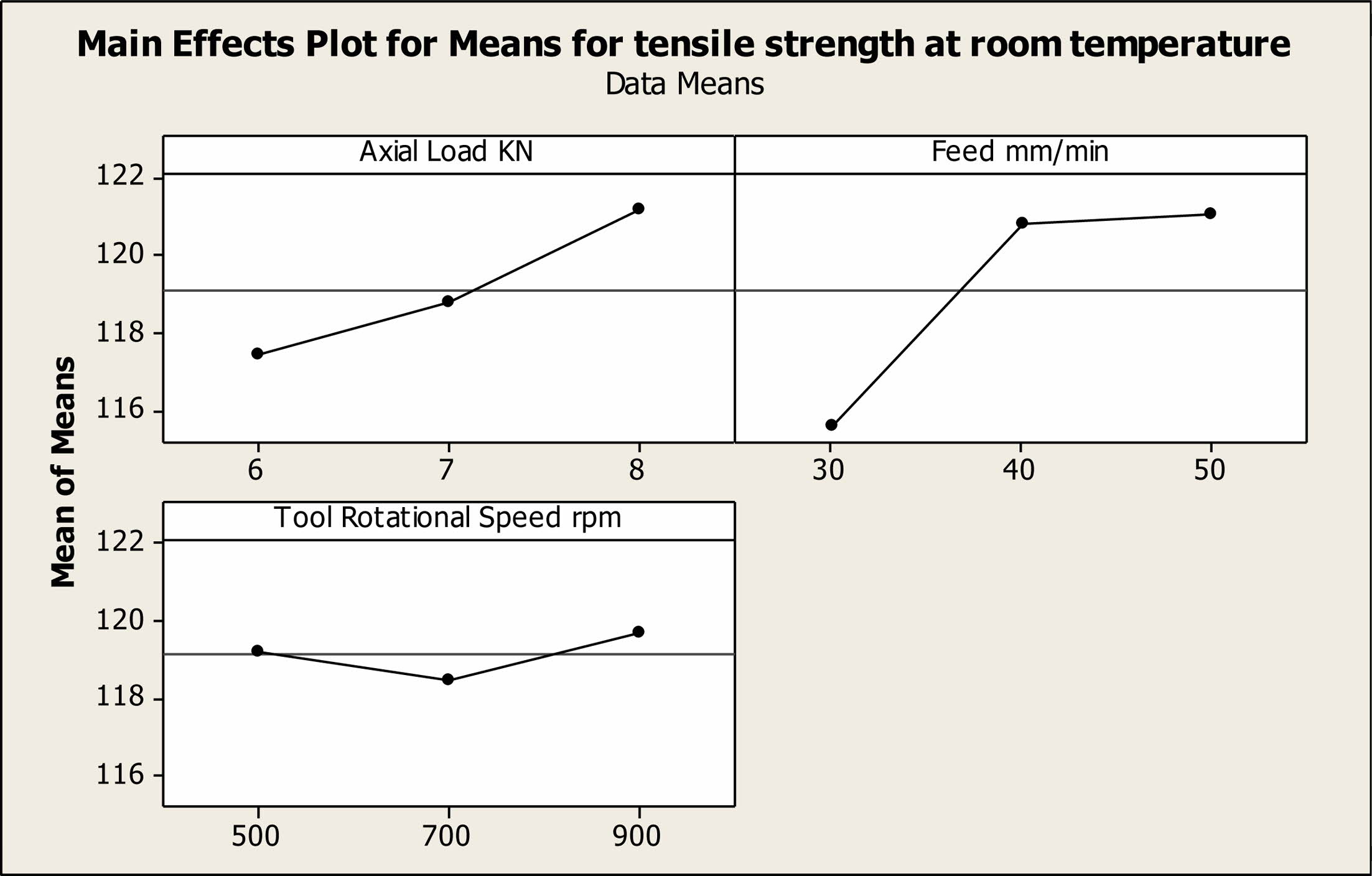
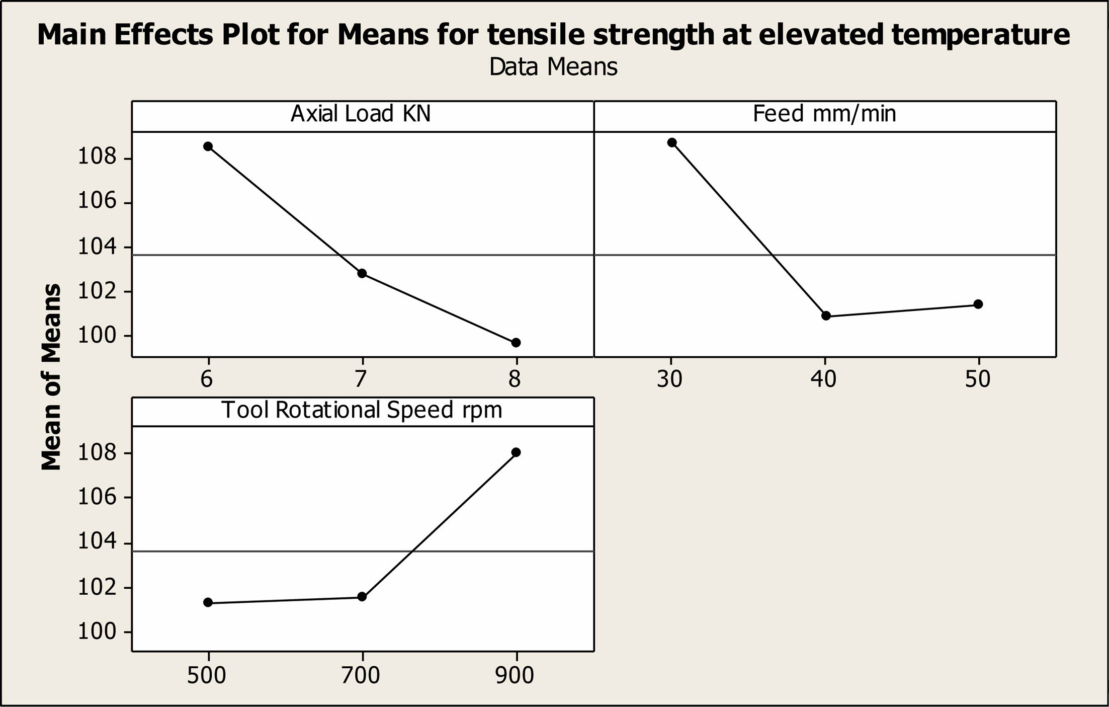
Analysis of variance is useful in determining the most significant and predominant factor affecting the process parameters during FSW of AA1100 Aluminium alloy. The level of significance is carried out 5% signi- ficance level. Table 2. shows the results of analysis of variance for hardness (ANOVA) for welding AA1100 using FSW process. It is observed that the tool rotational speed plays a predominant role and it is the most significant in determining the hardness of the welded specimen. The next significant parameter is feed and it is followed by the axial load. Table 3. shows the results of analysis of variance for tensile strength at room temperature (ANOVA) for welding AA1100 using FSW process. It is observed that the feed plays a pre- dominant role and it is the most significant in deter- mining the hardness of the welded specimen. The next significant parameter is axial load and it is followed by the tool rotational speed. Table 4. shows the results of analysis of variance for tensile strength at elevated tem- perature (ANOVA) for welding AA1100 using FSW process. It is observed that the feed and axial plays a predominant role and it is the most significant in deter- mining the hardness of the welded specimen. Taguchi analysis is carried out using Design of experts and the main effects plots for means for hardness are presented in Fig. 2. It is observed that as the tool rotational speed is increased the hardness of the welded specimen also increases linearly. Whereas the increase in axial load and feed of the FSW process shows a minimum change in variation of the hardness of the welded specimen. The main effects plots for means for tensile strength at room temperature are presented in Fig. 3. It is observed that as the feed rate and axial load is increased the tensile strength at room temperature of the welded specimen also increases linearly. The main effects plots for means for tensile strength at elevated temperature are presented in Fig. 4. It is observed that as the axial load is decreased the tensile strength at the elevated temperature of the welded specimen also increases linearly. From the mean effects plots for the tensile strength at the room temperature and elevated tempera- tures, it is concluded that the tensile strength of the specimen increases with increase in tool rotational speed due to high amount of friction generated at the tool shoulder and tool pin. Due to this high heat generation the material flow is enhanced and creating a uniform coalescence of the weld in the welding zone. When the tool rotation speed is low, the uniformity of the heat generation is highly affected thereby producing porosities in the weld zone there by reducing the tensile strength of the specimen. Also it is concluded that the hardness of the weld zone increases to a very minimum proportion when compared to the parent material due to improvement in the grain size of the stir zone during the FSW process is facilitated.
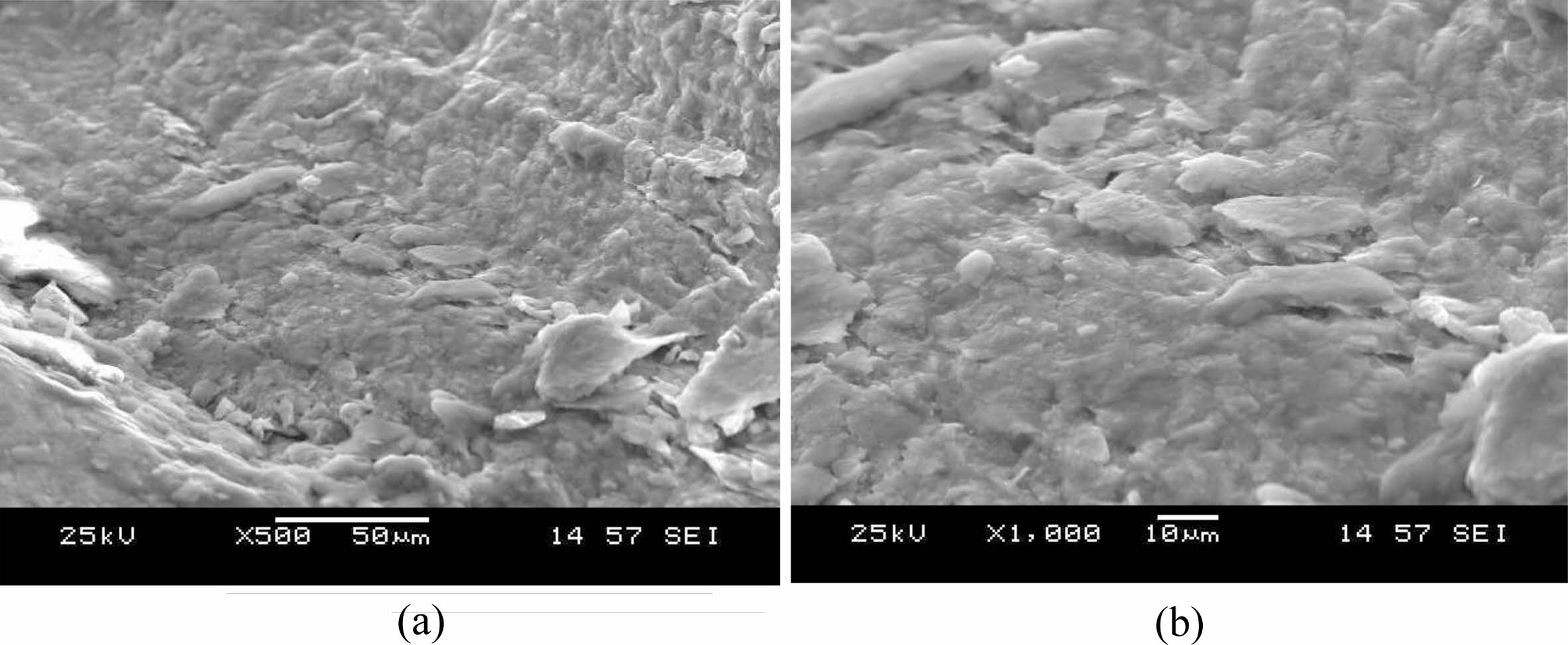
Fig. 5 show the Scanning Electron Micrograph of fractured surface. The fine dimples produce the ductile fracture and it is treated to be as a predominant failure of the weld. The small dimples are found to be originated from the grains at the failure location. The tiny dimples with primary fracture are seen and it represents an initiation of crack on the surfaces of the material which reveals the formation of the brittle fracture. Brittle fracture regions initiate’s micro cracks and large dimples are also found in some parts of the fracture areas. Because of this a bigger plastic deformation, dimples areas are observed as cracks in the fracture zone.
|
Fig. 2 Main effect plot for means for hardness. |
|
Fig. 3 Main effect plot for means for tensile strength at room temperature |
|
Fig. 4 Main effect plot for means for Tensile strength at elevated temperature |
|
Fig. 5 SEM analysis - Microstructure of AA1100 welded joints by FSW: (a) 500x and (b) 1000x. |
|
Table 4 Analysis of Variance Table for Tensile strength at Elevated Temperature. |

Grey relational analysis is used in this work to optimize the process parameters of AA1100 alloy sheet metals welded by FSW process. The hardness and tensile strength are selected as the responses against the process parameters tool rotational speed, axil force and feed rate. The SEM micrograph clearly explains the sequence of ductile fracture with the presence of fine dimples exhibits ductile fracture. The GRA confirms that the axial load is the predominant factor in optimization of FSW process and it is followed by tool rotational speed and feed rate.
- 1. M. Raei, M.R. Toroghinejad, and R. Jamaati, Mater. Manuf. Processes. 26[11] (2011) 1352-1356.
-

- 2. B.T. Gibson, D.H. Lammlein, T.J. Prater, W.R. Longhurst, C.D. Cox, M.C. Ballun, K.J. Dharmaraj, G.E. Cook, and A.M. Strauss, J. Manuf. Processes. 16[1] (2014) 56-73.
-

- 3. Y. Liu, W. Wenjing, X. Jijia, S. Shouguang, W. Lian, Q. Ye, M. Yuan, and W. Yujie, Mater. Sci. Eng. A 547 (2012) 07-13.
- 4. L.M. Zhao and Z.D. Zhang, Scr. Mater. 58[4] (2008) 283-286.
-

- 5. K. Dheenadayalan, S. Rajakumar, and V. Balasubramanian, Appl. Mech. Mater. 787 (2015) 495-499.
-

- 6. P. Kah, R. Rajan, J. Martikainen, and R. Suoranta, Int. J. Mech. Mat. Eng. 10[1] (2015) 26-35.
-

- 7. A.F. Norman, K. Hyde, F. Costello, S. Thompson, S. Birley, and P.B. Prangnell, Mater. Sci. Eng. A 354[1-2] (2003) 188 - 198.
-

- 8. H. Li, J. Gao, Q. Li, A. Galloway, and A. Toumpis, Sci. Technol. Weld. Joining. 24[2] (2009) 156-162.
-

- 9. R. Kumar, B. Bora, S. Chattopadhyaya, G. Krolczyk, and S. Hloch, Int. J. Mater. Prod. Technol. 57[1-3] (2018) 204-229.
-

- 10. W. Xunhong and W. Kuaishe, Mater. Sci. Eng. A 431[1-2] (2006) 114-117.
-

- 11. R. Palanivel, P. Koshy Mathew,s and N. Murugan, J. Eng. Sci. Technol. Rev. 4[1] (2011) 25-31.
-

- 12. Q. Zheng, X. Feng, Y. Shen, G. Huang, and P. Zhao, J. Alloys Compd. 695 (2016) 952-961.
-

- 13. P.M.G.P. Moreira, T. Santos, S.M.O. Tavares, V. Richter-Trummer, P. Vilaça, and P.M.S.T. De Castro, Mater. Des. 30[1] (2009) 180-187.
-

- 14. S. Ravikumar, V. Sesshagiri Rao, and R.V. Pranesh, J. Adv. Mech. Eng. 4 (2104) 101-114.
- 15. S. Kasman, Int. J. Adv. Manuf. Technol. 68[1-4] (2013) 795-804.
-

- 16. S. Rajakumar and V. Balasubramanian, J. Mater. Eng. Perform. 21[6] (2012) 809-822.
-

- 17. M. Srinivasan, S. Ramesh, S. Sundaram, and R. Viswanathan, J. Ceram. Process. Res. 22[3] (2021) 345-355.
-

- 18. A. Tamadon, A. Baghestani, M.E. Bajgholi, Technologies. 8[2] (2020) 34.
-

- 19. R.V. Vignesh and R. Padmanaban, Mater. Today: Proc. 5[8] (2018) 16716-16723.
-

- 20. M. Kannaiyan, J.G. Raghuvaran, K.Govindan, and E.P. Annamalai. J. Ceram. Process. Res. 21[1] (2020) 26-34.
-

- 21. R. Crushan and P. Ashoka Varthanan. J. Ceram. Process. Res. 22[6] (2021) 620-628.
-

 This Article
-
2022; 23(2): 221-227
Published on Apr 30, 2022
- 10.36410/jcpr.2022.23.2.221
- Received on Dec 1, 2021
- Revised on Dec 27, 2021
- Accepted on Jan 10, 2022
 Services
Shared
 Correspondence to
- Thirumalai R
-
aProfessor, Mechanical Engineering, Dr.N.G.P. Institute of Technology, Coimbatore, India
bAsst.Professor, Mechanical Engineering, AVS College of Technology, Salem, India.
cAssociate Professor, School of Mechanical Engineering, VIT University, Vellore, India
Tel : +91 9843240635 - E-mail: vkrthirumalai@gmail.com




 Copyright 2019 International Orgranization for Ceramic Processing. All rights reserved.