- Quenching process effects on the performance of a TiO2 photoelectrode for dye-sensitized solar cells
Woon-Yong Parka and Ki-Tae Leea,b,c,*
aDivision of Advanced Materials Engineering, Jeonbuk National University, Jeonbuk 54896, Republic of Korea
bDepartment of Energy Storage/Conversion Engineering of Graduate School (BK21 FOUR), Jeonbuk National University, Jeonbuk 54896, Republic of Korea
cHydrogen and Fuel Cell Research Center, Jeonbuk National University, Jeonbuk 54896, Republic of KoreaThis article is an open access article distributed under the terms of the Creative Commons Attribution Non-Commercial License (http://creativecommons.org/licenses/by-nc/4.0) which permits unrestricted non-commercial use, distribution, and reproduction in any medium, provided the original work is properly cited.
A rapid cooling (quenching) step has been introduced in fabrication of TiO2 photoelectrodes for dye-sensitized solar cells (DSSCs). The quenching process, studied at a fixed sintering temperature, decreased particle size but increased surface roughness without any substantial change in the crystal structure or oxidation state of TiO2 films. Therefore, the change in the DSSC performance induced by the quenching was related closely to the microstructural and morphological changes in the TiO2 films. Smaller particle size and the rough surface of TiO2 films facilitated dye adsorption and increased the number of active reaction sites. In particular, the enlarged number of active reaction sites produced by the quenching process promoted the charge transfer reaction at the TiO2-dye-electrolyte interface, resulting in overall performance improvement of DSSCs. The conversion efficiency of the furnace cooled- and quenched-TiO2 films at 500 oC were 4.588% and 5.797%, respectively
Keywords: Dye-sensitized solar cells, Photoelectrode, TiO2, Sintering process, Quenching method
Dye-sensitized solar cells (DSSCs) are a promising technological advancement due to their conversion efficiency, low-cost fabrication process, and diverse applicability compared to conventional silicon-based solar cells [1-3]. The structure of a DSSC is composed of photoelectrode, dye sensitizer, electrolyte, counter electrode, and transparent conducting substrate. Electrons are generated by excited-dye molecules adsorbed on the surface of the photoelectrode with incident light and move toward the photoelectrode or electrolyte [4-7]. Various efforts such as electrode surface morphology control [8-12], dopants in the electrode [13-15], develop- ment of advanced dyes [16-18], and electrolytes [19, 20] have aimed to improve the performance of DSSCs.
The photoelectrode in a DSSC plays a key role in enhancing the diffusion of electrons and adsorbing a large number of dye molecules at the electrode surfaces [21-23]. Therefore, the photoelectrode layer usually is fabricated in the form of a mesoporous film with a large surface area to promote efficient light harvesting and a large amount of photo-generation [24]. Meanwhile, TiO2 is one of the most suitable materials to satisfy photoelectrode conditions in DSSCs because of its large band gap (anatase: 3.2 eV, rutile: 3.0 eV), suitable band edge levels for charge injection/extraction, non-toxicity, and low cost [25-28].
Generally, it is advantageous to reduce the particle size of TiO2 in the photoelectrode because more dye molecules can be adsorbed at the extended surface area [7]. However, the reduction of particle size leads to an increase in defects at the boundary [29, 30]. Cao et al. reported that particle size and surface area in the mesoporous films strongly affect electron-hole generation and charge transport from dye to TiO2 particles in the photoelectrode [31, 32]. Yanagida et al. reported that particle size and surface area of TiO2 are major factors that affect the electron diffusion coefficient and recom- bination lifetime [33, 34]. Yang et al. reported that particles with a hollow hemisphere structure can increase the amount of dye adsorption and electron collection efficiency by inducing the light scattering [35]. Meanwhile, the dispersed micro/nano-sized noble metal particles (Au, Ag etc.) in metal oxide nano- particles can improve the performance of DSSCs by plasmonic resonance effect of electrons on the material surface with respect to incident light [36-38]. In this regard, it is important to control the microstructure, such as particle size and surface morphology, of TiO2 photoelectrode to improve the performance of DSSCs. The microstructure can be controlled by manufacture process such as deposition methods for the fabrication of mesoporous films (doctor blading, screen printing, spin coating, etc.), sintering process (temperature, holding time, heating/cooling rate). It is known that the rapid cooling (quenching) process can maintain high temperature phase even at room temperature and suppress the grain growth [39-41]. Especially, it has been reported that TiO2 photoelectrode with small grain size showed much better DSSC performance than that with large grain size [42-45].
In this work, we introduced a rapid cooling (quen- ching) step into the conventional sintering process to modify the microstructure and surface morphology of the TiO2 photoelectrode. The quenching process at various temperatures was conducted to investigate the changes in microstructure and surface morphology. The correlation between performance and change in the microstructure driven by the quenching process was investigated. Unlike the conventional sintering process, the quenching treatment in the sintering process increased the surface area of TiO2 and yielded a larger number of adsorption sites during dye infiltration, resulting in performance improvement of the DSSCs.
Preparation of TiO2 photoelectrode
Fluorine-doped tin oxide (FTO)-coated glass (TEC 8, Pilkington, UK) with a sheet resistance of 6-9 Ω/□ was cleaned using acetone (99.5%, Daejung Chemicals and Metals Co., Korea), 2-propanol (99+%, Alfa Aesar, USA), and DI-water for an interval of 10 min per solvent and then dried using an air gun. A screen printing method was used with TiO2 paste (Ti-Nanoixde T/SP, Solaronix, Switzerland) for deposition of mesoporous TiO2 films. The screen-printed samples were sintered at 500 oC for 30 min in a tube furnace in an ambient atmosphere as shown in Fig. 1. The heating rate was adjusted by 10 oC/min. In conventional cooled (named to “furnace cooled”), The furnace was set to drop from 500 oC to room temperature in 3 hours. Unlike the conventional furnace cooling step, in the quenching step, the sliding furnace was pushed to expose to room temperature atmosphere after finishing the sintering step. The final thickness of TiO2 films was approximately 9 μm. Meanwhile, the sintering temperature was varied at 400, 450, and 500 oC to investigate the sintering tem- perature effect.
Fabrication of DSSCs
The prepared mesoporous TiO2 films were immersed in a prepared 0.3 mM (bis(tetrabutylammonium)-cis-di(thiocyanato)-N,N’–bis(4-carboxylato-4’-carboxylic acid-2,2-bipyridine) ruthenium (Ⅱ) (N719, Solaronix, Switzerland) ethanol-based solution in a dark field at room temperature for 24 h. For the counter electrode, Pt was deposited on indium-doped tin oxide (ITO)-coated glass (STN 10, UID, Korea) with a sheet re- sistance of 6-9 Ω/□ using DC sputtering equipment (E-1030, Hitachi, Japan) at 25 mA for 30 s. The thickness of the deposited Pt was approximately 5 nm.
The DSSC cells were assembled by attaching the photoelectrode and the counter electrode such that they faced one another. A 60-μm-thick Surlyn film (Solaronix, Switzerland) was used as a sealant. An electrolyte with an iodide/tri-iodide (I−/I3−) redox couple in acetonitrile solvent (AN-50, Solaronix, Switzerland) was injected through the holes on the counter electrode. The active area of the TiO2 photoelectrode and electrolyte was 0.25 cm2 and 1.2 cm2, respectively.
Characterization and performance evaluation
X-ray diffraction (XRD) was carried out using an X-ray diffractometer (X’Pert Pro Powder, PANalytical, Netherlands) with Cu Kα radiation to analyze phases and crystal structure. Diffraction patterns were recorded at a scan rate of 4o/min over a 2θ range of 20 to 70o. X-ray photoelectron spectroscopy (XPS) was performed using a surface analysis spectrometer (AXIS Nova, Kratos Analytical Ltd., UK) with a monochromatic Al Kα source to verify the valence state of Ti in the samples. The microstructure and surface morphology of TiO2 thin films were analyzed by a high resolution-scanning electron microscope (HR-SEM, SU8230, Hitachi, Japan) and an atomic force microscope (AFM, Nanoscope Ⅲ, Veeco Instrument Inc., USA), respectively. Ultraviolet-visible (UV-Vis) spectroscopy was performed by UV-vis spectrometry (HP 8453, Hewlett Packard, USA) to analyze the dye absorption according to the cooling method change.
Current-voltage (I-V) characteristics of DSSCs were obtained under a standard illumination condition (100 mW/cm2 AM 1.5G) using a source meter (Keithely 2400, Tekronix Inc., USA) in the range of ±1 V, at a scan step of 0.02 V and delay time of 0.50 s. Electro- chemical impedance spectroscopy (EIS) analysis was carried out using a potentiostat (SP150, Biologic SAS, France) with a frequency range of 9 mHz to 100 kHz to confirm the change of the electrochemical component in the DSSCs. The results of the I-V curve and EIS spectra were analyzed with the average values of at least six individual cells.
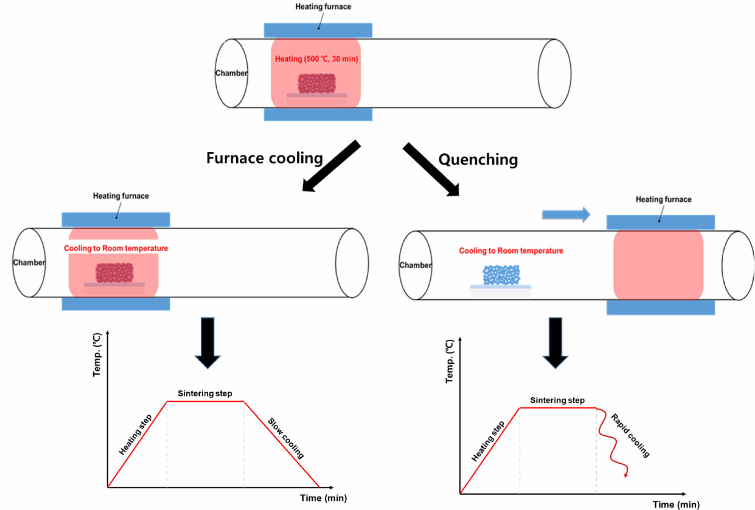
|
Fig. 1 (a) Schematic diagram of the air quenching process compared to the conventional furnace-cooling process. |
Crystallographic phases of mesoporous TiO2 films sintered at 500 oC are shown in Fig. 2. The TiO2 anatase phase (JCPDS 73-1764) and SnO2 phase (JCPDS 46-1088) were observed in both the furnace-cooled and quenched samples. The SnO2 phase comes from the FTO substrate. Based on the XRD patterns, no signi- ficant change in characteristic diffraction peaks was created due to the rapid cooling, which indicates that the quenching step during the sintering process did not induce any substantial change in the crystal structure of TiO2.
XPS analysis was performed to confirm the valence states of Ti in the TiO2 films because dye adsorption can be affected by the electronic structure of the TiO2 photoelectrode. The Ti2p core-level spectra consisted of stoichiometric doublet peaks from spin-orbit splitting corresponding to Ti2p3/2 and Ti2p1/2 states at 458.8 and 464.5 eV, respectively, as shown in Fig. 3. Upon fitting by a Gaussian method, the shoulder peak of Ti3+2p1/2 at 459.1 eV as well as stoichiometric doublet peaks of Ti4+2p3/2 and Ti4+2p1/2 were observed. This indicates that TiO2 and Ti2O3 coexist in the as-deposited TiO2 films. Moreover, no peak shift was observed, and the peak areas were similar between the furnace-cooled sample and the quenched sample. Thus, the XPS analysis showed that the surface oxidation state and chemical bonding of TiO2 films are not affected by a quenching step during the sintering process.
The HR-SEM images of the furnace-cooled and quenched TiO2 films at various sintering temperatures are shown in Fig. 4. Porous TiO2 films with nanometer-sized spherical particle necking were formed. Unlike the XRD and XPS data, microstructural changes in the TiO2 film were observed according to presence of the quenching process. The quenched TiO2 films had smaller particles compared to the furnace-cooled TiO2 films.
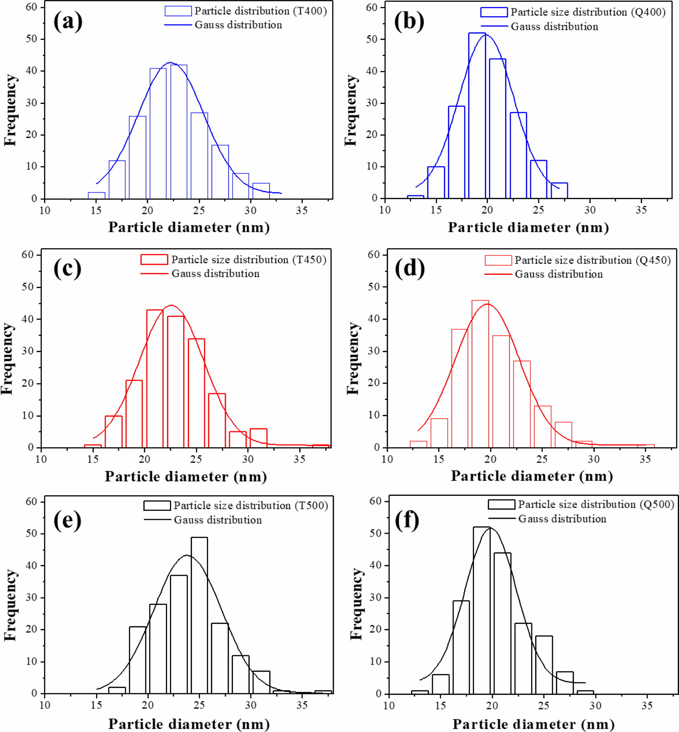
The ImageJ processing program was used to quantify the distribution of TiO2 particle size from the HR-SEM images. Fig. 5 shows the particle size distributions of the furnace-cooled and quenched TiO2 films at various sintering temperatures, and the calculated average particle diameters are listed in Table 1. The average particle size of the samples increased with sintering temperature, as shown in Fig. 5 and Table 1. However, the quenched TiO2 films had a smaller average particle diameter than did the furnace-cooled TiO2 films at the same sintering temperature. This indicates that it is possible to induce an increase in the nano-sized void while maintaining the overall photoelectrode structure by introduction of a quenching process. Therefore, decrease in particle size of TiO2 can lead to an ex- pansion of the adsorption site of the dye molecules and consequently increase the amount of dye loading.
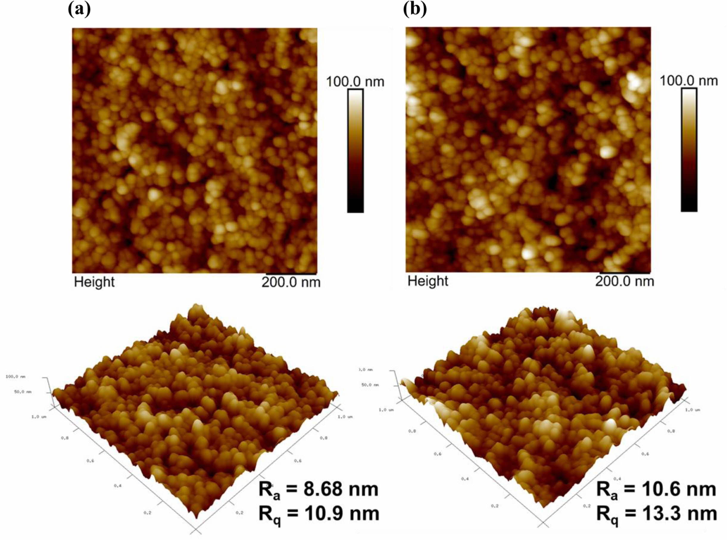
AFM images of the furnace-cooled and quenched TiO2 films at 500 oC are shown in Fig. 6. The quenched TiO2 film had a relatively rough surface with higher root-mean-square roughness (RMS) values than the furnace-cooled TiO2 film. The rough surface can enhance the active reaction area by expanding the interface between the electrolyte and the photoelectrode.
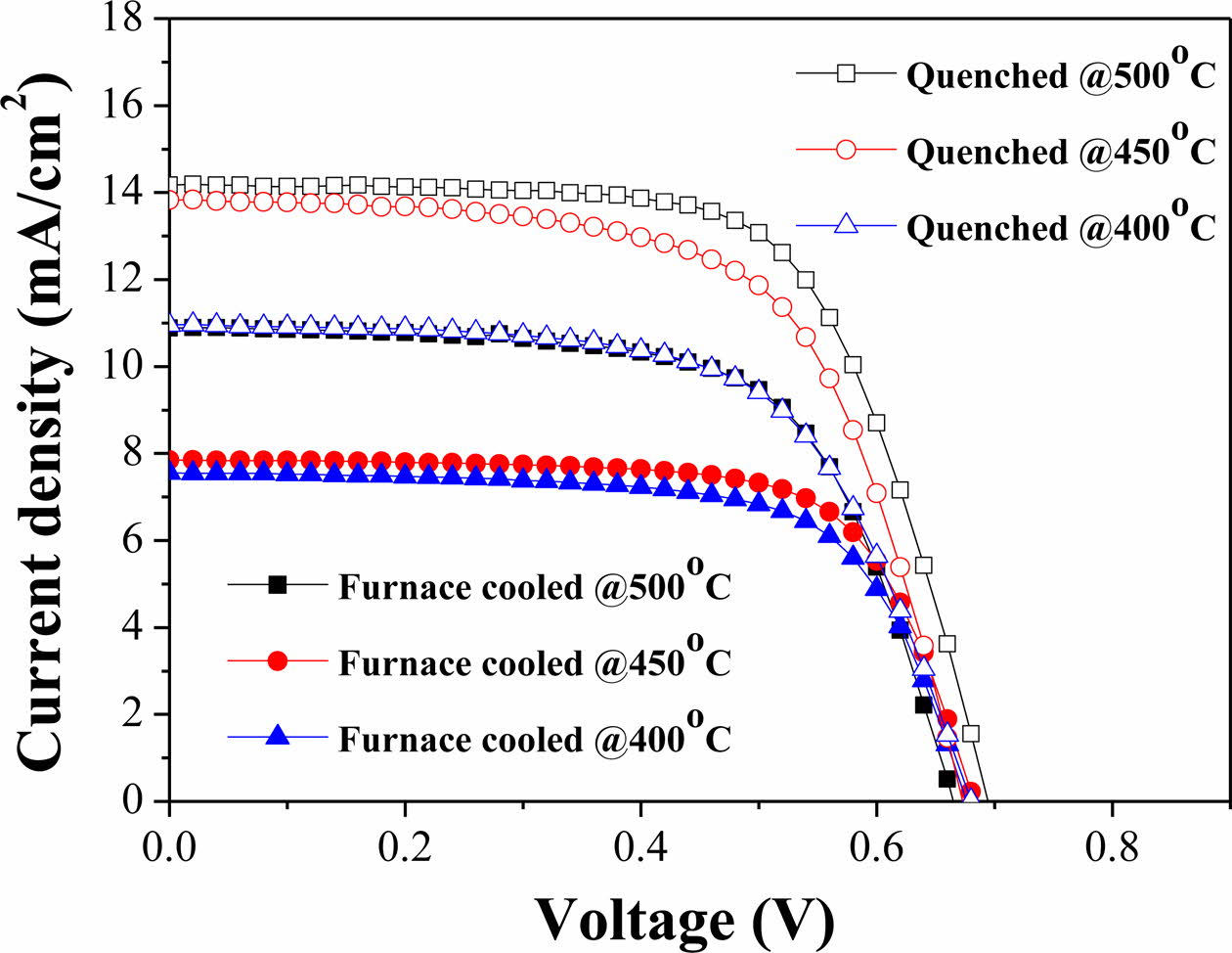
I-V characteristic measurement confirmed the perfor- mance according to change in the sintering process (Fig. 7), and the parameters are listed in Table 2. All the quenched samples showed better performance than the furnace-cooled samples at the same sintering tem- perature. The sample quenched at 500 oC exhibited the highest conversion efficiency of 5.797%. This per- formance is comparable with those of several studies (Table 2) [46-49]. The short-circuit current density (ISC) of the quenched samples increased significantly com- pared to that of the furnace-cooled samples. Generally, dyes are a key component for improvement of DSSC performance because they generate electrons when sunlight is incident on the device. Therefore, the amount of dye adsorbed on mesoporous TiO2 films is an impor- tant factor in generation and movement of electrons, which directly affects the current density and efficiency. Meanwhile, since the electricity generation mechanism of DSSCs is related closely to the electrochemical reactions, the charge transfer reaction at the TiO2-dye-electrolyte interface, which is defined as a triple phase boundary, is a critical performance factor. The electro- chemical charge transfer reaction strongly depends on the number of active reaction sites. As the number of active reaction sites increases, the charge transfer reaction proceeds more actively. Therefore, the small particle size and rough surface morphology according to intro- duction of the quenching process, as shown in Table 1 and Fig. 6, can increase the amount of dye loading and promote the charge transfer reaction, thereby improving the performance.
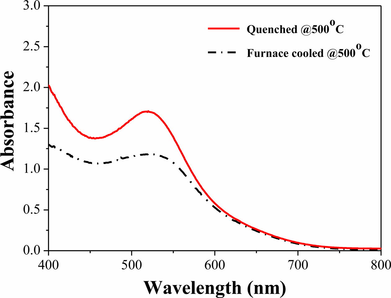
UV-visible spectroscopy analysis was performed to compare the adsorption amount of N719 dye according to sintering process of the TiO2 photoelectrode (Fig. 8). The quenched TiO2 film showed higher absorbance in the 525-535 nm wavelength range corresponding to the N719 dye molecule compared with the furnace-cooled TiO2 film. This indicates that the amount of dye ad- sorption increased by introduction of the quenching process.
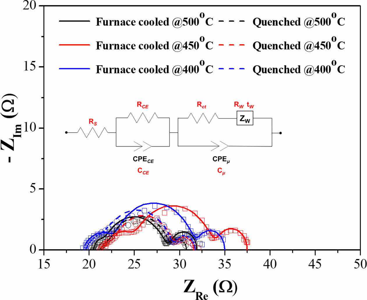
EIS analysis was used to confirm the relationship between performance of the DSSCs and electrochemical reaction. AC impedance spectra of DSSCs with the furnace-cooled and quenched TiO2 films at various temperatures are shown in Fig. 9. In general, there are typically three distinct semicircles on the Nyquist plots of DSSCs. The first semicircle in the high-frequency range, the second semicircle in the middle-frequency range, and the third semicircle in the low-frequency range are designated to redox reaction of 3I-/I3- at the Pt counter electrode (RCE), charge transfer reaction at the interface between TiO2/N719 and electrolyte (Rct), and Warburg diffusion process of iodide (Rw), respectively [50-52]. The electrochemical parameters obtained by simulation of fitting between equivalent circuit and impedance spectra from Fig. 9 are listed in Table 3. The measured impedance data (blank dots) are well matched with the simulated data (lines) calculated by the equivalent circuit. Therefore, the calculated electro- chemical parameters could be meaningful. As shown in Fig. 9, the size of the second semicircle for all the quenched samples decreased significantly compared with the furnace-cooled samples at the same sintering temperature. Similarly, the resistance values of charge transfer (Rct) and diffusion process (Rw) for all the quenched samples decreased compared with those of the furnace-cooled samples (Table 3). This result is consistent with the tendency of ISC and efficiency in I-V characteristics. Namely, introduction of the quenching process might facilitate the charge transfer reaction and diffusion process. It is also reported that the second semicircle decreases when the number of electrons generated increases [52]. As mentioned on the I-V characteristics section, since the electrochemical charge transfer reaction is related closely to the number of active reaction sites, the small particle size and rough surface morphology induced by quenching increased the number of active reaction sites and decreased the resistance of the charge transfer reaction, leading to improvement of overall DSSC performance.
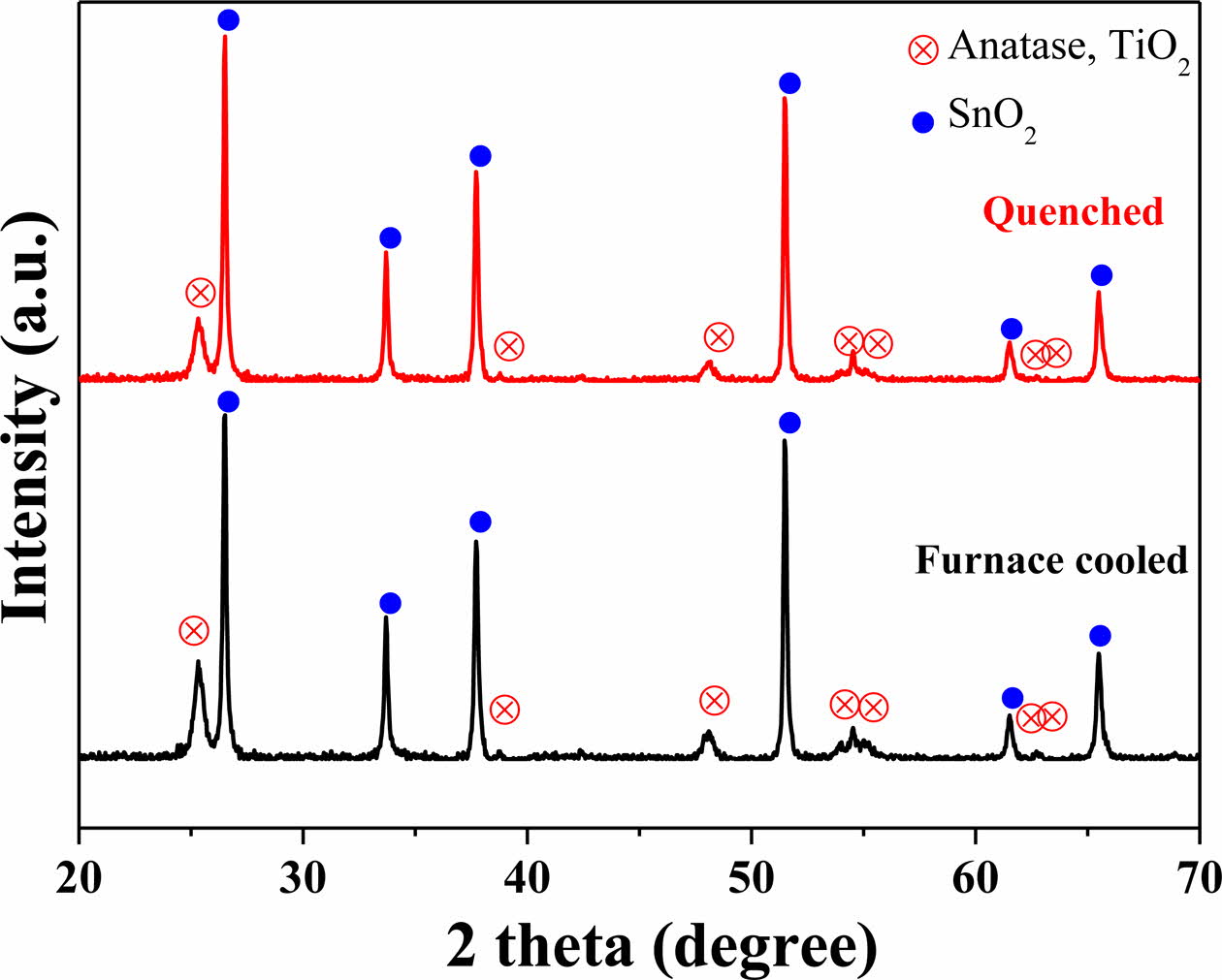
|
Fig. 2 X-ray diffraction patterns of the furnace-cooled and quenched TiO2 films at 500 oC. |
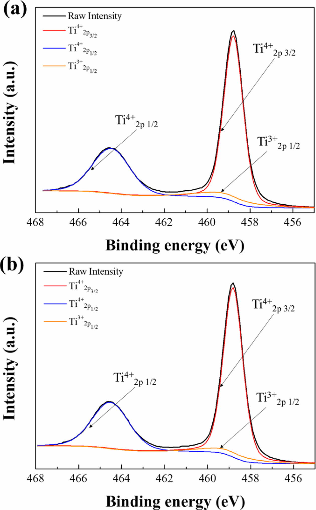
|
Fig. 3 Ti2p core-level spectra of the (a) furnace-cooled and (b) quenched TiO2 films at 500 oC. |
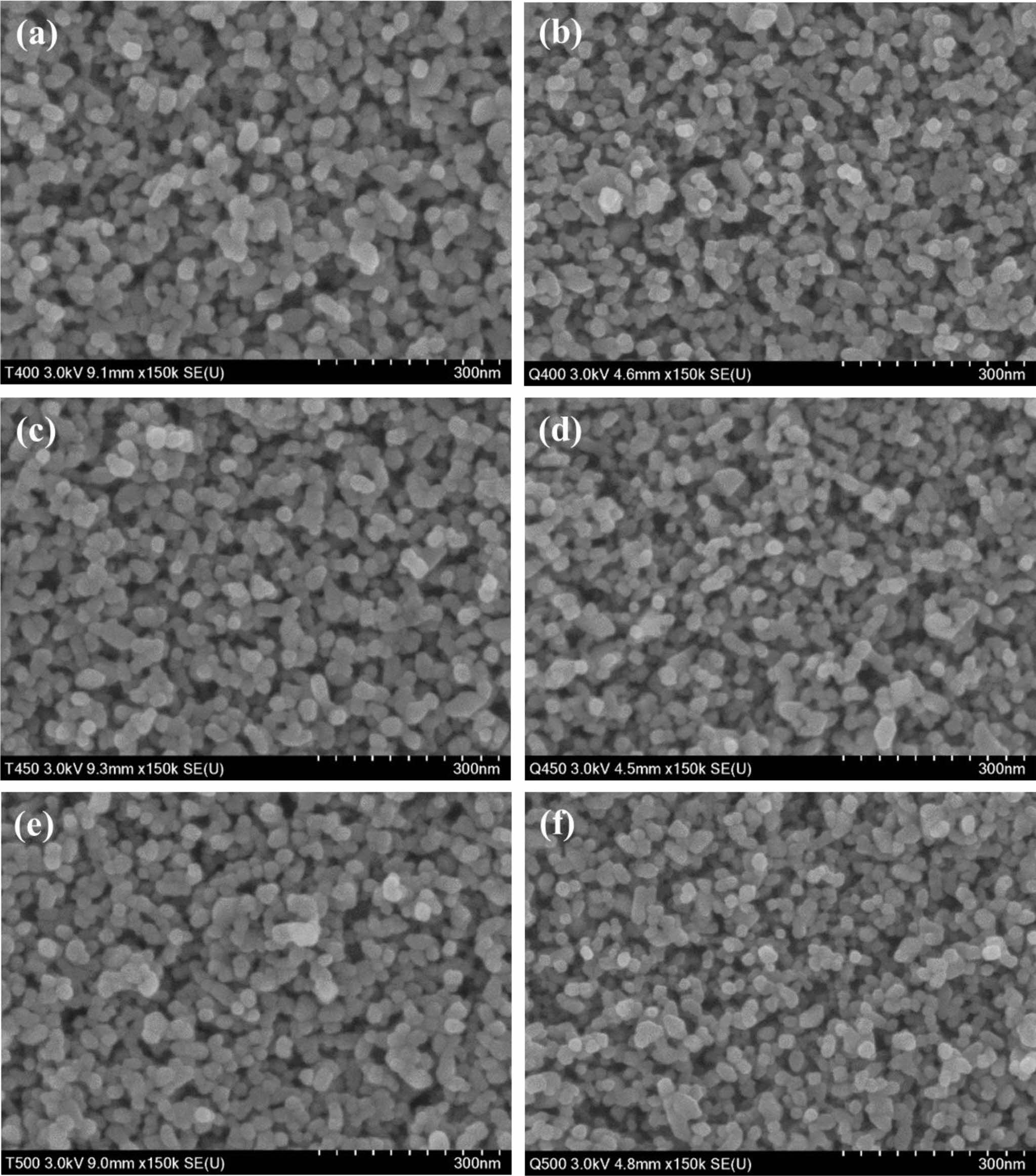
|
Fig. 4 HR-SEM surface images of (a, c, e) furnace-cooled and (b, d, f) quenched TiO2 films at various sintering temperatures; (a, b) 400 oC, (c, d) 450 oC, and (e, f) 500 oC. |
|
Fig. 5 Particle size distributions of (a, c, e) furnace-cooled and (b, d, f) quenched TiO2 films at various sintering temperatures; (a, b) 400 oC, (c, d) 450 oC, and (e, f) 500 oC. |
|
Fig. 6 AFM images of the (a) furnace-cooled and (b) quenched TiO2 films at 500 oC. |
|
Fig. 7 Photocurrent density-voltage curves of DSSCs with the furnace-cooled- and quenched TiO2 films at various temperatures. |
|
Fig. 8 UV-visible spectroscopy of N719-absorbed TiO2/FTO/ glass samples. |
|
Fig. 9 AC impedance spectra of DSSCs with the furnace-cooled and quenched TiO2 films at various temperatures (Dot: Raw data, Line: fitting data from an equivalent circuit). |
|
Table 1 Calculated average particle diameters of furnace-cooled and quenched TiO2 films at various sintering temperatures. |

|
Table 2 Short-circuit current (ISC), open-circuit voltage (VOC), fill factor (FF), and power-conversion efficiency (η) of the DSSCs according to sintering method. |

|
Table 3 Electrochemical resistance and capacitance values of illuminated DSSCs of the TiO2 photoelectrode according to sintering method under open circuit conditions. Data were obtained from EIS fits using the equivalent circuits in Fig. 9. |

The effect of the quenching process on the performance of a TiO2 photoelectrode for DSSCs was investigated. Introduction of the quenching step during sintering did not induce any change in the crystal structure or surface oxidation state of TiO2 films. However, the quenching process significantly affected the microstructure and the surface morphology of TiO2 films. The quenched TiO2 films had smaller particles and rougher surface morphology compared to the furnace-cooled TiO2 films. These microstructural and morphological changes were related to the overall DSSC performance. Based on UV-visible spectroscopy analysis, the amount of dye adsorption on the quenched TiO2 films increased com- pared with that of the furnace-cooled TiO2 films. In terms of the electrochemical reaction, microstructural and morphological changes such as small particle size and rough surface morphology caused by quenching increased the number of active reaction sites and consequently promoted the charge transfer reaction and diffusion process, improving overall DSSC performance.
This research was supported by the National Research Foundation of Korea (NRF) grant funded by the Korea government (MSIT) (No. 2020R1A2C1004580). This work was also supported by the Technology Develop- ment Program to Solve Climate Changes of the National Research Foundation (NRF) grant funded by the Korea government (Ministry of Science and ICT) (2017M1A2A2044930). This work was partly supported by Korea Institute of Energy Technology Evaluation and Planning (KETEP) grant funded by the Korea government (MOTIE) (20213030040110).
- 1. J. Gong, J. Liang, and K. Sumathy, Renew. Sustain. Energy Rev. 16[8] (2012) 5848-5860.
-

- 2. J. Gong, K. Sumathy, Q. Qiao, and Z. Zhou, Renew. Sustain. Energy Rev. 68 (2017) 234-246.
-

- 3. M.S. Ahmad, A.K. Pandey, and N.A. Rahim, Renew. Sustain. Energy Rev. 77 (2017) 89-108.
-

- 4. K. Sharma, V. Sharma, and S.S. Sharma, Nanoscale Res. Lett. 13[1] (2018) 381.
-

- 5. S. Thomas, T.G. Deepak, G.S. Anjusree, T.A. Arun, S.V. Nair, and A.S. Nair, J. Mater. Chem. A 2[13] (2014) 4474-4490.
-

- 6. K.H. Ko, Y.C. Lee, and Y.J. Jung, J. Colloid Interface Sci. 283[2] (2005) 482-487.
-

- 7. W. Wunderlich, T. Oekermann, L. Miao, N.T. Hue, S. Tanemura, and M. Tanemura, J. Ceram. Process. Res. 5[4] (2004) 343-354.
- 8. X. Feng, K. Shankar, O.K. Varghese, M. Paulose, T.J. Latempa, and C.A. Grimes, Nano Lett. 8[11] (2008) 3781-3786.
-

- 9. Y. Jiang, M. Li, R. Ding, D. Song, M. Trevor, and Z. Chen, Mater. Lett. 107 (2013) 210-213.
-

- 10. B.H. Lee, M.Y. Song, S.-Y. Jang, S.M. Jo, S.-Y. Kwak, and D.Y. Kim, J. Phys. Chem. C 113[51] (2009) 21453-21457.
-

- 11. J.M. Macak, H. Tsuchiya, A. Ghjcov, and P. Schmuki, Electrochem. Commun. 7[11] (2005) 1133-1137.
-

- 12. S.I. Noh, T.-Y Seong, and H.J. Ahn, J. Ceram. Process. Res. 13[4] (2012) 491-494.
- 13. J. Navas, C. Fernadez-Lorenzo, T. Agulilar, R. Alcantara, and J. Martin-Calleja, Phys. Status Solidi A 209[2] (2012) 378-385.
-

- 14. Q. Liu, Y. Zhou, Y. Duan, M. Wang, and Y. Lin, Electrochim. Acta 95 (2013) 48-53.
-

- 15. M.S. Mahmoud, M.S. Akhtar, I.M.A. Mohamed, R. Hamdan, Y.A. Dakka, and N.A.M. Barakat, Mater. Lett. 225 (2018) 77-81.
-

- 16. P. Wang, S.M. Zakeeruddin, J.E. Moser, R. Humphry-Baker, P. Comte, V. Aranyos, A. Hagfeldt, M. K. Nazzeruddin, and M. Gratzel, Adv. Mater. 16[20] (2004) 1806-1811.
-

- 17. W. Zeng, Y. Cao, Y. Bai, Y. Wang, Y. Shi, M. Zhang, F. Wang, C. Pan, and P. Wang, Chem. Mater. 22[5] (2010) 1915-1925.
-

- 18. S. Chinnasamy and S. Ramanathan, J. Ceram. Process. Res. 21[1] (2020) 123-130.
-

- 19. C.M. Elliott, Nat. Chem. 3[3] (2011) 188-189.
-

- 20. P. Wang, S.M. Zakeruddin, I. Exnar, and M. Gratzel, Chem. Commun. 24 (2002) 2972-2973.
-

- 21. M.-J. Jeng, Y.-L. Wung, L.-B. Chang, and L. Chow, Int. J. Photoenergy 2013 (2013) Article ID 563897.
-

- 22. Y.J. Son, J.S. Kang, J.J. Yoon, J. Kim, J.W. Jeong, J.H. Kang, M.J. Lee, H.S. Park, and Y.-E. Sung, J. Phys. Chem. C 122[13] (2018) 7051-7060.
-

- 23. W.Y. Park and K.T. Lee, J. Ceram. Process. Res. 22[5] (2021) 584-589.
-

- 24. S. Ito, P. Chen, P. Comte, M. K. Nazeeruddin, P. Liska, P. Pechy, and M. Gratzel, Prog. Photovolt.: Res. Appl. 15[7] (2007) 603-612.
-

- 25. A.I. Kontos, A.G. Kontos, D.S. Tsoukleris, M.-C. Bernard, N. Spyrellis, and P. Falaras, J. Mater. Process. Technol. 196[1-3] (2008) 243-248.
-

- 26. B. Roose, S. Pathak, and U. Steiner, Chem. Soc. Rev. 44[22] (2015) 8326-8349.
-

- 27. R. Sanjines, H. Tang, H. Berger, F. Gozzo, G. Margaritondo, and F. Levy, Int. J. Appl. Phys. 75[6] (1994) 2945-2951.
-

- 28. B. O’Regan and M. Gratzel, Nature 353[6346] (1991) 737-740.
-

- 29. Y.J. Kim, M.H. Lee, H.J. Kim, G. Lim, Y.S. Choi, N.-G. Park, K.K. Kim, and W.I. Lee, Adv. Mater. 21[36] (2009) 3668-3673.
-

- 30. R. Govindaraj, M.S. Pandian, P. Ramasamy, and S. Mukhopadhyay, Bull. Mater. Sci. 38[2] (2015) 291-296.
-

- 31. T.P. Chou, Q. Zhang, B. Russo, G.E. Fryxell, and G. Cao, J. Phys. Chem. C 111[17] (2007) 6296-6302.
-

- 32. K.S. Park, Q. Zhang, D. Myers, and G. Cao, ACS Appl. Mater. Interfaces 5[3] (2013) 1044-1052.
-

- 33. S. Nakade, Y. Saito, W. Kubo, T. Kanzaki, T. Kitamura, Y. Wada, and S. Yanagida, Electrochem. Commun. 5[9] (2003) 804-808.
-

- 34. S. Nakade, Y. Saito, W. Kubo, T. Kitamura, Y. Wada, and S. Yanagida, J. Phys. Chem. B 107[33] (2003) 8607-8611.
-

- 35. S.C. Yang, D.J. Yang, J.K. Kim, J.M. Hong, H.G. Kim, and I.D. Kim, Adv. Mater. 20 (2008) 1059-1064.
-

- 36. S. Muduli, O. Game, V. Dhas, K. Vijayamohanan, K.A. Bogle, N. Valanoor, and S.B. Ogale, Solar Energy 86[5] (2012) 1428-1434.
-

- 37. K. Guo, M. Li, X. Fang, X. Liu, B. Sebo, Y. Zhu, Z. Hu, and X. Zhao, J. Power Source 230 (2013) 155-160.
-

- 38. N. Chander and M.R. Samantaray, IEEE J. Photovoltaics 11[5] (2021) 1213-1221.
-

- 39. C.A. Leach, P. Tanev, and B.C.H. Steele, J. Mater. Sci. Lett. 5[9] (1986) 893-894.
-

- 40. K. Niesz, T. Ould-ely, H. Tsukamoto, and D.E. Morse, Ceram. Int. 37[1] (2011) 303-311.
-

- 41. . Zhang, J. Zheng, Y. Liu, C. Zhang, W. Hao, Z. Lei, and M. Tian, Mater. Res. Bull. 115 (2019) 49-54.
-

- 42. .C. Maurya, S. Senapati, S. Singh, P. Srivastava, P. Maiti, and L. Bahadur, Chemistry Select. 3[34] (2018) 9872-9880.
-

- 43. M.J. Jeng, Y.L. Wung, L.B. Chang, and L. Chow, Int. J. Photoenergy 2013 (2013) Article ID 280253.
-

- 44. V.A. González-Verjan, B. Trujillo-Navarrete, R.M. Félix-Navarro, J.D. de León, J.M. Romo-Herrera, J.C. Calva-Yáñez, J. M. Hernández-Lizalde, and E.A. Reynoso-Soto, Mater. Renew. Sustain. Energy 9 (2020) 1-8.
-

- 45. Z.S. Wang, H. Kawauchi, T. Kashima, and H. Arakawa, Coord. Chem. Rev. 248[13-14] (2004) 1381-1389.
-

- 46. S.N. Karthick, K.V. Hemalatha, C.J. Raj, H.-J. Kim, and M. Yi, J. Ceram. Process. Res. 13[S1] (2012) 136-139.
- 47. A. Aboulouard, B. Gultekin, M. Can, M. Erol, A. Jouaiti, B. Elhadadi, C. Zafer, and S. Demic, J. Mat. Res. Tech. 9[2] (2020) 1569-1577.
-

- 48. Y. Kim, B.J. Yoo, R. Vittal, Y. Lee, N.-G. Park, and K.-J. Kim, J. Power Sources 175[2] (2008) 914-919.
-

- 49. D. Kim, K. Lee, H. Lee, J. Lim, and J. Park, J. Kor. Cryst. Growth and Cryst. Tech. 30[2] (2020) 61-65.
-

- 50. C.-P. Hsu, K.-M. Lee, J.T.-W. Huang, C.-Y. Lin, C.-H. Lee, L.-P. Wang, S.-Y. Tasi, and K.-C. Ho, Electrochim. Acta 53[25] (2008) 7514-7522.
-

- 51. R. Kern, R. Sastrawan, J. Ferber, R. Stangl, and J. Luther, Electrochim. Acta 47[26] (2002) 4213-4225.
-

- 52. S. Sarker, A.J.S. Ahammad, H.W. Seo, and D.M. Kim, Int. J. Photoenergy 2014 (2014) Article ID 851705.
-

 This Article
-
2022; 23(2): 199-207
Published on Apr 30, 2022
- 10.36410/jcpr.2022.23.2.199
- Received on Oct 28, 2021
- Revised on Dec 30, 2021
- Accepted on Jan 10, 2022
 Services
- Abstract
introduction
experimental procedure
results and discussion
conclusions
- Acknowledgements
- References
- Full Text PDF
Shared
 Correspondence to
- Ki-Tae Lee
-
aDivision of Advanced Materials Engineering, Jeonbuk National University, Jeonbuk 54896, Republic of Korea
bDepartment of Energy Storage/Conversion Engineering of Graduate School (BK21 FOUR), Jeonbuk National University, Jeonbuk 54896, Republic of Korea
cHydrogen and Fuel Cell Research Center, Jeonbuk National University, Jeonbuk 54896, Republic of Korea
Tel : +82-63-270-2290 Fax: +82-63-270-2386 - E-mail: ktlee71@jbnu.ac.kr


 Copyright 2019 International Orgranization for Ceramic Processing. All rights reserved.