- Effect of pyrolysis sintering temperature on the electrical current delivery power of kaolin-carbon composites
Agus Edy Pramonoa,*, Sidiq Ruswantoa and Nanik Indayaningsihb
aDepartment of Mechanical Engineering, Politeknik Negeri Jakarta, Jln. Prof. Dr. G.A. Siwabessy, Kampus UI. Depok 16425, West Java, Indonesia
bResearch Centre for Physics, Indonesian Institute of Sciences, Puspiptek Area, Gd. 440-442, South Tangerang, Banten 15310, IndonesiaThis article is an open access article distributed under the terms of the Creative Commons Attribution Non-Commercial License (http://creativecommons.org/licenses/by-nc/4.0) which permits unrestricted non-commercial use, distribution, and reproduction in any medium, provided the original work is properly cited.
An investigation of engineered composites of kaolin and synthetic carbon has been conducted. The composite was developed from local kaolin materials from Singkawang, West Kalimantan, Indonesia, and synthetic carbon from organic coconut coir waste. The study is intended to determine the electrical conductivity properties of these engineering materials. Density values due to the increase in sintering temperature are relatively the same and stable at adjacent values. The increase in pyrolysis sintering temperature does not change porosity significantly; porosity that occurs in carbon-ceramic composites at each composition ratio tends to be stable at adjacent values. The higher the sintering temperature, the higher the electric current that can flow in carbon ceramics. The micro-features contained in the composite bulk show porosity and cracks, and disconnection of connectivity between the filler carbon powder
Keywords: Kaolin-carbon composite, Electrical conductivity, Electric current-voltage, Sintering pyrolysis, Coconut coir carbon
The study examines fabricated ceramic composite materials' electrical current delivery properties from kaolin mixtures as matrices and synthetic carbon as fillers. This study is material engineering that can still be developed for functional materials according to the properties required in their application. For example, one application of the study results is for carbon-strip components used in electric circuit train pantographs, carbon-strips for conductors on crane wire contactors strip, and much more. This engineering can also be developed into membranes from ceramics, especially for gas applications, due to high thermal stability, good chemical compatibility [1].
The shape and dimensions of the research sample have not yet followed the geometry of the components in question. The research was developed from local kaolin materials from Singkawang, West Kalimantan, Indonesia, and synthetic carbon from the organic waste of coconut coir.
Sintering in the research process is heating at high temperatures but does not cause melting in the primary material, namely kaolin and synthetic carbon, as filler material of carbon ceramic composites. The pyrolysis sintering process in this study is a sintering process that keeps the heated material unoxidized so that synthetic carbon fillers do not turn into ash. Some studies that have been done can be a reference comparison and show the results of sintering pyrolysis. The composite combustion properties of the kaolin material, the Al2O3 content in kaolin will react when mixed with a bit of water to achieve plastic properties and form a mullite phase when the sintering process is carried out to remove the gas trapped inside the composite. The study fabricated disk samples from a white clay from Yanggu at 1100 oC. 1100 oC sintering process confirmed no gas trapped [2]. Green ceramic composites are consolidated with different starches and are sintered at different tem- peratures in the argon atmosphere. Electrical measure- ments, carbon content, and Raman analysis of carbon structures determine an optimal sintering temperature of 1700 oC, resulting in the uniform formation of conductive graphite tissue in porous composites with high electrical conductivity [3]. Improvements in the mechanical properties of Al2O3 porous ceramics from colloidal suspension with the addition of carbon fibre with direct foaming are being studied in this study. Dry green sample material sintered in a super kantal furnace at a high temperature of 1500 oC for 1 hour, at a rate of 1 oC/min and cooling at a rate of 3 oC/min [4]. The process of making soji using kaolinite is like the process of making soji porcelain in general. The specimen is dried for 24 hours at room temperature. The specimen is heated in an electric furnace, a rate of 3 oC/min; and stored at a high temperature (1200 oC/1250 oC) for 60 min. Sintering is performed in a CO 2.0% controlled atmosphere using gases in an electric furnace or an oxidizing atmosphere (air). Microstructure after sintering is observed using an electron microscope, the rate of shrinkage/dredging of sintered specimens is measured [5]. The development of new composites uses kaolin clay for strong chemical bonds of heavy metal sludge washing industrial uniforms. Composition of sludge content material of laundry waste up to 20% of the weight sintered at a temperature of 1100 - 1150 - 1200 - 1250 and 1300 oC [6]. The porous ceramic mem- brane for the nanofiltration range is made from clay spherical grains and starches. The Sayong ball clay powder is mixed with starch as a pore shaper and solidified at a pressure of 200 MPa. The mixture is processed sinter at temperatures ranging from 900 oC to 1200 oC. It was found that the porous structure and crystal phase of the sintered membrane depended heavily on the temperature of the sintering [7]. The materials used in the study were kaolin and high-density polyethylene powder. Kaolin clay is mixed with high-density polyethylene powder. The flour mixture is compacted, becoming a membrane, with a hydraulic press at a pressure of 3.5 MPa; processed sintering at 1150 oC for 4 hours in a dampening furnace at five oC/ min [1]. Sintering reactions make Mullite-based ceramics from mixtures containing kaolin clay and kaolin waste. Sintering shrinkage behaviour is monitored with dilato- metry. Ceramic samples made with kaolin waste showed better physical-mechanical properties than pure kaolin clay for sintering up to 1400 oC [8]. Porous mullite ceramics are made from kaolin and Al2O3 with different sintering additives TiO2, MgO and MoO3.
The help of the sintering process significantly influences grain morphology and densification processes by varying the composition and viscosity of the liquid phase during combustion [9]. High-performance mullite ceramics are made from high aluminium fly ash without any additional material through a series of steps. The original fly ash has been processed first with alkalis and acids to adjust its chemical composition. Furthermore, the physical properties and phase transformations of the sample are prepared at different sintering temperatures. Green com- pacts are sintered at different temperatures (1200-1600 oC) for 2 hours and then cooled naturally [10]. Most sintering processes have been done only to change kaolin and unite other materials to become ceramic. This study describes the sintering process combined with pyrolysis. This process is done to convert kaolin into ceramic while also protecting carbon fillers. The sintering process converts kaolin into ceramic mullite, and the pyrolysis process protects the filler carbon from oxidizing to ash. Furthermore, carbon-ceramic composites become electrically conductive.
Material
The carbonization process prepares the synthetic carbon material from coconut coir organic waste material. The carbonization process is carried out in an airtight tube with an electric furnace at a temperature of 950 oC, a speed of 2 oC/min, and natural cooling. The process produces synthetic carbon that can conduct electricity. The selection of a carbonization temperature of 950 oC based on previous research on carbonization at that temperature results in relatively high electrical conductivity [11]. Coconut coir carbon powder is pounded and sifted to reach mesh #250. Kaolin is a local mining material from Singkawang, West Kalimantan, Indonesia. The miner company has prepared the dry powder kaolin material with #325 mesh.
Material characteristics
The X-ray Fluorescence Analyzer TORONTECH TT characterizes kaolin - EDXPRTtool to ascertain the content of the elements; testing was conducted at the Indonesian Institute of Sciences (LIPI) physics laboratory, Serpong. The main content of kaolin is Si (67.1% weight), Al (27.4% weight); the rest is shown in Table 1. Another article shows almost the same content of kaolin elements, but in different percents; This researcher showed the results of kaolin test with SiO2 content of 45.80% mass [12]; researcher Katsuki H. showed SiO2 content of 45.26% mass [2]; In general, the largest content of kaolin is Si, as shown in this reference article, SiO2 ±49.4%. [5]; SiO2 47.10 %wt [13]; SiO2 71.50% [6].
Kaolin density shows 2.31±0.07 [gram/cm3], this reference also shows almost the same density value, 2.40 to 2.74 [gram/cm3] [14].
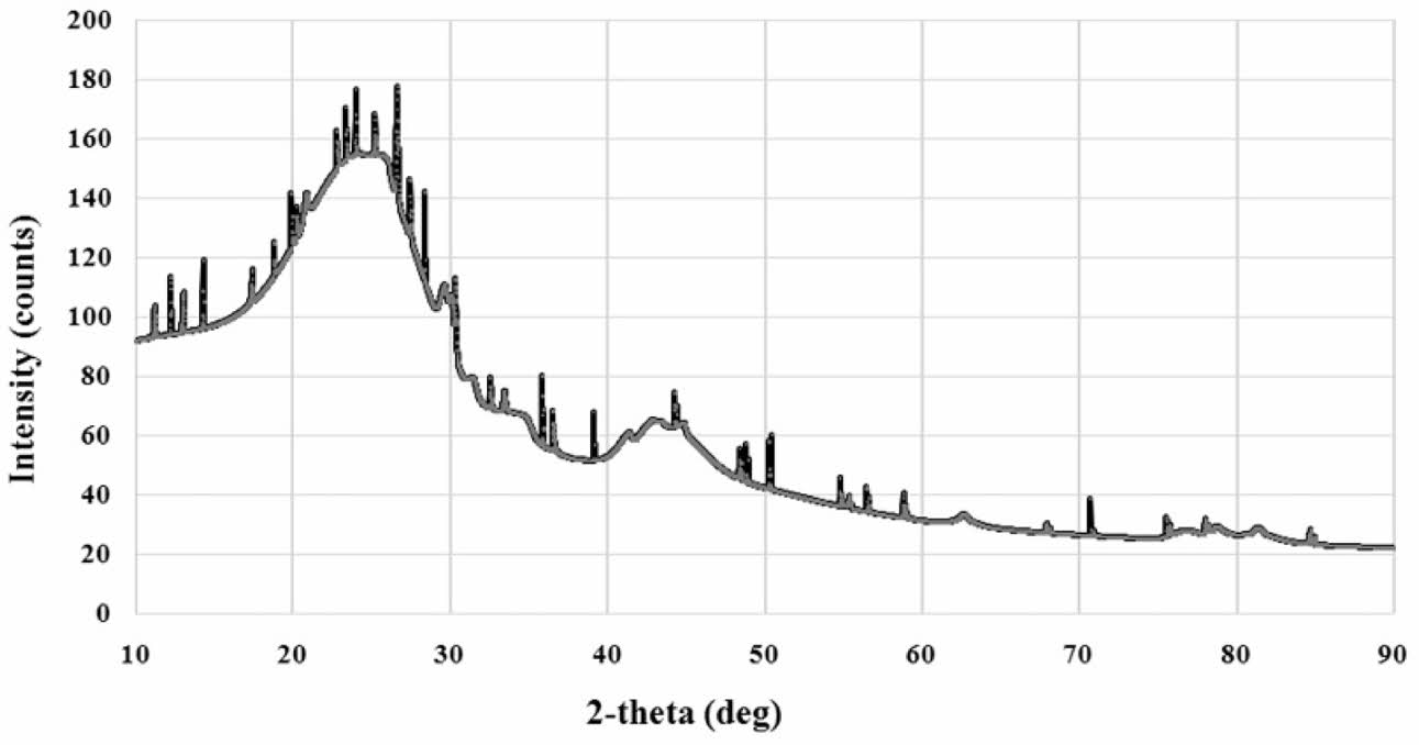
Carbon characteristic testing is done with XRD, with the profile shown in Fig. 1. The XRD test profile shows the structure of carbon materials with irregular atomic arrangements. The highest intensity is at an angle of 2θ = 24.25o. Other researchers also showed the carbon XRD test results that are close to the same, that the structure of the carbon material is amorphous. In this test two weak maxima diffractions showed negligible crystal phase content,especially at an angle of 2θ between 40-50o [15]. Organic waste carbon density tests showed 1.3794±0.12 [grams/cm3].
Sample fabrication
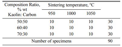
The ratio of mixture composition between carbon powder and kaolin is designed to be 50:50; 40:60; and 30:70, and the addition of water is sufficient to form plastic properties. The green compact is done with a hydraulic press with a pressure of 200 bars into a tablet measuring 40 mm Ø x 10 mm thick. Green compact tablets processed pyrolysis sintering at varying temper- atures of 950; 1000; 1050 oC, performed in a furnace with an airtight reactor tube, at a temperature speed of 2 oC/min, produced a carbon kaolin composite specimen, the number of specimens shown in Table 2. The selection of pyrolysis sintering temperature is based on consi- deration of the mullite formation of kaolin. Mullite is produced during the combustion or sintering process. The base material of mullite is kaolinite clay and is processed sinter at temperatures above 1100 oC. Mullite can form in ceramics during sintering and will improve mechanical strength and thermal shock resistance. Mullite is used as a fire-retardant material due to its high melting point of 1840 oC. Some studies show the process of sintering at about the same temperature. The heating rate is three oC·min-1 from room temperature to 950 oC and four oC·min-1 to the final temperature. A 1-hour holding time is carried out at 950 oC to encourage mullite formation [9]. Sintering reactions make Mullite-based ceramics from mixtures containing kaolin clay and kaolin waste. Compared to pure kaolin clay, ceramic samples made with kaolin waste showed better physical-mechanical properties (due to sintering up to 1400 oC) [8]. Korean white clay and kaolin were burned at 1000, 1100, 1200, and 1300 oC, the formation of mullite and quartz was observed [2]. Researcher Liu et al. showed XRD and FTIR analysis results that aluminium-silicon and amorphous silica spinels, respectively, turned into mullite and cristobalite after decomposition at 900 ºC [16]. The sintering at higher temperatures (i.e. 950 oC, 1150 oC) indicates the presence of the mullite phase due to the densification process at that temperature, and the kaolin is transformed into the mullite phase [17].
Testing the nature of electricity
The test will generate data on the electric current flowing through a carbon-ceramic composite sample with a voltage arrangement. The test was conducted at the physics laboratory of the Indonesian Institute of Sciences (LIPI) Serpong with a four-point probe method and Keithley instruments tool, The 2450 SourceMeter® Instrument.
Testing the electrical properties with the four-point probe method follows the ASTM D4496 standard. Testing is done to determine the electrical current delivery power, voltage, and resistance, and further electrical delivery power from carbon-ceramic materials [15, 12]. The resistance of a material depends on the voltage and current given to the material and follows the equation (1),

Measurement of electrical conductivity follows the ASTM D257 standard. Measurements were made against electrical resistance, specimen thickness, and cross-sectional area of specimens for electrical flow. Electrical static resistance is calculated by equations (2),

The amount of electrical conductivity is determined by equation (3),

Density test
Density testing is done to determine the density of kaolin-carbon composites. The test was conducted experimentally using the Archimedes method based on the DIN-51097 standard. Carbon ceramic composite density calculated by equation (4),

Porosity test
Porosity testing follows ASTM standard C20 - 00 (2015). Visible porosity, P-Visible porosity, is the per- centage of open pore volume relationship in a specimen to its exterior volume. Porosity is calculated by equations (5),

Note: rComposite = composite density [g/cm3]; rDistillation water= density of distillation water 0.992 [g/cm3]; W1 = dry composite bulk weight; W2 = composite weight saturated water in the air; W3 = composite weight saturated water in water.
Sample mass in dry conditions (W1) weighed first. Next, the sample is soaked in a measuring glass con- taining distilled water until no air bubbles arise to ensure all pores are filled with water. Then the bulk composite saturated distillation water is weighed open (aired) (W2), the saturated composite of distillation water is weighed in distillation water (W3).
Morphology Test
Morphological tests were conducted with microscopic scanning electron Hitachi SU 3500 at the physics laboratory of the Indonesian Institute of Sciences (LIPI), Serpong, Banten, Indonesia. This test is done to determine the morphological condition of ceramic-carbon composites on a micro-scale. Based on morphology can be known geometric shapes of particles, both matrix and carbon particles, can be known the interface between particles, and the appearance of cavities that cause porosity in ceramics can be known.
|
Fig. 1 XRD of carbon |
Densities
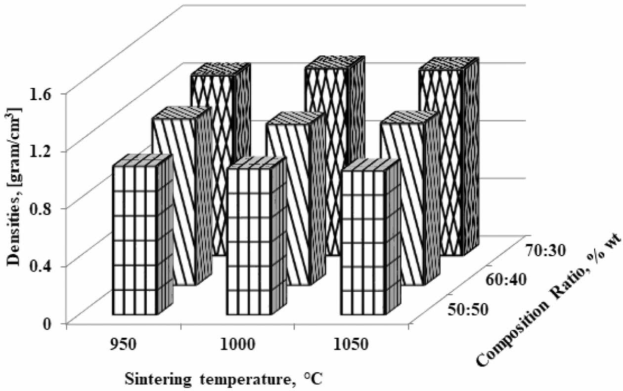
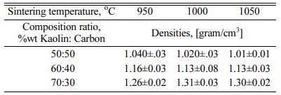
Density is an important physical property to explain the densification of materials. On the other hand, porosity is one of the critical factors that determine the performance of the membrane [7]. Based on the mea- surement of the carbon-ceramic composite densification, the level of connectedness between carbon particles and thus will be known as the level of the electrical current delivery of this carbon-ceramic composite. Fig. 2 showing the highest density is the kaolin-carbon composite with a composition ratio of 70:30 %wt and pyrolysis sintering at 1000 oC, with a density of 1.3 [grams/cm3]. The lowest density is at a composition ratio of 50:50% wt and a temperature of 1050 oC. The increase in the temperature of pyrolysis sintering does not change density significantly. Density tends to be stable at relatively equal values. Due to the increase in sintering temperature, density values are relatively the same and stable at adjacent values, as shown in Table 3. Meanwhile, the increase in kaolin weight changes the density to be even higher. This fact is natural because the density of kaolin is indeed higher than the density of carbon. The higher volume content of carbon weight makes carbon ceramic composites lighter. In comparison, some studies on clay and kaolin showed density values that approached this study. Research on membranes fabricated from clay powder and starch shows bulk densities varying from 1.5 g/cm3 to 1.9 g/cm3 [7]. Membranes sintered at higher temperatures (i.e. 950 oC and 1150 oC) indicate a mullite phase due to the densification process of the membrane structure at higher temperatures, and kaolin is transformed into the mullite phase [17].
Porosities
Porous ceramics are used in many structural appli- cations. The voltage that occurs in ceramic parts that experience this condition is determined by the mechanical properties of the component material. Porous ceramics have an essential role as a favourable thermal insulation material with unique properties such as lightweight, low thermal conductivity, light. However, typical porous ceramics have relatively low strength [4].
However, in the context of this study, porosity is described as an electrical current delivery resistance because porous cavities sever connectivity between particles, making it less electrically conductive.
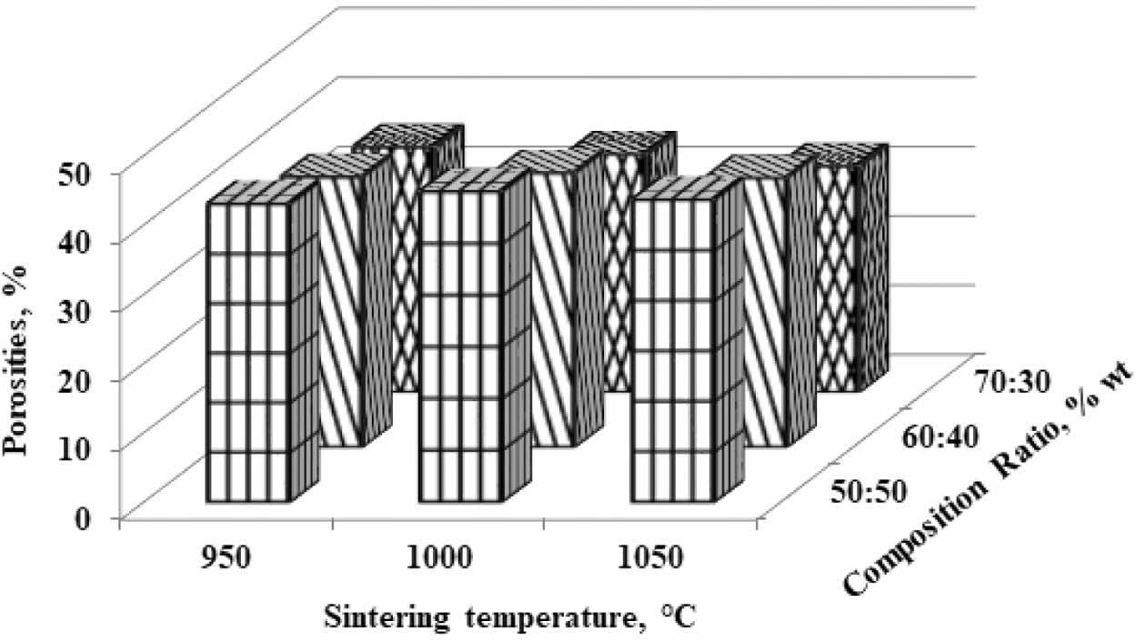
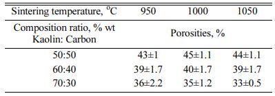
The highest porosity is indicated by a composition ratio of 50:50% weight; sintering temperature of 1050 oC, with a porosity of 44%. This value indicates that the composite contains a pore cavity amounting to 44% of the volume. The increase in sintering temperature did not significantly change the porosity of the composite. At the same time, the volume of kaolin weight affects the percentage of porosity. The higher the volume of kaolin weight, the lower the composite porosity value. This fact is normal because theoretically, the tendency of porosity values is opposite to the density value. The lowest value of 33% is indicated by a composition ratio of 70:30% weight at 1050 oC. This fact also raises the suspicion that carbon contains a lot of porous. The increase in pyrolysis sintering temperature does not change porosity significantly; porosity that occurs in carbon-ceramic composites at each composition ratio tends to be stable at adjacent values, as shown in Table 4. In comparison, some studies show the following.
The primary purpose of this work is to make a porous ball clay membrane. Corn starch serves as a porosity-forming agent. Samples are sintered at different tem- peratures ranging from 900 oC - 1200 oC; held for 2 hours in the air, resulting in porosity of up to 40% [7]. By sintering at that temperature, organic corn starch will become the carbon that forms the porosity of the membrane. Cordierite ceramic membranes are made from natural clay, oxides, and organic waste as pore-forming materials. The mixture of the above ingredients with pore-forming materials (up to 10% in weight) is investigated 19. Cheap ceramic supports are made from kaolin in different kaolin content ranging from 14 to 39 wt.%, disinter at 1200 oC, the effect of kaolin particle size and kaolin content on membrane structure is in- vestigated, and shows porosity of 27.7% [20]. Comparing Fig. 2 about density and Fig. 3 about porosity will show an increased porosity when the density decreases. A low density would otherwise indicate high water absorption and thus indicate high porosity [2].
Electrical properties
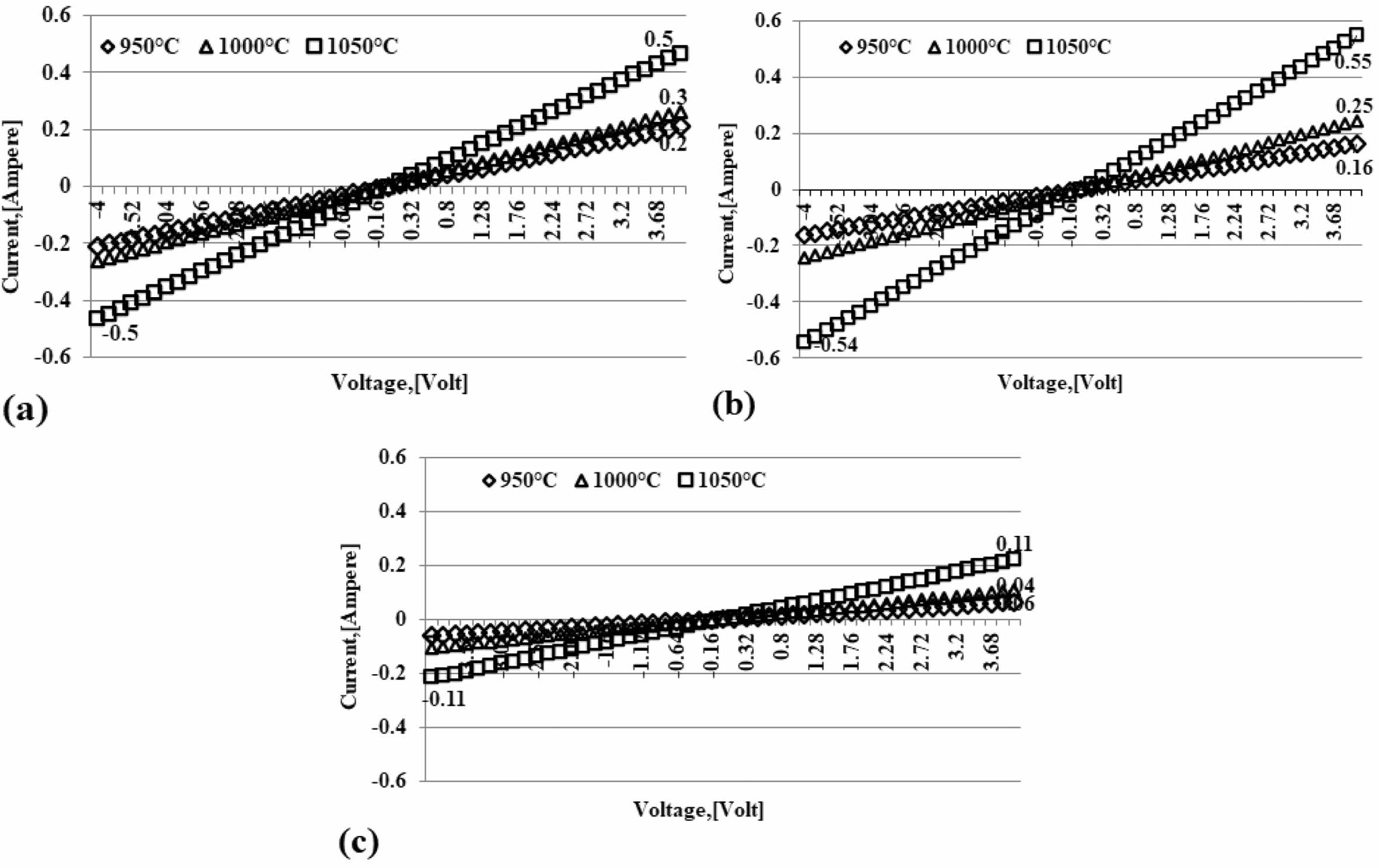
Studies of ceramic carbon composites that can conduct electricity have been widely done with nanoscale carbon. Ceramic carbon composites (CCCs) utilize carbon as a conduction phase and can be used as resistors for high voltage electrical applications. However, a challenge is a uniform dispersion of nano-sized black carbon that conducts electricity in a ceramic matrix leading to a percolation network at the lowest possible volume fraction [21]. The study focused on the high carbon content of the epoxy matrix to improve the electrical conductivity of composites [22]. Ceramic carbon com- posites with electrically conductive carbon have been made by processing dry and wet powders. The study is a composite development for applications requiring thermal shock-resistant ceramic materials that conduct electricity [23]. The test was conducted at the physics laboratory of the Indonesian Institute of Sciences, Serpong, and The Keithley Instrument, the 2450 Source Meter® Instrument. Electrical testing using the probe's four-point method follows the ASTM D4496 standard. Graphics in Fig. 4(a); (b); (c) shows the amount of electric current flowing through the carbon-ceramic by regulating the voltage. The higher the sintering temper- ature, the higher the electric current that can flow in carbon ceramics. The higher the volume of kaolin, the lower the electric current that can flow. This condition is normal because kaolin (ceramic) is an insulator. As shown in Fig. 4. At a kaolin-carbon composition ratio of 50:50 %weight, (Fig. 4(a)) shows that a controlled voltage of 4 [volts] produces an electric current flowing at 0.5 [Ampere], 0.3 [Ampere], and 0.2 [Ampere], se- quentially at pyrolysis sintering temperatures of 1050, 1000, 950 oC. At a composition ratio of 50:50% wt, this smallest current is produced at a temperature of 950 oC. With a carbon content of 40% weight, at a sintering temperature of 1050 oC, it produces an electric current flow of 0.6 [Ampere], at a controlled voltage of 4 [volts].
Meanwhile, at pyrolysis, sintering temperatures of 950 oC and 1000 oC produces an electric current flow of 0.2 and 0.3 [Ampere], relatively equal to composites with a composition ratio of 50:50% weight, this is shown in Fig. 4(b). The lowest electric current flow is shown in Fig. 4(c); this carbon-ceramic composite is formed with a composition ratio of 70% kaolin and 30% carbon weight, with a voltage flow of 4 [volts], in the sintering process 950 oC conducts an electric current of 0.05 [Ampere], the sintering process is 1000 oC capable of flowing a 0.06 [Ampere] sintering process, and 0.1 [Ampere] for sintering 1050 oC. The trend line indicated by all charts indicates that the greater the voltage channelled on the ceramic composite, the more significant the current flow. Likewise, the higher the temperature of the sintering process, the higher the electric current that can flow through the carbon-ceramic composites of the study.
Electrical conductivities
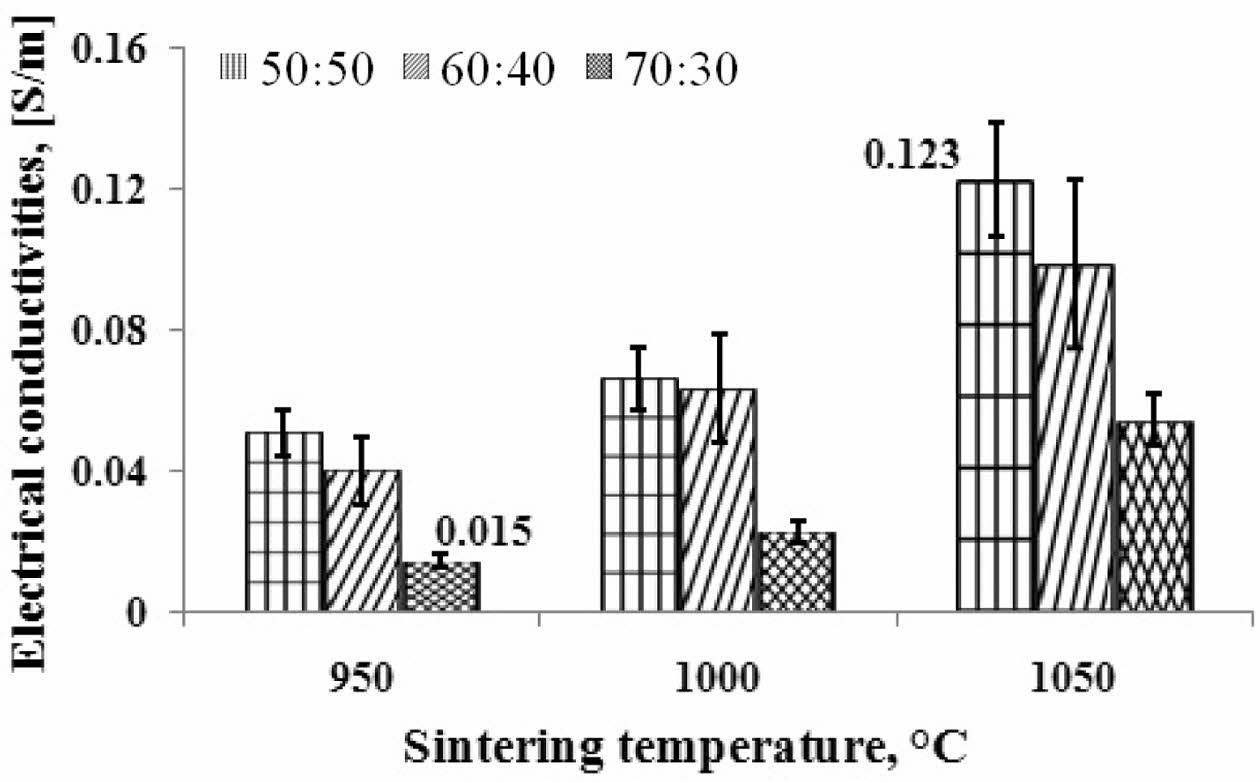
Based on current and voltage data, the electrical con- ductivity of ceramic carbon composites can be deter- mined. The results of calculations and analysis are shown in Fig. 5. The higher the temperature of pyrolysis sintering, the higher the electrical current delivery power. The higher the volume of carbon weight, the higher the electrical conductivity. This fact shows that the volume content of carbon weight can conduct electric current. Composites' highest electrical conductivity value is indicated by pyrolysis sintering at 1050 oC, at a composition ratio of 50:50% weight, i.e., 0.123 [S/m]. The lowest electrical conductivity value is indicated by a carbon-ceramic composite with a composition ratio of 70:30% weight, at a pyrolysis sintering temperature of 950 oC, with a value of 0.015 [S/m]. Ceramic carbon resistors (CCR) are used in this application as high voltage circuit breakers. The ceramic carbon composite (CCC) used as a CCR consists of an insulating matrix (ceramic) and electrically delivering carbon. The con- ductivity of a composite depends on the number of carbon phases present in the composite [21].
The relationship between electrical conductivities and porosities
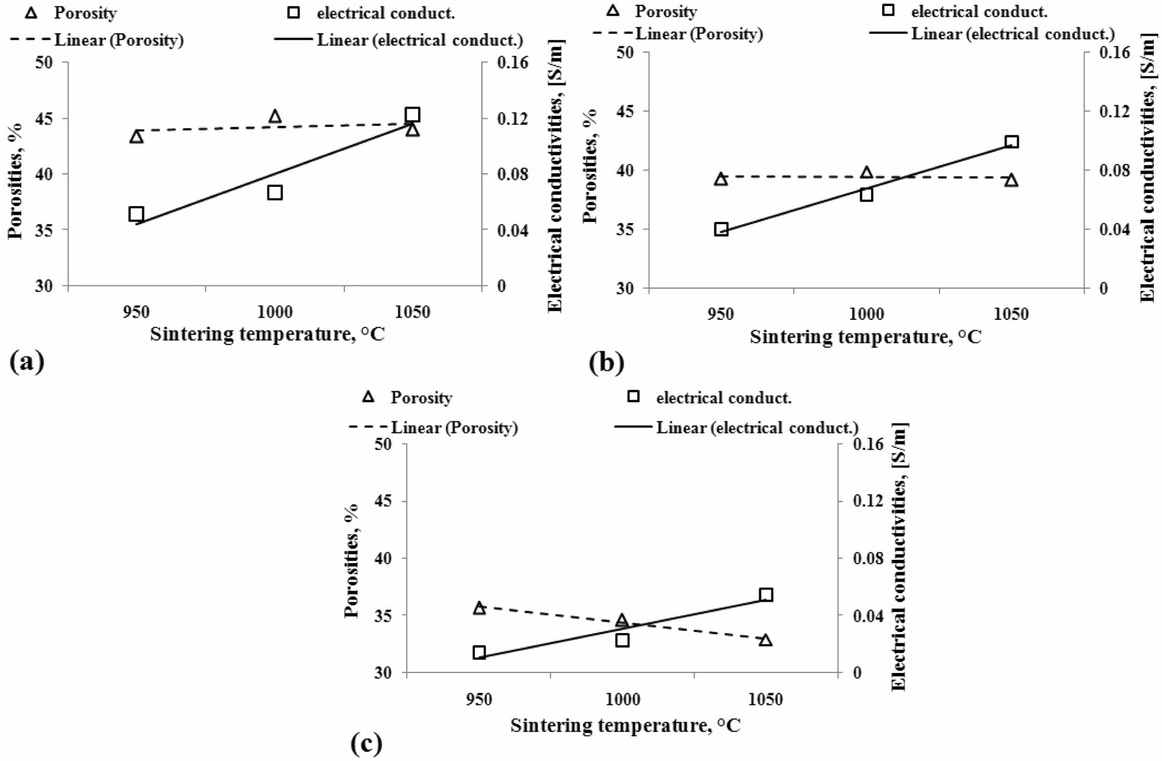
Discussion of the relationship between electrical conductivity and composite porosity in this study will only explain the phenomena and tendencies in both variables. Porosity is the form of cavities or spaces that separate the relationships between particles or elements from carbon-ceramic composites, and thus this condition will affect the delivery power of electric current or electrical conductivity. The discussion is shown in Fig. 6. In general, the increase in temperature in the sintering process influences the increase in the electrical con- ductivity of composites. However, when associated with the percentage of composite porosity, the results of this study can be said that porosity does not affect electrical conductivity significantly. Because, although porosity at values tends to be stable at relatively equal per- centages, electrical conductivity nevertheless increases with increased sintering temperature, mainly shown in Figs. 6(a) and (b), with carbon weight volume content of 50% and 40% wt. Meanwhile, the effect of tempera- ture sintering on porosity and electrical conductivity shows opposite tendencies in Fig. 6(c). In the image, when porosity decreases, electrical conductivity increases with increased sintering temperature.
The morphology of the carbon-ceramic composite
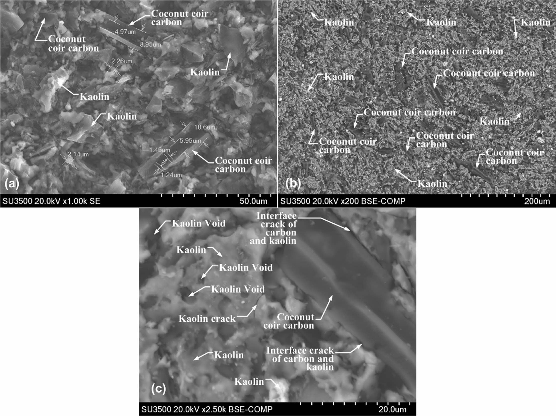
The morphology of the powder of the carbon-ceramic composite processed pyrolysis sintering was observed using the microscopic scanning electron Hitachi SU 3500, to characterize the kaolin and carbon particles contained and porous cavities in the composite that have been sintered. This technique is already commonly done by other studies to look at microstructures as done in this study [2, 24]. Epoxy/carbon composite morphology was observed with SEM [22]. In addition to quantity, specific properties of this transition also depend on the morphology and distribution of conductive phases, particularly on the interfaces of impurities and matrix interfaces [25]. Surface morphology and cross-section of MF supports and membranes treated at a temperature of 1150 oC are observed by SEM images [17]. Fig. 7(a), with a magnification of 1000 times, shows the difference in the geometric shape of the synthetic carbon of coconut coir. A shape with a brighter, smoother surface indicates the kaolin matrix of the kaolin-carbon composite. The small, dark-coloured features indicate the cavity or porous of this composite. Meanwhile, the elongated shape and seemingly parallel grooves indicate that this is coconut coir carbon fibre.
The distribution does not appear evenly, and this happens because the geometric shape of coconut coir carbon fibre is relatively irregular, both in shape and size, as shown in Fig. 7(b). Dark grey colour with an elongated groove shape that appears parallel indicates coconut coir carbon. Lighter grey and irregularly shaped colours such as curly hair indicate kaolin matrix, small dark black features indicating porous contained in the composite bulk. Features of interface cracks, matrix cracks and carbon filler cracks are shown in Fig. 7(c). The shape of the coconut coir carbon is very clearly indicated by an elongated rough shape and grooves that appear parallel, with a dark grey colour. Features with a surface that appears flat and smooth indicate a kaolin matrix with dark black porous holes. The long black line between kaolin features and carbon powder shows a crack in the interface between the kaolin matrix and the carbon powder. The micro-features contained in the composite bulk show porosity and cracks, and discon- nection of connectivity between the filler carbon powder. Such conditions weakened the electrical current delivery power in the composite bulk in this study.
Elements of kaolin-carbon ceramic
The study also investigated the elemental content in kaolin-carbon ceramics.
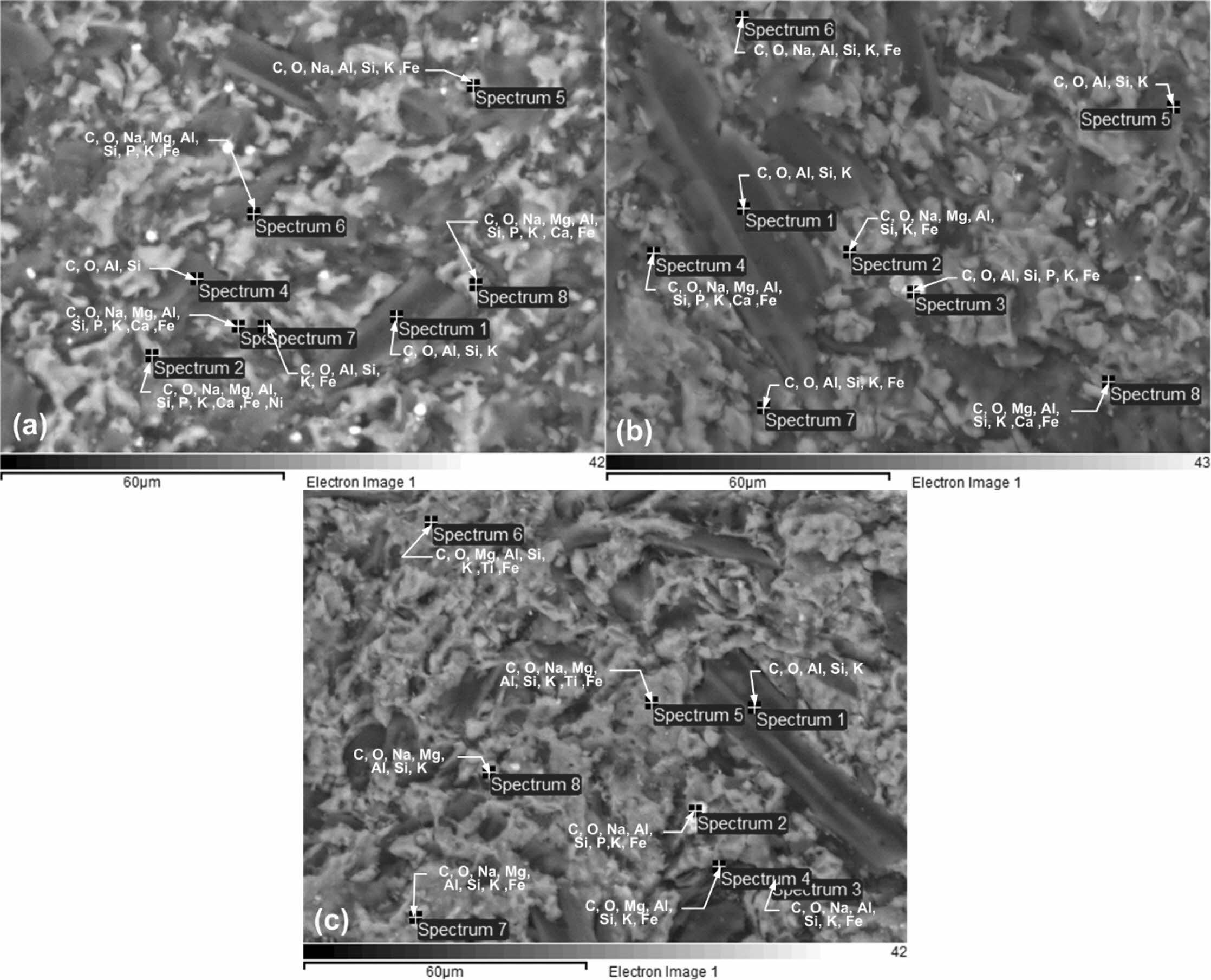
The research was conducted with SEM-EDS, a micro- scopic scanning electron Hitachi SU 3500. Investigations were conducted on kaolin-carbon specimens at all com- position ratios and on pyrolysis sintering of 1050 oC. Each specimen was investigated with eight spectrum points at random, on features considered unique. The observations of the features are shown in Fig. 8.
Fig. 8(a) shows the spectrum of observations on kaolin-carbon ceramics with a composition ratio of 50:50% wt. Each spectrum point shows the presence of the element carbon as the element with the highest percentage, followed by the oxygen element as the second largest element after carbon. The carbon element in this composition ratio is estimated at 57.78% wt, and the oxygen element is 24.04% wt. Other elements in kaolin-carbon ceramics include Si, Fe, Al, Na, K, Mg, P, Ca, and Ni. The percentage of the weight of the element is shown in Table 5.
Kaolin-carbon ceramics with a composition ratio of 60:40% wt show a carbon element content of 53.65% wt, and oxygen elements of 22.84% wt. All observation spectrum points show the content of the carbon element as the main element, as shown in Fig. 8(b). The content of other elements is relatively like that shown in Fig. 8(a), as shown in Table 5. Fig. 8(c) shows the same character, carbon element as the dominant element in kaolin-carbon ceramics with a composition ratio of 70:30% wt. The carbon element content in this com- position ratio is 31.99% wt, and 35.46% wt of the oxygen element. Other elements with different percentages are shown in Table 5. The highest carbon elements are in- dicated by a composition ratio of 50:50, then sequentially followed by composition ratios of 60:40, and 70:30. These facts can be considered as representing the carbon content in ceramics. In contrast, the highest Si content is indicated by a composition ratio of 70:30 with the element Si 10.85% wt, the composition ratio of 60:40 with the element Si 7.5% wt, and the composition ratio of 50:50 indicating the element Si 6.34% wt. The percentage sequence can be considered as representing the kaolin content in ceramic specimens in this study.
|
Fig. 2 Densities vs sintering temperature vs composition ratio |
|
Fig. 3 Porosities vs sintering temperature vs composition ratio. |
|
Fig. 4 Voltage - ampere relationship |
|
Fig. 5 The sintering temperature vs electrical conductivities. |
|
Fig. 6 The relationship between electrical conductivities and porosities. |
|
Fig. 7 Kaolin-carbon composite morfology |
|
Fig. 8 Elements of kaolin-carbon ceramic. |
The higher volume content of carbon weight makes carbon ceramic composites lighter. Density values due to the increase in sintering temperature are relatively the same and stable at adjacent values. The increase in pyrolysis sintering temperature does not change porosity significantly; porosity that occurs in carbon-ceramic composites at each composition ratio tends to be stable at adjacent values. The higher the sintering temperature, the higher the electric current that can flow in carbon ceramics. The higher the volume of kaolin, the lower the electric current that can flow. This condition is normal because kaolin (ceramic) is an insulator. The higher the volume of carbon weight, the higher the electrical conductivity. This fact shows that the volume content of carbon weight can conduct electric current. Although porosity is at a value that tends to be stable at a relatively similar percentage, electrical conductivity increases along with the increase in sintering temperature. The micro-features contained in the composite bulk show porosity and cracks, and disconnection of connectivity between the filler carbon powder.
Scheme of Leading Research of Product Innovation of DIPA of Politeknik Negeri Jakarta has funded this research, Contract Number: B.265/PL3.B/PN.00.03/2021, dated July 7, 2021. The author would like to thank UP2M, Politeknik Negeri Jakarta.
- 1. D.O. Obada, D. Dodoo-Arhin, M. Dauda, F.O. Anaf, A.S. Ahmed, O.A. Ajayi, Appl. Clay Sci. 150 (2017) 175-183.
-

- 2. H. Katsuki, S. Hirata, M. Inada, C.-S. Choi, J.-H. Park, J.-H. Lee, U.-S. Kim, K.-S. Han, J.-H. Kim, W.-S. Cho, and K.-T. Hwang, J. Asian Ceram. Soc. 8 (2020) 492-501.
-

- 3. R.L. Menchavez, M. Fuji, T. Shirai, and T. Kumazawa, J. Eur. Ceram. Soc. 34 (2014) 717-729.
-

- 4. B. Basnet, H.M. Lim, K.S. Lee, and I.J. Kim, J. Korean Ceram. Soc. 56 (2019) 513-520.
-

- 5. J.Y. Kim and K.T. Hwang, J. Korean Ceram. Soc. 56 (2019) 566-576.
-

- 6. V. Mymrin, C.F.G. Santos, K. Alekseev, M.A. Avanci, M.A. Kreusch, T. Borga, O. Graupmann, F.L. Cavalin, R.A. Monteiro, V.A. Ruy. Appl. Clay Sci. 155 (2018) 95-102.
-

- 7. M.M. Bazin, N. Ahmad, and Y. Nakamura, J. Asian Ceram. Soc. 7 (2019) 417-425.
-

- 8. H.P.A. Alves, J.B. Silva, L.F.A. Campos, S.M. Torres, R.P.S. Dutra, and D.A. Macedo. Ceram. Int. 42 (2016) 19086-19090.
-

- 9. Z. Hou, B. Cui, L. Liu, and Q. Liu, Ceram. Int. 42 (2016) 17254-17258.
-

- 10. B. Lin, S. Li, X. Hou, and H. Li, J. Alloys Compd. 623 (2015) 359-361.
-

- 11. A.E. Pramono, R. S. Mulyono, R.G. Sudarmawan, M.Z. Nura, H. Rahman, and N. Indayaningsih, J. Ceram. Process. Res. 21 (2020) 465-478.
-

- 12. J. Ondruška, Š. Csákia, V. Trnovcová, I. Štubňa, F. Lukáčb, J. Pokorný, L. Vozár, and P. Dobroň. Appl. Clay Sci. 154 (2018) 36-42.
-

- 13. H.I. Riyap, C.N. Bewa, C. Banenzoué, H.K. Tchakouté, C.H. Rüscher, E. Kamseu, M.C. Bignozzi, and C. Leonelli, J. Asian Ceram. Soc. 7 (2019) 199-212.
-

- 14. S. Boussen, D. Sghaier, F. Chaabani, B. Jamoussi, and A. Bennour, Appl. Clay Sci. 123 (2016) 210-221
-

- 15. H.P.S. Abdul Khalil, M. Jawaid, P. Firoozian, M. Amjad, E. Zainudin, and M.T. Paridah. Int. J. Polym. Anal. Charact. 18 (2013) 329-338.
-

- 16. X. Liu, X. Liu, and Y. Hu, Clay Miner. 50 (2015)199-209.
-

- 17. B. Jafari, M. Abbasi, S.A. Hashemifard, and M. Sillanpää, J. Asian Ceram. Soc. 8 (2020) 848-861.
-

- 18. D.O. Obada, D. Dodoo-Arhin, M. Dauda, F.O. Anafia, A.S. Ahmed, O.A. Ajayic, S. Csakid, N.D. Bansod, I.I. Kirima, and O.J. Momoh. Appl. Clay Sci. 194 (2020)105698.
-

- 19. W.M.L. Misrar, L. Saadi, M. Mansori, M. Waqif, and C. Favotto, J. Asian Ceram. Soc. 5 (2017) 199-208.
-

- 20. S.K. Hubadillah, Z. Harun, M.H.D. Othman, A.F. Ismail, and P. Gani, J. Asian Ceram. Soc. 4 (2016) 164-177.
-

- 21. R. Kumar and P. Bhargava, J. Asian Ceram. Soc. 3 (2015) 262-265.
-

- 22. P. Charoeythornkhajhornchai and C. Samthong, J. Mater. Res. 35 (2020) 1874-1887.
-

- 23. R. Kumar and P. Bhargava, J. Asian Ceram. Soc. 5 (2017) 304-312.
-

- 24. B. Onwona-Agyeman, N. Lyczko, D.P. Minh, A. Nzihou, and A. Yaya, J. Ceram. Process. Res. 21 (2020) 35-41.
-

- 25. P. Hvizdoš and A. Vencl, Encycl. Mater. Compos. (2021) 116-133.
-

 This Article
-
2022; 23(2): 171-180
Published on Apr 30, 2022
- 10.36410/jcpr.2022.23.2.171
- Received on Sep 15, 2021
- Revised on Dec 26, 2021
- Accepted on Jan 10, 2022
 Services
- Abstract
introduction
experiment
result and discussion
conclusion
- Acknowledgements
- References
- Full Text PDF
Shared
 Correspondence to
- Agus Edy Pramono
-
Department of Mechanical Engineering, Politeknik Negeri Jakarta, Jln. Prof. Dr. G.A. Siwabessy, Kampus UI. Depok 16425, West Java, Indonesia
Tel : +62 21 7863530 Fax: +62 21 7863530 - E-mail: agus.edypramono@mesin.pnj.ac.id



 Copyright 2019 International Orgranization for Ceramic Processing. All rights reserved.