- Bending strength and wear characteristics of Si3N4 composites containing additives SiO2 and TiO2
Seok-Hwan Ahna and Ki-Woo Namb,*
aDepartment of Aero Mechanical Engineering, Jungwon University, Chungbuk 28024, Korea
bDepartment of Materials Science and Engineering, Pukyong National University, Busan 48547, KoreaThis article is an open access article distributed under the terms of the Creative Commons Attribution Non-Commercial License (http://creativecommons.org/licenses/by-nc/4.0) which permits unrestricted non-commercial use, distribution, and reproduction in any medium, provided the original work is properly cited.
Cracking in ceramics poses a serious threat to the safety of components. In the study of crack healing, SiO2 was the healing material. In this study, TiO2 was added to improve the strength of ceramics, and SiO2 was added or coated to heal cracking. These show effectiveness by heat treatment. The bending strength increased by adding TiO2 and SiO2, and the friction coefficient and wear loss were smaller than that of the non-addition
Keywords: Wear, Friction coefficient, Wear loss, Additives, Strength
While ceramic is a material that shows high hardness, and excellent corrosion resistance and abrasion resistance, it has low fracture toughness, being easy to fracture by even micro crack. Micro cracking occurs on the surface of components during processing or operating. Such micro cracks rapidly reduce the reliability and strength of ceramic components.
A crack healing method has been proposed as one of the micro crack control methods [1], and many researchers have published results [2-9]. Crack healing is a principle that heals cracking by forming SiO2 by chemical reaction between the Si and O of SiC or Si3N4 [10-14]. Oxygen (O2) is necessary for crack healing, and crack healing occurs only on the surface in contact with O2. Thus, an embedded crack cannot be healed. Many researchers have found the oxide SiO2 to be a crack healing substance. In previous study, the authors [15] evaluated the crack healing and bending strength properties by adding the crack healing substance SiO2 to the synthesis of ceramic powder. In this study [15], 1.3 wt.% SiO2 colloid was optimal. The authors also investigated the crack healing characteristics of SiC with the number of SiO2 colloid coatings [11,16]. The coating method (hydrostatic pressure coating or roll coating) had no effect on crack healing, and if the coats exceeded the critical coating number, cracks no longer healed. Crack width of less than 1.4 mm could be healed regardless of crack length [17]. The SiO2 formed on the surface by heat treatment healed the crack, and increased the strength, due to the strengthen- ing by sintering. Tavangarian et al. [18] classified various ceramics and composites according to their healing mechanism, i.e., oxidation, diffusion, and phase trans- formation. Yang et al. [19] studied the crack healing of Ti2AlC. In the crack healing of Ti2AlC, discontinuous coarse TiO2 grains diffused outward, and a continuous Al2O3 protective outer layer formed, decreasing cavities. However, not many studies have reported the wear characteristics of ceramics with crack healing properties.
In this study, Si3N4/SiC composites with additives SiO2 and TiO2 were coated with SiO2 colloid to evaluate the bending strength and wear characteristics according to the heat treatment temperature.
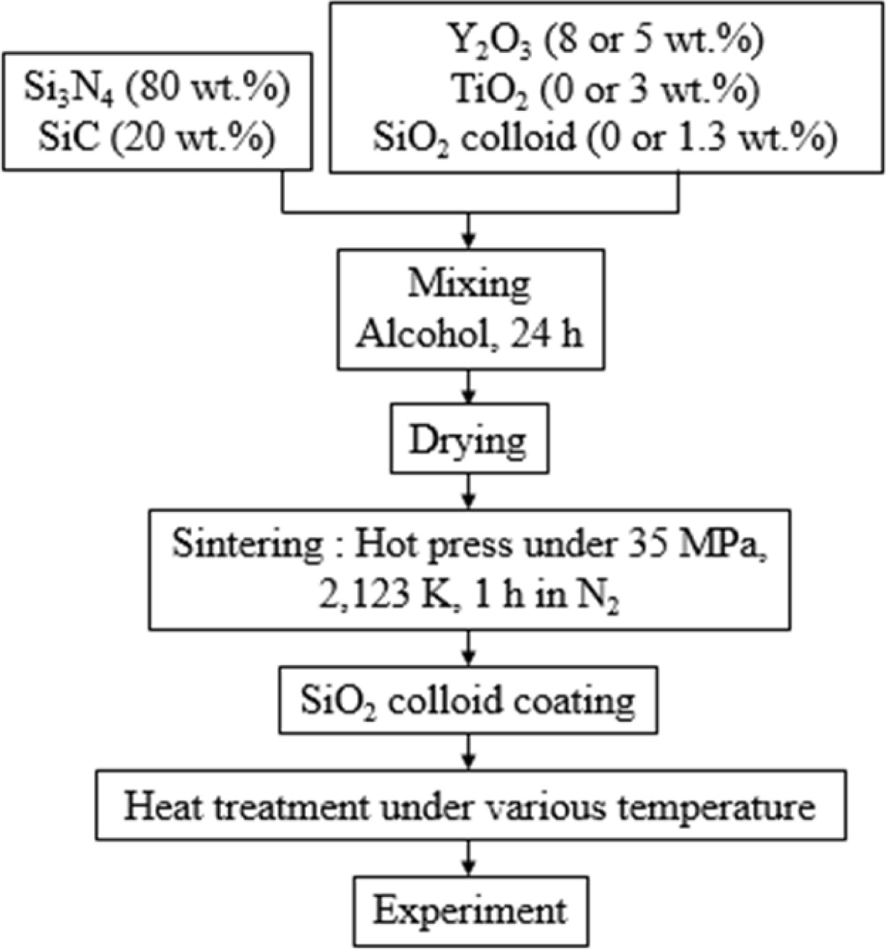
The Si3N4 powder used in this study has an average size of 0.2 μm, and the SiC powder has an average size of 0.27 μm. The sintering aid used Y2O3 (average size of 33 nm), commercially available anatase type TiO2, and 12 wt.% SiO2 colloid. SiO2 colloid was added or coated, to evaluate the crack healing and wear properties. Table 1 shows the compositions of each specimen.
The powder was mixed with Si3N4 balls and alcohol for 24 h. Sintering was carried out under 35 MPa pressure of N2 gas atmosphere at 1,850 oC for 1 hour. Specimens were mirror polished to 3 mm × 4 mm × 18 mm (for bending test) and 3 mm × 4 mm × 10 mm (for wear test). A crack of about 100 mm length was made in the center of the specimen surface, using a Vickers hardness tester. The crack specimen was coated with SiO2 colloid, and heat treated for 1 h in air at (700-1,300) oC. Bending strength was evaluated by three-point bending test with a crosshead speed of 0.5 mm/min. The type of test machine was “block on ring”. The counterpart of the wear specimen was QT vacuum heat-treated SKD11, diameter of 35 mm, and thickness of 7 mm. Wear test conditions were the rotation number of 50, applied load of 9.8 N, and 500 m of wear distance. Five pieces of crack-healed specimens were used under each condition. Fig. 1 shows the sintering process.
|
Fig. 1 Flow chart of sintering. |
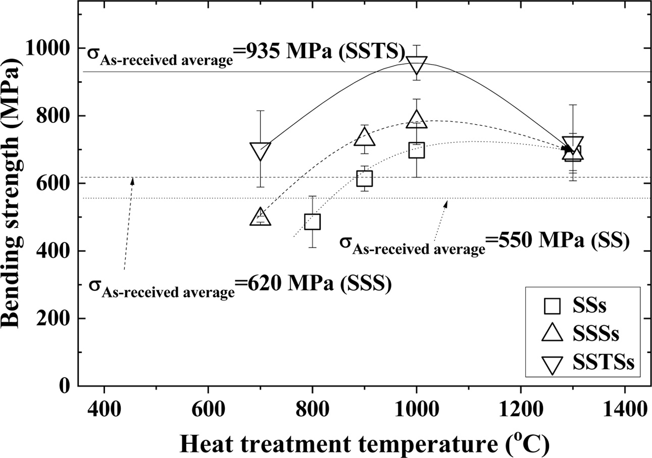
Fig. 2 shows the relationship between the heat treatment temperature and the bending strength. In this figure, SiO2 colloid non-coated as-received specimens are called SS, SSS and SSTS, respectively, and SiO2 colloid coated crack specimens are called SSs, SSSs and SSTSs, respectively. Where, square (□) indicates the SSs specimen, triangle (△) indicates the SSSs specimen, and inverted triangle (∇) indicates the SSTSs specimen. The average bending strength of SiO2 colloid non-coated as-received specimens were (550, 620, and 935) MPa for SS specimen, SSS specimen, and SSTS specimen, respectively. The bending strength of SSS with additive SiO2 colloid increased about 13 % compared to SS, but that of SSTS with additive TiO2 increased about 50% compared to SSS [20]. Ti ions diffused outwards during oxidation, and cavities decreased [19]. The healing substances SiO2 further improved the sinterability [21, 22]. The three types of crack specimens with SiO2 colloid coating showed the highest strength at heat treatment temperature of 1,000 oC [23]. At this time, the bending strength was in the order: SSTSs > SSSs > SSs. The bending strength of SSTSs specimens at 1,000 oC was about 1.37 times that of SSs, and about 1.22 times that of SSSs. The bending strength of (700-900) oC was small, since the crack did not heal com- pletely [24]. The bending strength of 1,300 oC was reduced, because it rather formed a crack in the healed part by the high temperature [25]. Overall, the bending strength of crack specimens with SiO2 colloid coating was in the order: SSTSs > SSSs > SSs, as with the as-received specimens.
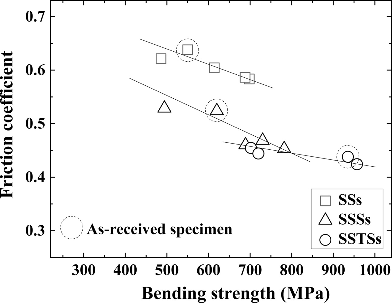
Fig. 3 shows the relationship between bending strength and friction coefficient. Dotted circles represent the as-received specimen. The friction coefficient was propor- tional to the bending strength. That is, the friction coefficient decreased as the bending strength increased. Jianxin’s study of SiC whisker composites found the reduced coefficient of friction in accordance with increase or decrease of the whisker content [24]. The friction coefficient of the as-received specimen showed the same tendency as the bending strength of Fig. 2. The friction coefficient was in the order: SSs > SSSs > SSTSs.
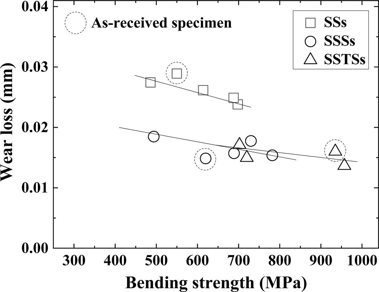
Fig. 4 shows the relationship between bending strength and wear loss. The wear loss was proportional to the bending strength. That is, the wear loss decreased as the strength increased [26]. The wear loss of the as-received specimen showed the same tendency as the bending strength of Fig. 2. The wear loss of SSTSs specimen with additive TiO2 was smaller than that of the SSs and SSSs specimens. However, although the wear loss of SSSs and SSTS specimens decreased linearly, the wear loss of SSTSs specimens with additive TiO2 was slightly smaller than that of SSSs specimen.
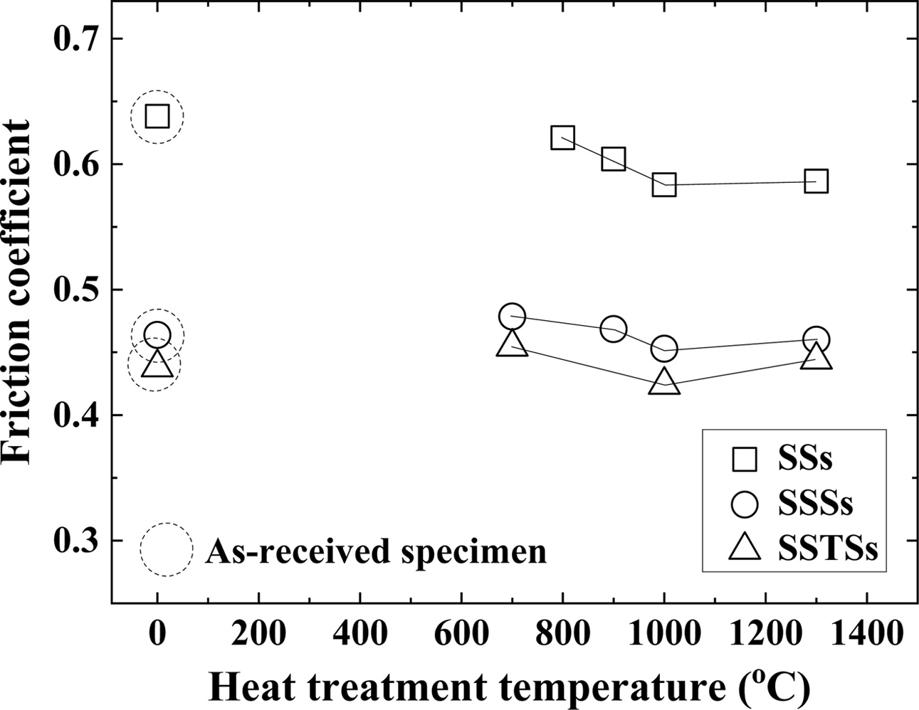
Fig. 5 shows the coefficient of friction depending on the heat treatment temperature. The coefficient of friction showed the same tendency as the bending strength of Fig. 2. In other words, the three types of specimens showed the smallest friction coefficient at 1,000 oC. The friction coefficient of (700-900) oC was larger than that of 1,000 oC, and the friction coefficient of 1,300 oC was slightly larger than that of 1,000 oC. Vashishta studied the effect of heat treatment tempera- ture of (300-950) oC on the abrasive behavior of WC-12Co and Cr3C2-25NiCr coatings. In that study, the friction coefficient increased after decreasing until 750 oC [27]. The friction coefficient of the as-received specimens was similar to that of 800 oC or less. The heat treatment temperature of 800 oC or less means that there is no effect on the crack healing and strengthening with respect to the ceramic of the present study. The coefficient of friction is in the order: SSs > SSSs > SSTSs, and in reverse order to the bending strength.
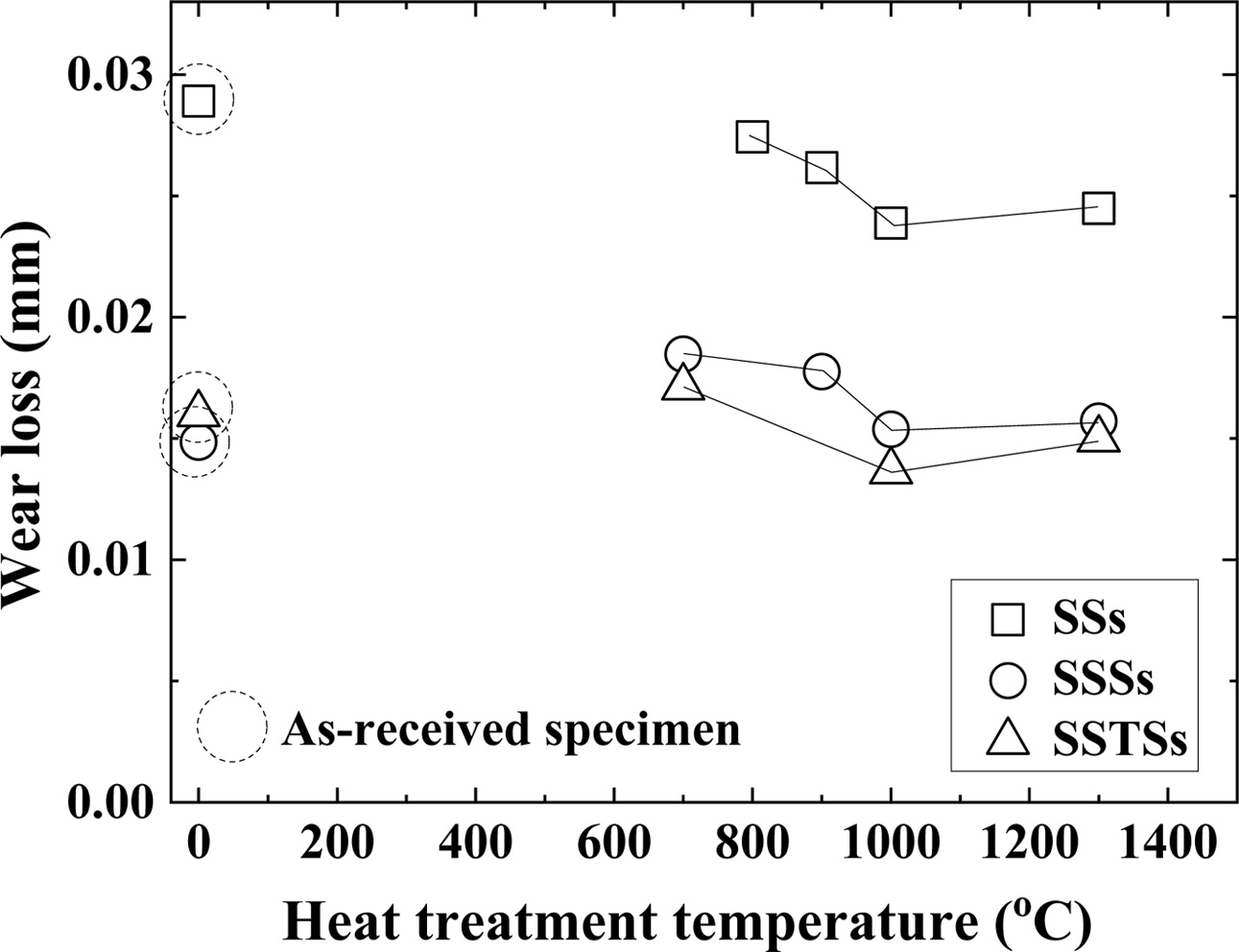
Fig. 6 shows the wear loss according to the heat treatment temperature. The wear loss showed the same tendency as the bending strength of Fig. 2. In other words, the three types of specimens showed the smallest wear loss at 1,000 oC. The wear loss of (700-900) oC was larger than that of 1,000 oC, and the wear loss of 1,300 oC was also slightly larger than that of 1,000 oC. The wear loss of the as-received specimens showed similar tendency to the friction coefficient at low tem- perature. For the ceramics of this study, low-temperature heat treatment means no effect on the crack healing and strengthening.
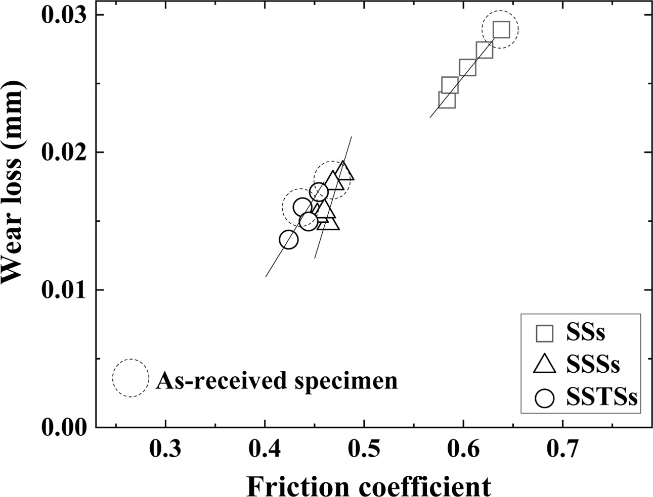
Fig. 7 shows the relationship between the friction coefficient and the wear loss. The friction coefficient and wear loss were proportional to each other. Wear loss was increased as the friction coefficient increased. The wear loss and friction coefficient of the SSs specimen was the greatest. The wear loss of the SSSs and SSTS specimens was similar, but the wear loss of the SSTS specimens was a little smaller. This is because the cavity was reduced by the additive TiO2, and the strength was increased by the additive SiO2 colloid. However, the difference between the as-received specimens and the SiO2 colloid coated specimens could not be specified.
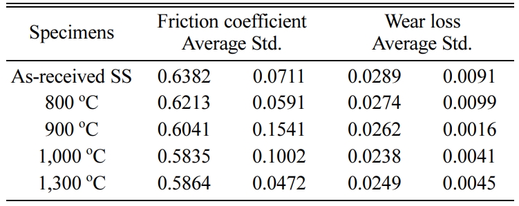
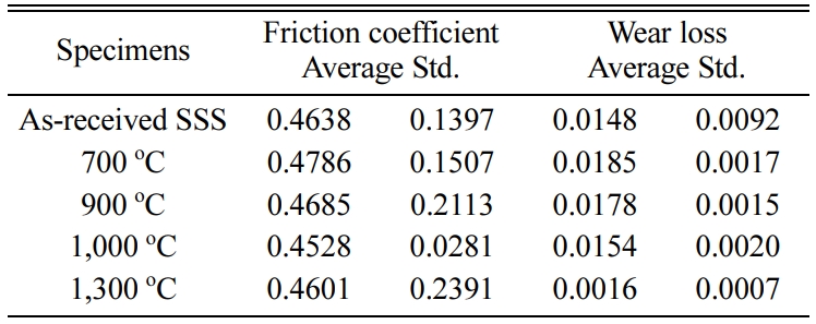
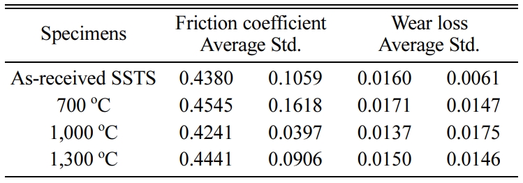
Tables 2-4 3 show the average of the friction coefficient, wear loss, and standard deviation (Std) of the SSs, SSSs, and SSTSs specimens in different heat treatment temperature. Here, SS, SSS, and SSTS are the as-received specimens, without the SiO2 colloid coating.
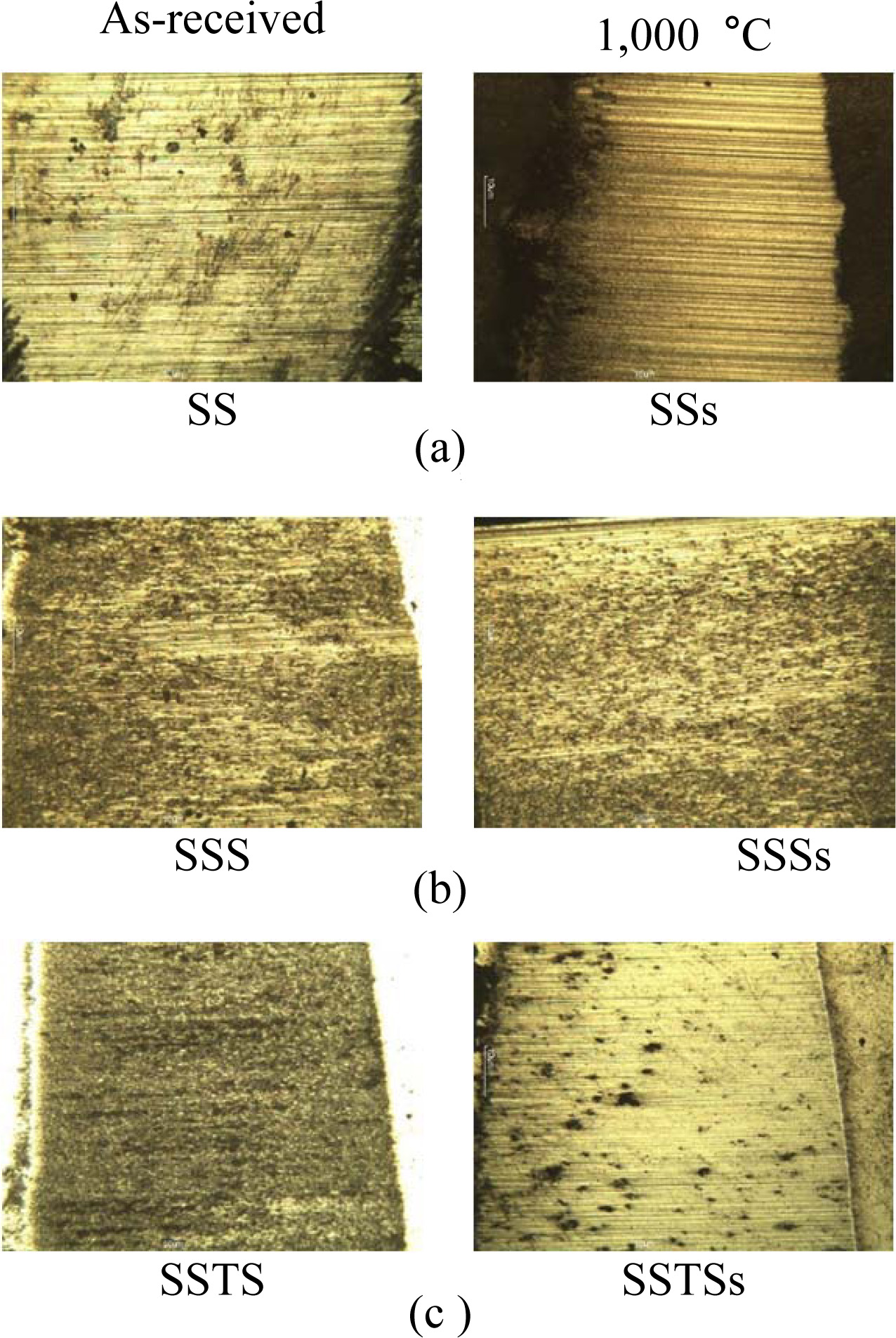
Fig. 8 shows the wear surfaces of the as-received specimens and the heat-treated specimens (1,000 oC) after wear test. The wear surface showed a striped shape, regardless of the specimen type. This striped pattern is abrasive wear behavior. Abrasive wear accounts for 50% of the loss due to wear. Abrasive wear is made by the much remaining debris between the two substances during operating. The dark part of the specimen is oxidative wear, which forms an oxide film by sliding action with the counterpart (SKD11) [28]. The wear surface was a little different, depending on the strength of the specimen. In Fig. 8(a), the stripe of the wear surface was the clearest, but in Figs. 8(b) and (c), the stripes were dim compared with Fig. 8(a), due to the increase of bending strength.
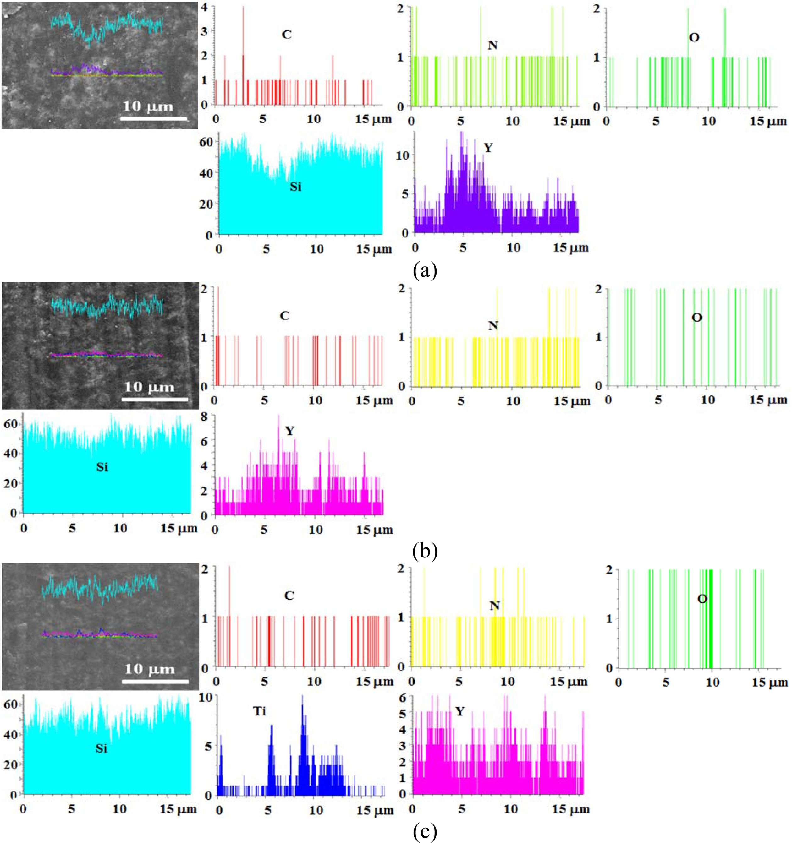
Fig. 9 shows the line profile of the heat-treated specimen at 1,000 oC. (a), (b), and (c) are the SSs specimen, SSSs specimen, and SSTSs specimen, respectively. Each synthesized component of these specimens with SiO2 colloid coating was detected. The component had the most Si in proportion to the synthesis ratio, and Y and Ti were detected in order. The line profile could not specify the amount of each synthetic component.
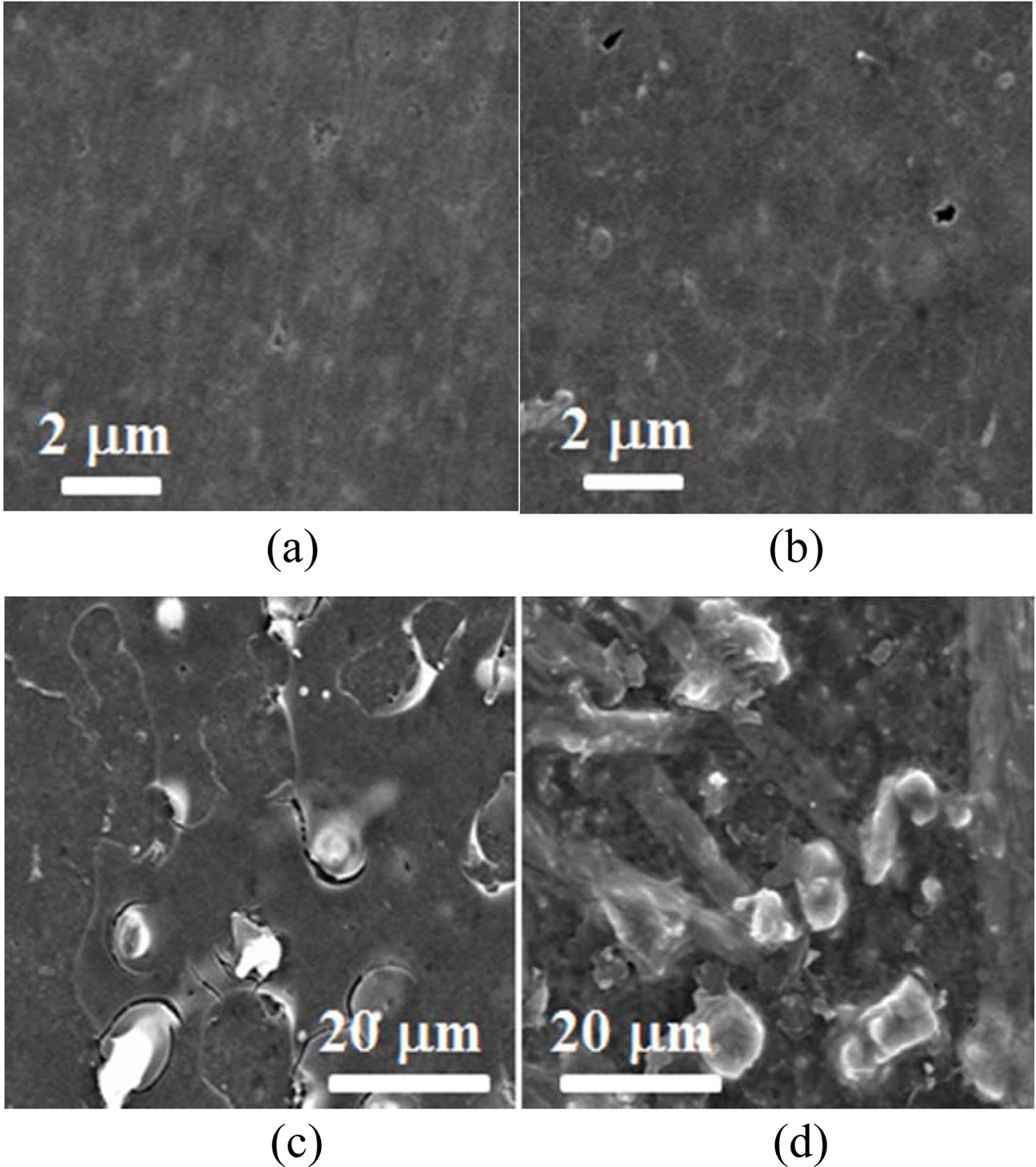
Fig. 10 show the surface morphology according to heat treatment in specimen with/without SiO2 colloid coating. Fig. 10(a) is an as-received specimen, Fig. 10(b) is a heat treated specimen at 900 oC, and (c) and (g) are heat treated specimens at 900 oC and 1,300 oC with SiO2 colloid coating, respectively. Surface defect such as pore was observed in mirror-polished as-received specimen (a). The heat treated specimen (b) at 900 oC without SiO2 colloid coating was almost similar to the as-received specimen (a), and surface defect was observed. The heat treated specimen (c) at 900 oC with SiO2 colloid coating was observed that the SiO2 crystals are covered on the surface. On the other hand, the heat treated specimen (d) at 1,300 oC with SiO2 colloid coating showed large SiO2 crystals.
The heat treatment reaction of Si3N4/SiC composite ceramic is as follows [29, 30].

Where, Y2Si2O7 and Y2Ti2O7 are crystal phases, and anatase-type TiO2 becomes a rutile-type crystal phase at 500 oC or more. SiO2 has a glass phase and a crystal phase, and the amount of the SiO2 crystal phase depends on the heat treatment temperature. In the ceramics containing Si, glass phase SiO2 contributes to the strength recovery, and the strength increases. In addition, SiO2 formed on the surface is decreased the friction coefficient and wear loss by lubrication action
|
Fig. 2 Heat treatment temperature dependence of the bending strength in accordance with SiO2 colloid coating. |
|
Fig. 3 Relationship between bending strength and friction coefficient. |
|
Fig. 4 Relationship between bending strength and wear loss. |
|
Fig. 5 Relationship between friction coefficient and heat treatment temperature. |
|
Fig. 6 Relationship between wear loss and heat treatment temperature. |
|
Fig. 7 Relationship between wear loss and friction coefficient. |
|
Fig. 8 Wear surfaces obtained from as-received specimens and 1,000 oC specimens: (a) SS and SSs specimens, (b) SSS and SSSs specimens, (c) SSTS and SSTSs specimens. |
|
Fig. 9 Line profile obtained from 1,000 oC specimens: (a) SSs specimen, (b) SSSs specimen, (c) SSTSs specimen. |
|
Fig. 10 The surface morphology according to heat treatment in specimen with/without SiO2 colloid coating. (a) As-received specimen, (b) Heat treated specimen at 900 oC, (c) Heat treated specimen at 900 oC with SiO2 colloid coating, (d) Heat treated specimen at 1,300 oC with SiO2 colloid coating |
|
Table 2 Friction coefficient and wear loss of SSs specimen in different heat treatment temperature. |
|
Table 3 Friction coefficient and wear loss of SSSs specimen in different heat treatment temperature. |
|
Table 4 Friction coefficient and wear loss of SSTSs specimen in different heat treatment temperature. |
This study evaluated the bending strength and wear characteristics according to the heat treatment temper- ature of three types of Si3N4/SiC ceramics with SiO2 colloid coating. The obtained results are as follows:
The bending strength of the three types of crack specimens with SiO2 colloid coating was higher than that of the uncoated specimens, and showed the highest bending strength at heat treatment temperature of 1,000 oC. The bending strength of SSTSs specimens at 1,000 oC was about 1.37 times that of SSs, and about 1.22 times that of SSSs.
Friction coefficient and wear loss were in the order: SSs > SSSs > SSTSs, and the relationship of both parameters was proportional to each other. They were also inversely proportional to the bending strength. The SiO2 colloid coating increased the strength, but had little effect on the wear behavior.
The wear surface showed abrasive wear regardless of the specimen type and heat treatment, and the line profile detected each synthesized component. However, the amount of each synthetic component could not be specified.
This work was supported by the Jungwon University Research Grant (2019_008).
- 1. F.F. Lange, J. Am. Ceram. Soc. 53[5] (1970) 290.
-

- 2. E.A. Gulbransen and S.A. Jansson, Oxid. Met. 4[3] (1972) 181-201.
-

- 3. J.J. Petrovic and L.A. Jacobson, J. Am. Ceram. Soc. 59[1–2] (1976) 34-37.
-

- 4. T.K. Gupta, J. Am. Ceram. Soc. 59[5-6] (1976) 259-262.
-

- 5. J. Korouš, M.C. Chu, M. Nakatani, and K. Ando, J. Am. Ceram. Soc. 83[11] (2000) 2788-2792.
-

- 6. T. Osada, W. Nakao, K. Takahashi, K. Ando, and S. Saito, J. Eur. Ceram. Soc. 27[10] (2007) 3261-3267.
-

- 7. K.H. Kang and J.D. Yun, J. Ceram. Process. Res. 12[5] (2011) 583-587.
- 8. Y.T. Kim, S.G. Kim, and J.W. Park, J. Ceram. Process. Res. 16[5] (2015) 624-628.
- 9. P.S. Lee, T.H. Ahn, S.H. Kim, H.M. Kim, and K.B. Shim, J. Ceram. Process. Res. 16[S1] (2015) 114-131.
- 10. Y.S. Jung, Y. Guo, W. Nakao, K. Takahashi, K. Ando, and S. Saito, Fatigue Fract. Engng. Mater. Struct. 31[1] (2008) 2-11.
-

- 11. K.W. Nam, H.R. Jeong, J.W. Kim, and S.H Ahn, J. Ceram. Process. Res. 17[11] (2016) 1188-1191.
- 12. K.H. Lee, K.W. Nam, and S.H. Ahn, J. Ceram. Process. Res. 18[12] (2017) 831-842.
- 13. H.S. Nam, J. Ceram. Process. Res. 20[4] (2019) 379-387.
- 14. J.W. Lee, K.W. Nam, and W. Nakao, J. Ceram. Process. Res. 21[2] (2020) 200-207.
-

- 15. K.W. Nam, S.W. Park, J.Y. Do, and S.H. Ahn, Trans. of KSME, A 32[11] (2008) 957-962.
-

- 16. K.W. Nam, J. Powder Tech. 2013 (2013) 695895.
-

- 17. K.W. Nam and J.S. Kim, Mater. Sci. Eng. A 527[13-14] (2010) 3236-3239.
-

- 18. F. Tavangarian, D. Hui, and G. Li, Engineering 144 (2018) 56-87.
-

- 19. H.J. Yang, Y.T. Pei, J.C. Rao, J.Th.M. De Hosson, S.B. Li, and G.M. Song, Scripta Materialia 65[2] (2011) 135-138.
-

- 20. K.W. Nam and J.R. Hwang, J. Mech. Sci. Tech. 26[7] (2011) 2093-2096.
-

- 21. K.W. Nam, M.K. Kim, S.W. Park, S.H. Ahn, and J.S. Kim (2007), Mater. Sci. Eng. A 471[1-2] (2007) 102-105.
-

- 22. K.W Nam, J.S. Kim, and S.W. Park, Int. J. Mod. Phys. B 24[15-16] (2010) 2869-2874.
-

- 23. K. Ando, K. Houjyou, M.C. Chu, S. Takeshita, K. Takahashi, S. Sakamoto, and S. Sato, J. Eur. Ceram. Soc. 22[8] (2002) 1339-1346.
-

- 24. K.W. Nam S.H. Park, and J.S. Kim, J. Ceram. Process. Res. 10[4] (2009) 497-501.
-

- 25. S.K. Lee, W. Ishida, S.Y. Lee, K.W. Nam, and K. Ando, J. Eur. Ceram. Soc. 25[5] (2005) 569-576.
-

- 26. D. Jianxin, Ceram. Int. 27[2] (2001) 135-141.
-

- 27. N. Vashishth, S.G. Sapate, P. Bagde, and A.B. Rathod, Tribol. Int. 118 (2018) 381-399.
-

- 28. K.J. Siczek, in “Tribological processes in the valve train systems with lightweight valves: New research and modelling” (Butterworth-Heinemann, 2016) pp. 85-180.
- 29. K.W. Nam and J.S. Kim, J. Ceram. Process. Res. 11[1] (2010) 20-24.
- 30. M.K. Kim, H.S. Kim, S.B. Kang, S.H. Ahn, and K.W. Nam, Solid State Phenomena. 124-126 (2007) 719-722.
-

 This Article
-
2021; 22(1): 54-60
Published on Feb 28, 2021
- 10.36410/jcpr.2021.22.1.54
- Received on Jun 26, 2020
- Revised on Jul 16, 2020
- Accepted on Aug 14, 2020
 Services
- Abstract
introduction
materials and experiment methods
results and discussion
conclusions
- Acknowledgements
- References
- Full Text PDF
Shared
 Correspondence to
- Ki-Woo Nam
-
Department of Materials Science and Engineering, Pukyong National University, Busan 48547, Korea
Tel : +82-51-629-6358 Fax: +82-51-629-6353 - E-mail: namkw@pknu.ac.kr


 Copyright 2019 International Orgranization for Ceramic Processing. All rights reserved.