- Quadratic magnetoelectric effect of barium titanate-cobalt ferrite (0-3) ceramic composite
Morad Etier* and Hesham Almomani
Industrial Engineering Department, The Hashemite University, Zarqa 13133, Jordan
In this research, the
quadratic magnetoelectric effect for different compositions of barium titanate
cobalt ferrite ceramic composites has been reported. Structural analysis was
firstly demonstrated using different techniques e.g. x-ray diffraction and scanning
electron microscopy, then both the first and the second order magnetoelectric
effects were measured and analyzed. It was shown that the magnetic,
ferroelectric and magnetoelectric properties of the ceramic composites depend
mainly on the weight percentage of the constituents. Sample of 50% weight of
barium titanate gave the highest longitudinal and traverse magnetostriction.
The maximum induced magnetization as a function of electric field was observed
for the sample contains 50% weight of barium titanate with a second order
magnetoelectric coupling coefficient value g333 = 20 × 10-18 s/V.
This value is considered to be the first estimated quadratic magnetoelectric
effect value for a composite material.
Keywords: Mutliferroics, Quadratic magnetoelectric effect, (0-3) Composite
Composites are interesting nowadays due to the new
properties resulting from the combination of two materials, i.e combination of
ferroelectric with ferro- magnetic
material to produce magnetoelectrics (MEs). These materials can be polarized by
magnetic field and magnetized by electric effect which correspond to the direct
and the converse magnetoelectric effect, respectively. Sensors,
MERAMs, transformers, energy harvesters and electric field tunable devices are the
main possible applications for the ME materials [1-5]. In single phase
magnetoelectric materials, the low values of the ME effect restrict their
technological applications. On the other hand, composites that combine
piezomagnetism and piezoelectricity still an adequate option for
optimizing the effect, because of the variety of
synthesizing methods, structures and properties. This may inspire
researchers for finding the optimum conditions in order to gain better results.
In theory, the direct and the converse magnetoelectric effect are obtained from
the derivative of the free energy (F) of a system with respect to both
electric and magnetic fields as follows [6]:
where P, M are the electric polarization and
the magnetization, respectively. H and E are the magnetic and the
electric fields, respectively, and μo is
the magnetic constant. The first order magnetoelectric effects (αij or αji [unit s/m]) are the
induced magnetization
by electric field M(E), or the induced polarization
by magnetic field P(H), respectively. In case of the second order
magnetoelectric effect (βijk [unit s/A] and γijk [unit s/V]) are the
change of dielectric permittivity with respect to magnetic field e (H) or the variation of
permeability by electric field μ(E)
[7]. Using equations (1) and (2), the second order ME effect γijk is
proportional to the square of the
applied electric field γ = (2μoΔM)/(ΔE)2 while βijk is proportional to
the square of the applied magnetic field β = (Δp)/(ΔH)2 . Utilizing these equations, the first one β is more clear in the converse
ME effect, because it depends on the applied electric field, while the second
one b appears in
the direct ME measurement because it depends on the applied magnetic field.
Both the first and the second order magnetoelectric effect can be detected
experimentally in the same material.
Previously, it was reported that the second order ME effect for single phase
materials was experimentally measured for lithium ferrite (LiFe5O8)
and Yttrium Iron Garnet YIG (Y3Fe5O12) in
the low-temperature interval 4-100K [8-10]. In composites, the magnetoelectric
effect depends on the linear piezoelectric effect of the first constituent
which is usually ferroelectric, and also on the nonlinear magnetostrictive
effect of the second one which is ferromagnetic. For that reason, one should
expect linear and nonlinear magnetoelectric effect obtained from the
combination of ferromagnetic/ferroelectric magnetoelectric
composites. Most of the magnetoelectric studies
for composites with piezomagnetic-piezoelectric phases are
carried out for the linear effect where the ac electric field or voltage is
measured as a function of ac magnetic field. Different connectivies
of magnetoelectrics have been synthesized and analyzed including the
(0-3), (1-3) and (2-2) structures [11-13]. These structures included, sintered
ceramic samples, epitaxial thick and thin films, pillars and others. The
interaction between the piezoelectrics and the piezomagnetics in such structures
is crucial factor to produce the magnetoelectric effect.
Among these structures, the (0-3) connectivity still a good option in order to
give isolated magnetic grains distributed inside a ferroelectric matrix. This
can provide more interaction areas between the phases, excellent poling and
accomplished strain mediated transfer capabilities. However,
different approaches were empolyed to synthesize (0-3)
composites including sol-gel and sintering technique, pulsed laser deposition
and epoxy bonding of layers. In literature, several materials were
selected to synthesize magnetoelectric composites, for
examples, PZT/NFO epitaxial heterostructure [14], CFO/BTO core shell structure
[15], PMN-PT/Terfenol-D plate [16], PZT-NFO-PZT thin films [17] and many
others. Barium titanate (BTO) and cobalt ferrite (CFO) have
excellent piezoelectric and piezomagnetic properties for the
application of electric and magnetic sensors, respectively.
For composites, the nonlinear magnetoelectic effect was
reported as a voltage coefficient quadratic effect βijk
which appeared in the direct magnetoelectric effect for
different materials [18-20]. To our knowledge the second order ME effect in
composites (γijk) is not reported for such systems nor for other
composites. In this article and for the first time, the values of the second
order of the ME effect γijk
for different composition of xBTO-(1-x)CFO system were measured and reported.
The values of the second order magnetoelectric effect are
detected for such systems based on the converse magnetolectric effect
experiment setup.
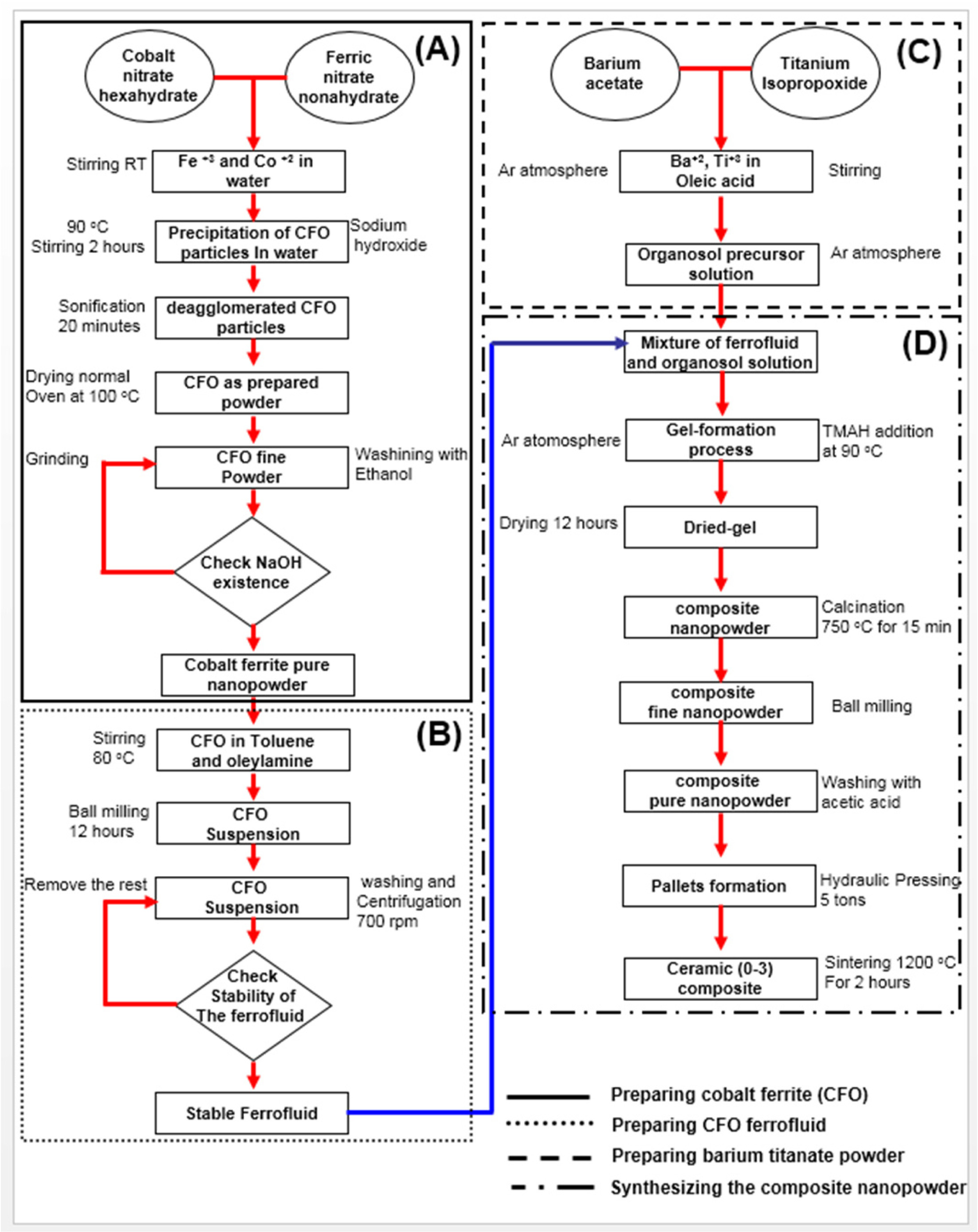
The detailed procedure for synthesizing the composites are
shown in Fig. 1. The co-precipitation method was used to synthesize cobalt iron
oxide nanoparticles using the same molar ratio of Fe(NO3)3·H2O
and Co(NO3)2·6H2O in water.
The precipitation of cobalt ferrite particles was started after the addition of
sodium hydroxide at 90 oC. The detailed sequence is shown in flowchart
(A) in Fig. 1. Several times of ethanol washing can remove
the rest of sodium hydroxide which may remain in the solution. The powder was
sonificated for 20 min to reduce the particles' agglomeration then dried
at 100 oC for 2 h. Inside an argon atmosphere, barium
titanate precursor solution was prepared using barium acetate Ba(C2H3O2)2
and titanium isopropoxide TiC12H28O4
in oleic acid (flowchart C in Fig. 1). An organosol precursor
was formed where ions of titanium and barium are dissolved in oleic acid under
magnetic stirring. Flowchart (B) in Fig. 1 shows the procedure for preparing
cobalt ferrite stable ferrofluid, where the cobalt ferrite nanopowder
synthesized in flowchart A was added into a solution of olyamine and toluene at
80 oC under magnetic stirring. Then, the solution was
introduced to the ball milling machine for 12 h in order to deagglomerate the
particles and reduce the particle size. After several times of centrifugation
and washing, well suspended particles of cobalt ferrite particle in liquid were
obtained. After that, adequate amount of this
ferrofluid contains 40 nm of cobalt ferrite nanoparticles
was prepared and added to barium titanate precursor solution obtained in
flowchart C. The amount of cobalt in the ferrofluid was measured in order to
give different weight percentage of the final powder comparing to the barium
titanate amount. The stable ferrofluid and the barium
titanate organ sol precursor were mixed together and an
amount of Tetramethylammoniumhydroxide (TMAH) was added at 90 oC
in order to promote the gelation process. The two phase precursor was well
mixed using ball milling for 12 h and then calcined at 750 oC
for 15 min (flowchart (D) in Fig. 1). To separate the particles and to
prevent agglomeration, the powder was repeatedly milled using different sizes
of ball milling then pressed using hydraulic press (2496 MPa) to form
pallets. The samples were fired in normal oven at temperature 1,200 oC
for 2 h. The pallets ceramic samples (5 mm in diameter and
0.5 mm thickness) were well polished in order to remove any undesirable
layers.
The structural analysis of the ceramic sample were
investigated using x-ray diffraction (Siemens D-5000, BRUKER) with Cu-Kα radiation and λ = 1.54056 Ao.
Then the surface analysis and morphology were analyzed using scanning electron
microscopy (SEM) (Quanta 400 FEG) with EDX capabilities. Magnetostriction of
the samples were measured in both parallel and perpendicular directions using
strain gauges connected onto the sample surfaces. After that two silver
electrodes were painted onto the two faces forming a capacitor for
magnetoelectric measurements. The electrically induced magnetic moments
produced by variable electric field were measured by a modified SQUID
susceptometer [21]. The measurements were carried out where the dc magnetic
field and the ac electric field are perpendicular to the sample surface. The
second order magnetoelectric effect values were extracted for all samples utilizing the quadratic equation fit for the induced magnetization versus ac
electric field relations.
|
Fig. 1 Detailed experimental procedures for producing xBTO-(1-x)CFO composites showing sequence (A) synthesizing method of cobalt
iron oxide nanoparticles by co-precipitation method, sequence (B) preparation of CFO ferrifluid, sequence (C) preparation of barium titanate
nano powder and sequence (D) formation of composite nanopowder and until sintering to reach the (0-3) ceramic. |
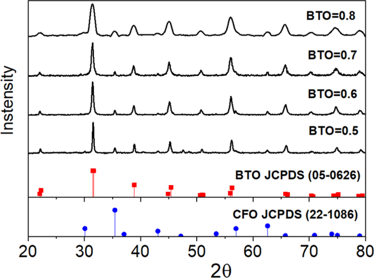
Room temperature x-ray diffraction patterns for different
samples of xBTO-(1-x)CFO (x = 0.5, 0.6, 0.7, 0.8) are shown in Fig.
2. The patterns confirmed the existence of both barium titanate and cobalt
ferrite phases. The peaks of the patterns coincide the peaks of both spinell cubic
structure of ferromagnetic cobalt iron oxide with card ID (JCPDS 22-1086), and
the tetragonal peroskite structure of ferroelectric barium titanate with card
ID (JCPDS-0626) without any other interference phases. This is an
indication of two distinct phases with no new other phases
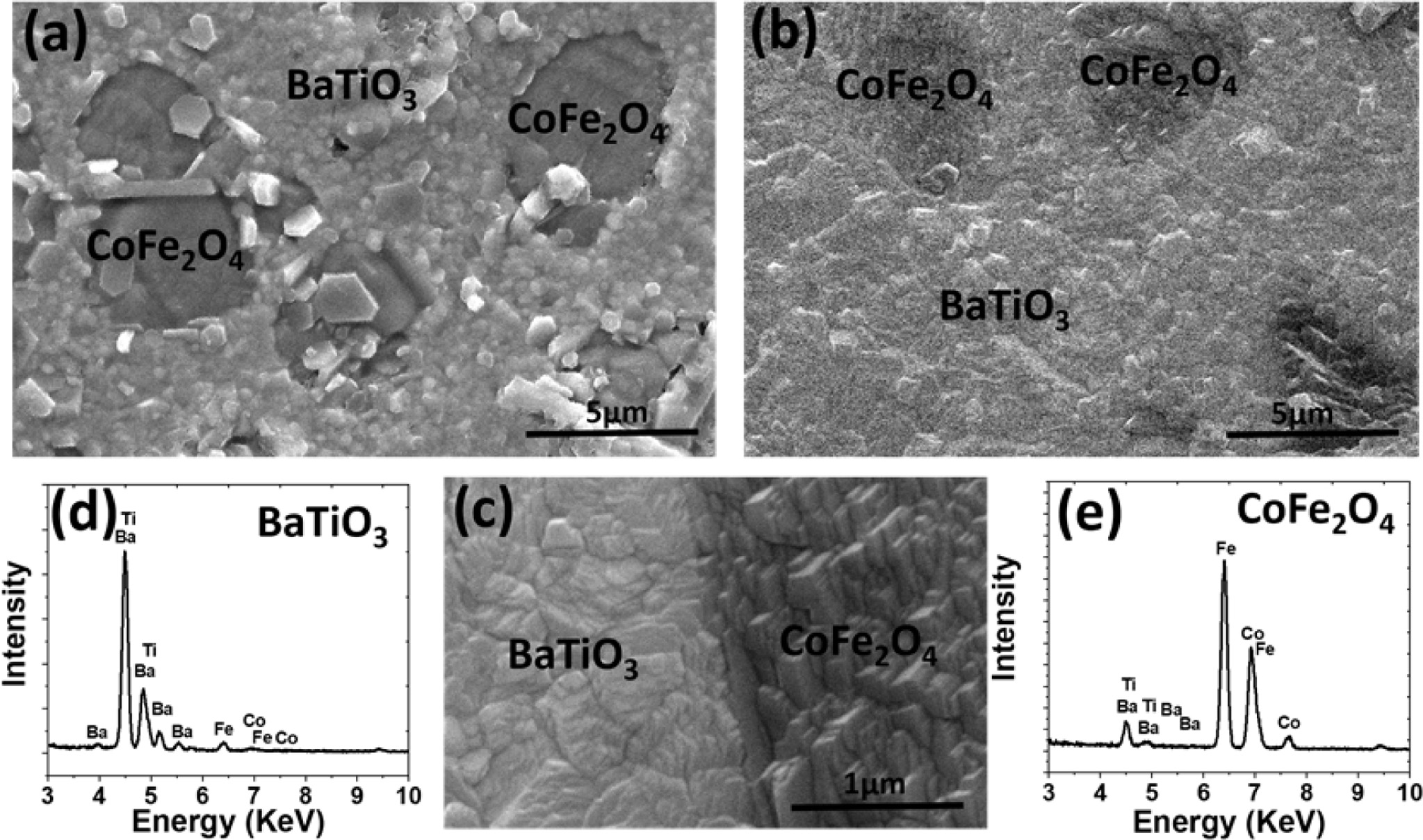
that may generate after high temperature sintering. Fig. 3 shows the surface
morphology for the synthesized samples using the scanning
electron microscopy. The separate distribution of the
magnetic phases of cobalt ferrite (black regions) in barium titantate matrix
(white regions) confirmed the (0-3) connectivity nature of the magnetoelectric
ceramic samples (see Figs. 3(a) and 3(b)). The well-defined and strong
interfaces between the constituents in composite magnetoelectric are prerequisites
in order to enhance the magntoelectric effect [22]. Fig. 3(c) shows a
magnification of the interface region between cobalt ferrite and barium
titante. The two regions are well-connected without any cracks or porous areas.
The elemental composition of the selected area was collected using energy
dispersive spectroscopy. Pure elements of Ba, Ti, Co, Fe are detected in the
regions (see Fig. 3(d) for barium titanate region and Fig. 3(e) for cobalt
ferrite region).
The concept of magnetoelectric effect ![]() is
based on the product properties obtained by a combination of two phases such as
magnetostrictive and piezoelectric phases as shown in the following equation:
is
based on the product properties obtained by a combination of two phases such as
magnetostrictive and piezoelectric phases as shown in the following equation:

where σmn and ![]() are
the stress and the strain tensors, respectively, djkl Cmnk and qim are
the piezoelectric coefficient, stiffness and piezomagnetic coefficient tensors,
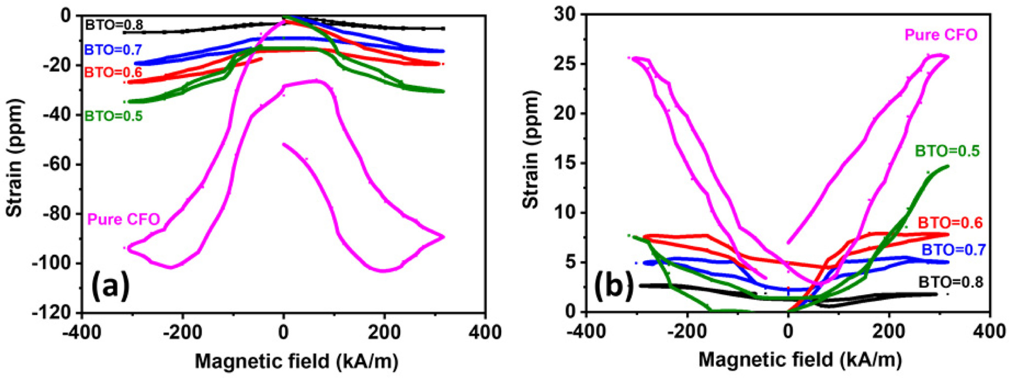
respectively. Fig. 4(a) shows the magnetostriction plots measured parallel to applied external magnetic field. It
is clear that the magnetostriction increased by increasing the content of the
magnetic phase in the samples. Maximum value of strain was recorded for the
sample of pure cobalt ferrite with values about -110 ppm. On
the other hand, the maximum value of magnetostriction of
composites was measured for the sample containing 50 percentage of barium
titatate with value about -40 ppm, these values are comparable with values
reported by Hrib et al. [23]. The low value of magnetostriction of
composite comparing to pure cobalt ferrite may be attributed to the
compression of barium titanate grains on the cobalt ferrite ones which may
reduce the overall magnetostriction.
Fig. 4(b) shows the magnetostriction of the samples measured perpendicular to
the external applied magnetic field. Lower values of magnetostriciton were
measured with maxiumum value for pure cobalt ferrite (≈25 ppm).
The lower values of magnetostriction obtained when the
magnetic field perpendicular to the applied magnetic field are attributed to
the magnetocrystalline anisotropy of cobalt ferrite [24].
are
the stress and the strain tensors, respectively, djkl Cmnk and qim are
the piezoelectric coefficient, stiffness and piezomagnetic coefficient tensors,
respectively. Fig. 4(a) shows the magnetostriction plots measured parallel to applied external magnetic field. It
is clear that the magnetostriction increased by increasing the content of the
magnetic phase in the samples. Maximum value of strain was recorded for the
sample of pure cobalt ferrite with values about -110 ppm. On
the other hand, the maximum value of magnetostriction of
composites was measured for the sample containing 50 percentage of barium
titatate with value about -40 ppm, these values are comparable with values
reported by Hrib et al. [23]. The low value of magnetostriction of
composite comparing to pure cobalt ferrite may be attributed to the
compression of barium titanate grains on the cobalt ferrite ones which may
reduce the overall magnetostriction.
Fig. 4(b) shows the magnetostriction of the samples measured perpendicular to
the external applied magnetic field. Lower values of magnetostriciton were
measured with maxiumum value for pure cobalt ferrite (≈25 ppm).
The lower values of magnetostriction obtained when the
magnetic field perpendicular to the applied magnetic field are attributed to
the magnetocrystalline anisotropy of cobalt ferrite [24].
Previously, the converse linear magnetoelctric effect αjji values
for different compositions were measured and reported
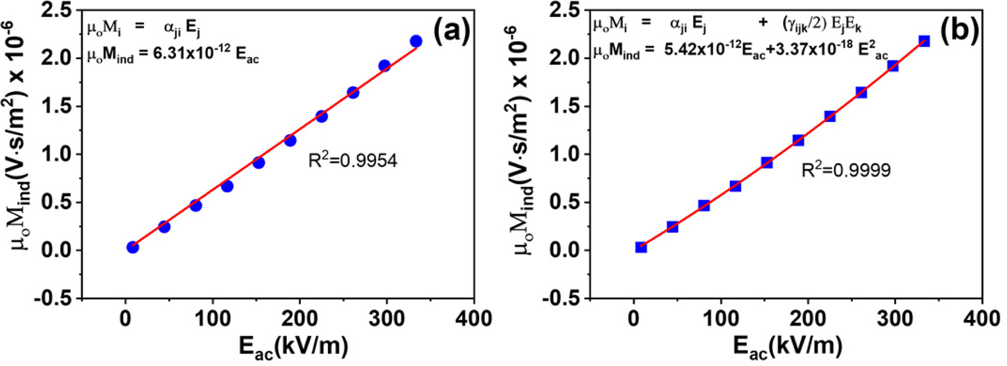
[25]. An example of the electrically induced
magnetization of the composite xBTO-(1-x)CFO when x = 0.7 in the
electric field range (0-350 kV/m) is shown in Fig. 5. The relation between
the induced magnetization and the electric field is linear where μoμi =αjiEj. The linearity of the magnetoelectric effect
was approved by different researchers and for different materials [26-28]. In
order to investigate the degree of linearity of the ME effect, the curve was
fitted using linear regression equation as shown in Fig. 5(a) and quadratic
equation (Fig. 5(b)). It was shown that the quadratic equation fitted the curve
perfectly with R-square value 0.9999 which is an indication of the appearance
of the second order ME effect (γijk). For the second order magnetoelectric
effect γijk, it is known that this effect depends mainly
on the square of the electric field as indicated in Eq. (2) (see Fig. 5(b)).
For more explanation, the electric field was applied to
the sample perpendicular to the sample surface so that the converse
magnetoelectric effect - as shown in equation number (2)- can be calculated
considering the applied electric field vector E3=(0,0,E3),
so:
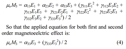
Then, the values of first order ME effect a33 can
be calculated by dividing the induced magnetization on the electric field and
the unit will in s/m, and the value of g333
can be calculated by dividing the induced magnetization by the square of
electric field, so that the unit of the second order magnetoelectric effect g will in s/V. To our knowledge,
this unit of quadratic magne- toelectric
effect has not been measured for any composite magnetoelectric material, while
it has rarely been reported but for single phase materials only. The sample
procedures for fitting curves were followed for the set of different
compositions of xBTO-(1-x)CFO where (x = 0.5, 0.6, 0.7 and 0.8).
Then, the quadratic magnetoelectric effect for different compositions was
extracted and shown in Fig. 6. The same as the first order magnetoelectric
effect, it is clear that the effect depends on the composition between the
ferroelectric and ferromagnetic phases, where the greatest value was recorded
for the composition when x = 0.5. This can be explained by larger
interfaces between the two phases can be obtained when the fifty percent of the
composite are ferromagnetics distributed in ferroelectric matrix, and hence,
more strain generated by electrostriction and transferred to piezomagnetic
phase [29]. The maximum room temperature value of the quadratic magnetoelectric
effect g at
x = 0.5 reached to about 20 × 10-18 s/V whereas
the value of 6.46 ps/MV was measured for Co4Nb2O9
single crystal and at 10K [30]. The quadratic magnetoelectric effect of the
barium titanate cobalt ferrite composite is three times larger than the single
phase values and even at room tem- perature. We believe that having (0-3)
composites, the interface between the two phases with 50% weight percent will
be higher and consequently give higher linear and quadratic ME effect as
indicated in Fig. 6. The results obtained from this paper may be utilized by
other researchers in order to measure linear and quadratic magnetoelectric
effect for other composites with other phase connectivity.
|
Fig. 2 X-ray diffraction patterns for different compositions of
ceramic samples of barium titanate and cobalt ferrite composites. |
|
Fig. 3 Scanning electron micrographs for samples (a) x = 0.5 (b) x = 0.8 and (c) the interface between ferromagnetic and ferroelectric phases
(d) energy dispersive spectroscopy for the barium titanate phase and (e) energy dispersive spectroscopy for cobalt ferrite phase. |
|
Fig. 4 Magnetostriction of barium titanate/cobalt ferrite composites (a) measured along the direction of the external applied magnetic field
(b) measured perpendicular to the external applied magnetic field. |
|
Fig. 5 Room temperature induced magnetic moments as a function of applied electric field, for composition x = 0.7 showing (a) linear
equation fit (b) quadratic equation fit (f = 3 Hz, Hdc = 1500 Oe). |

|
Fig. 6 Room temperature second order (γ) magnetoelectric effect
for different composition of xBTO-(1-x)CFO composites measured
at Hdc = 1500 Oe, f = 3 hz. |
In summary, the quadratic magnetoelectric effect for
different compositions of barium titante and cobalt ferrite
ceramic composites has been successfully extracted by the
employment of fitting quadratic equation of the first order one. The values of
the quadratic magne- toelectric
coupling coefficient (g)
in unit of S/V were reported for the first time for a composite material. The
maximum value of the quadratic magnetoelectric coupling coefficient for such
composite was recorded when the weight percentage of barium titanate is 50% of
the total composite weight with a value of γ333 = 20 × 10-18
s/V. The same as the first order magnetoelectric effect, it was also shown that
the quadratic magnetoelectric effect depends on the constituents amounts of the
ferroelectric/ferrimagnetic phases too. The existence of both the first and the
second order magnetoelectric effect is beneficial for future
applications such as the nonlinear magnetoelectric devices. This
study inspires other researchers to study the relationship
between the first and the second order ME effect in composites rather than
single phases magnetoelectrics.
- 1. Y.K. Fetisov, D.A. Burdin, D.V. Chashin, and N.A. Ekonomov, IEEE Sens. J. 14 (2014) 2252-2256.
-

- 2. M. Bibes and A. Barthelemy, Nat. Mater. 7 (2008) 425-426.
-

- 3. S. Dong, J.F. Li, and D. Viehland. Appl. Phys. Lett. 85 (2004) 3534.
- 4. T. Onuta, Y. Wang, C.J. Long, and I. Takeuchi, Appl. Phys. Lett. 99 (2011) 203506.
-

- 5. C. Pettiford, S. Dasgupta, J. Lou, S.D. Yoon, and N.X. Sun, IEEE T. Magn. 43 (2007) 3343-3345.
-

- 6. M. Fiebig, J. Phys. D: Appl. Phys. 38 (2005) R123.
-

- 7. L. Mitoseriu, J. Span. Cer. Glas. Soc. 44 (2005) 177-184.
-

- 8. M. Mercier, G. Velleaud, and J. Puvinel, Physica B+C. 86-88 (1977) 1089-1090.
-

- 9. J. Cardwell, Phys. Status Solidi B. 45 (1971) 597.
- 10. S. Takano, E. Kita, K. Siratori, K. Kohn, S. Kimura, and A. Tasaki, J. Phys. Soc. Jpn. 60 (1991) 288-293.
-

- 11. F.L. Zabotto, F.P. Milton, A.J. Gualdi, A.J.A. de Oliveira, J.A. Eiras, and D. Garcia, J. Alloy Compd. 829 (2020) 154517.
-

- 12. G. Jian, H. Shao, C. Yan, N. Zhao, B. Song, and C.P. Wong, J. Magn. Magn. Mater. 449 (2018) 263-270.
-

- 13. H. Song, M. Peddigari, A. Kumar, S. Lee, D. Kim, N. Park, J. Li, D. R. Patil, and J. Ryu, J. Alloy Compd. 834 (2020) 155124.
-

- 14. Z. Zheng, P. Zhou, Y. Liu, K. Liang, R.G. Tanguturi, H. Chen, G. Srinivasan, Y. Qi, and T. Zhang, J. Alloy Compd. 818 (2020) 152871.
-

- 15. P. Kaviraj, R. Pramanik, and A. Arockiarajan, J. Ceram. Int. 45 (2019) 12344-12352.
-

- 16. K.Y. Fang, L.H. Gong, W.Q. Jing, and F. Fang, Mater. Today Commun. 21 (2019) 100650.
-

- 17. L. Jian, A.S. Kumar, C.S. Chitra Lekha, S. Vivek, I. Salvado, A. L. Kholkin, and S.S. Nair, Nano Structures and Nano. Objects. 18 (2019) 100272.
-

- 18. D.A. Burdin, D.V. Chashin, N.A. Ekonomov, L.Y. Fetisov, Y.K. Fetisov, G. Sreenivasulu, and G. Srinivasan, J. Magn. and Magn. Mat. 358-359 (2014) 98-104.
-

- 19. J. Ma, Z. Li, Y. Lin, and C.W. Nan, Magn and Magn. Mater. 323 (2011) 101-103.
-

- 20. Y. Wang, Y. Shen, J. Gao, M. Li, J. Li, and D. Viehland, Appl. Phys. Lett. 102 (2013) 102905.
-

- 21. P. Borisov, A. Hochstrat, V.V. Shvartsman, and W. Kleeman, J. Rev. Sci. Instr. 78 (2007) 106105.
-

- 22. C.-W. Nan, M.I. Bichurin, S. Dong, D. Viehland, and G. Srinivasan, J. of appl. phys. 103 (2008) 031101.
-

- 23. L.M. Hrib and O.F. Caltun, J. Alloy. Compd. 509 (2011) 6644-6648.
-

- 24. R.M. Bozorth and J.G. Walker, Phys. Rev. 88 (1952) 1209.
-

- 25. M. Etier, V.V. Shvartsman, S. Salamon, Y. Gao, H. Wende, and D.C. Lupascu, J. Amer. Cer. Soc. 99 (2016) 1-9.
-

- 26. P. Yanda, N.V. Ter-Organessian, and A. Sundaresan, J. Phys. Rev. B. 100 (2019) 104417.
-

- 27. X. Shen, L. Zhou, Y. Chai, Y. Wu, Z. Liu, Y. Yin, H. Cao, C. Cruz, Y. Sun, C. Jin, A. Munoz, J. Alonso, and Y. Long, J. NPG Asia Mat. 11 (2019) 50.
-

- 28. D. Viehland, M. Wuttig, J. McCord, and E. Quandt, MRS Bull. 43 (2018) 834-840.
-

- 29. Y. Wang, J. Hu, Y. Lin, and C.-W. Nan, NPG Asia Mat. 2(2010) 61-68.
-

- 30. Y. Cao, G. Deng, P. Beran, V Feng, B. Kang, J. Zhang, N. Guiblin, B. Dkhil, W. Ren, and S. Cao, Sci. Rep. 7 (2017) 14079.
-

 This Article
-
2020; 21(5): 565-570
Published on Oct 31, 2020
- 10.36410/jcpr.2020.21.5.565
- Received on Apr 22, 2020
- Revised on Jun 5, 2020
- Accepted on Jun 10, 2020
 Services
Shared
 Correspondence to
- Morad Etier
-
Industrial Engineering Department, The Hashemite University, Zarqa 13133, Jordan
Tel : +962 (5) 3903333-5013
Fax: +962 (5) 3826613 - E-mail: morad.etier@hu.edu.jo


 Copyright 2019 International Orgranization for Ceramic Processing. All rights reserved.