- Effect of the conductive materials and press ratio of an anode electrode on the electrical properties in a lithium-ion battery using SiOx
Jong-Kyu Lee and Jung-Rag Yoon*
R&D Center, SAMWHA CAPACITOR, Yongin, South Korea
A Lithium-ion battery was
prepared by controlling the content of conductive materials and the press ratio
of the anode electrode to optimize cell properties. Increasing of the content
of conductive material, increased the capacity, and decreased the DC-ESR. The
discharge capacity retention as a function of current rates increased with an
increasing amount of conductive material. With an increasing press ratio, the
active material was evenly distributed on the Cu collector and a dense anode
was obtained. The capacity and DC-ESR decreased with an increasing press ratio.
The discharge capacity and DC-ESR retention as a function of current rates did
not change remarkably with an increasing press ratio. However, the adhesion
force between the Cu collector and active materials increased with an
increasing press ratio.
Keywords: Li-ion battery, SiOx, Conductive materials, Press ratio
Lithium-ion batteries (LIBs) have been established as one
of the most important energy storage technologies and are widely used in
importable electronics and electric vehicles (EVs) because of their high energy
and power densities as well as long lifespan [1-4]. However, the
increasing energy density and cost demands for general
public acceptance of EVs have begun to exceed the ultimate capability of
current commercial LIB technology [5-8].
Silicon monoxide (SiO) has recently aroused great interest
as one of the most promising alternative anode materials for
next-generation LIBs due to its appropriate working
potential (< 0.5 V vs. Li+/Li), high theoretical specific
capacity (-2,400 mAh g−1), and enhanced cycling
stability compared to Si [9-13]. Silicon monoxides (SiO or SiOx)
have also received some attention as another type of silicon-based anode
because of their based on its ability to offer high energy density while they
suffer from poor electronic conductivity [14].
A conductive additive as a necessary ingredient has been
widely used in the lithium ion battery system to enhance the
conductivity of electrodes [15-18], especially for the
Si-based anode [19, 20]. Conductive additive wrapping around the active
material grains has greatly reduced the contact resistance
between grains, decreased the inner resistance and improved the
rate capability [21]. At present, the commonly used conductive
additives in commercial lithium ion batteries are acetylene black,
Super-P, Ketjen Black, CNTs and vapor-grown carbonfibers (VGCFs).
In this paper, Super-P was chosen as a conductive material
for a SiOx/graphite composite anode. We investigated the
effect of the amount of conductive material and the mechanical press ratio of
the anode electrode on the electrical properties for lithium ion batteries
using a SiOx
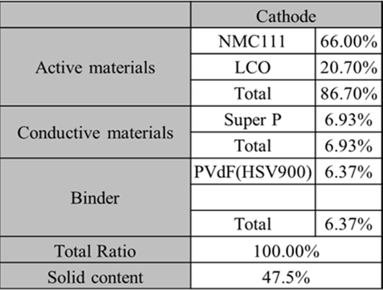
To prepare a cathode electrode, as shown in Table 1(a)
below, NMC111 (LiNiMnCoO2) and LCO (LiCoO2)
as an active material, Super-P (Timcal) as a conductive material,
and PVdF (HSV900) as a binder were slurried at a ratio
of 86.7:6.93:6.37 (vol%) in an NMP (n-methyl-2-pyrrolidone) solvent; the slurry
was coated on an etched Al foil, and then pressed. The thickness of the coated
cathode electrode was adjusted to 130 μm after it was pressed, and the
electrode density was 29 mg/cm2. To prepare an anode electrode, as
shown in Table 1(b), artificial graphite (Sigma Aldrich, 10 μm) and SiOx
were used as anode active materials, Super-P was used as a
conductive material, and a mixed aqueous binder of
CMC (carboxylmethyl cellulose) and PAA (polyacrylic acid) was used as a binder.
Artificial graphite and SiOx (x=1; a product manufactured by
OTC company; average particle diameter: 5 μm) were set at 9:1, and slurries
were prepared in a DI water solvent while the content of the conductive material
super-p was changed to 2%, 6% and 10%, and then it was coated on Cu foils and
pressed, thereby preparing anode electrodes. The thickness of the coated anode
electrode according to the content of the conductive material was set at 100 μm
after pressing, and then the electrode density was adjusted to 9.8 to 11.0
mg/cm2 depending on the press ratio. To fabricate a lithium
secondary battery unit cell, we used the same cathode as described
above, and prepared a jelly-roll by winding using a cellulose-based
separator, and finally we immersed it in a
1.5 M LiPF4/acetonitrile electrolyte for 24 hours, and then sealed
using a curing method in a
cylindrical can with a 2245 size. The fabricated lithium secondary battery unit cell was measured for its
charge/discharge and rate characteristics (C-rate) using an Arbin cycler. To
confirm the crystallinity of powdery SiOx samples, X-ray
diffraction analysis (XRD, D/MAX 2000 by Rigaku Corp.) was performed using Cu Kα1
rays (1.5406 Å). Each sample was measured at 20o to 80o with a scan speed of 5o min-1
(40 kV, 100 mA). Table 2
|
Table 2 Composition of the anode as a function of the amount of conductive material. |
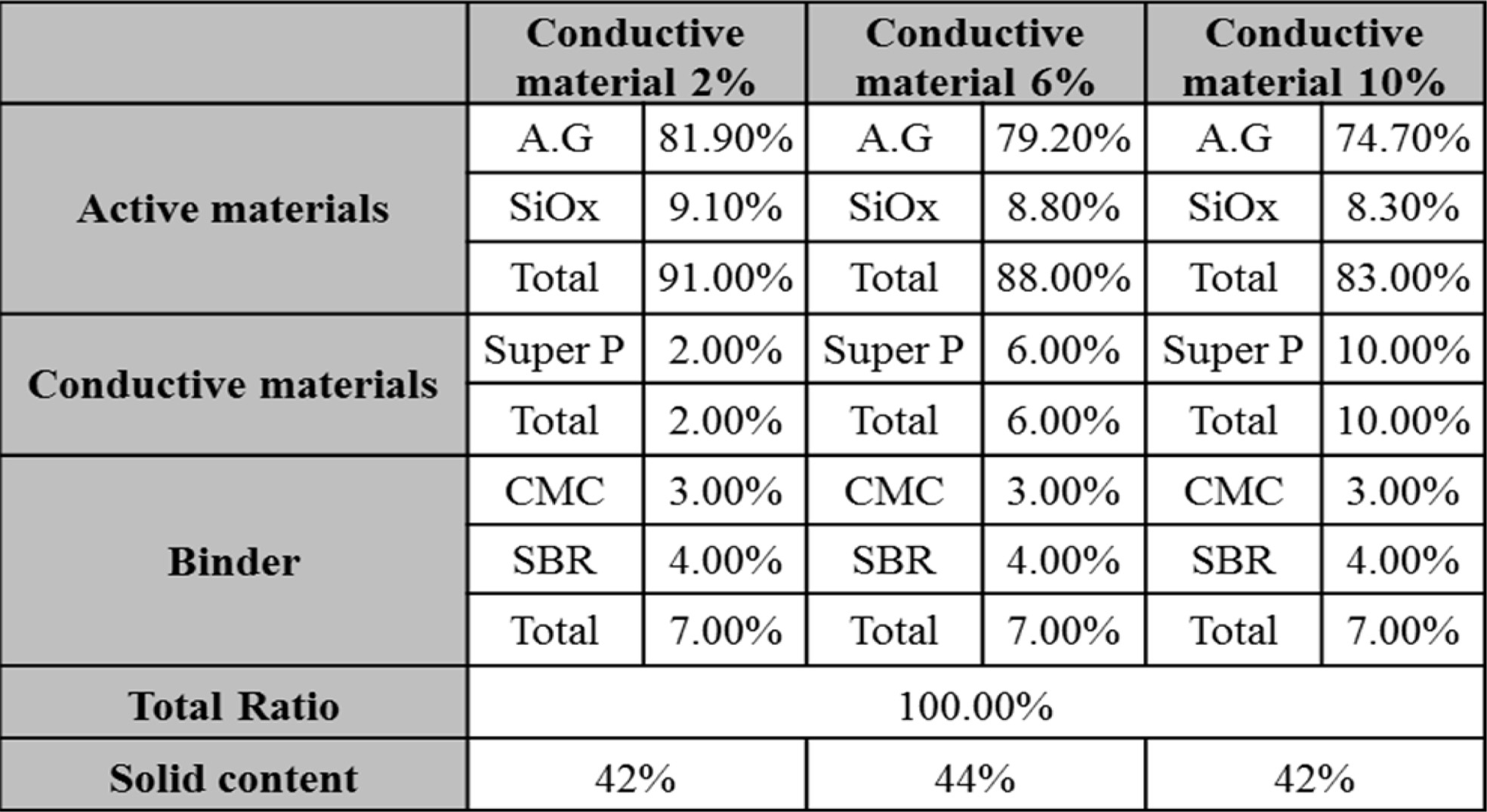
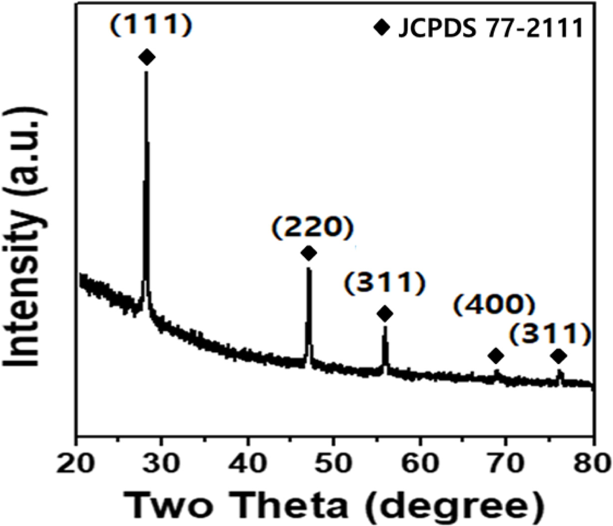
Fig. 1 shows the results of the XRD analysis of the SiOx
used in this experiment. The diffraction of the (111), (220), (311), (400) and
(331) planes appeared at 28.4o, 47.3o, 56.1o, 69.1o
and 76.3o, and these results are identical to those of JDPDS Card
JCPDS No. 77-2111.
Characteristics
as a function of the amount of conductive material of in the anode electrode
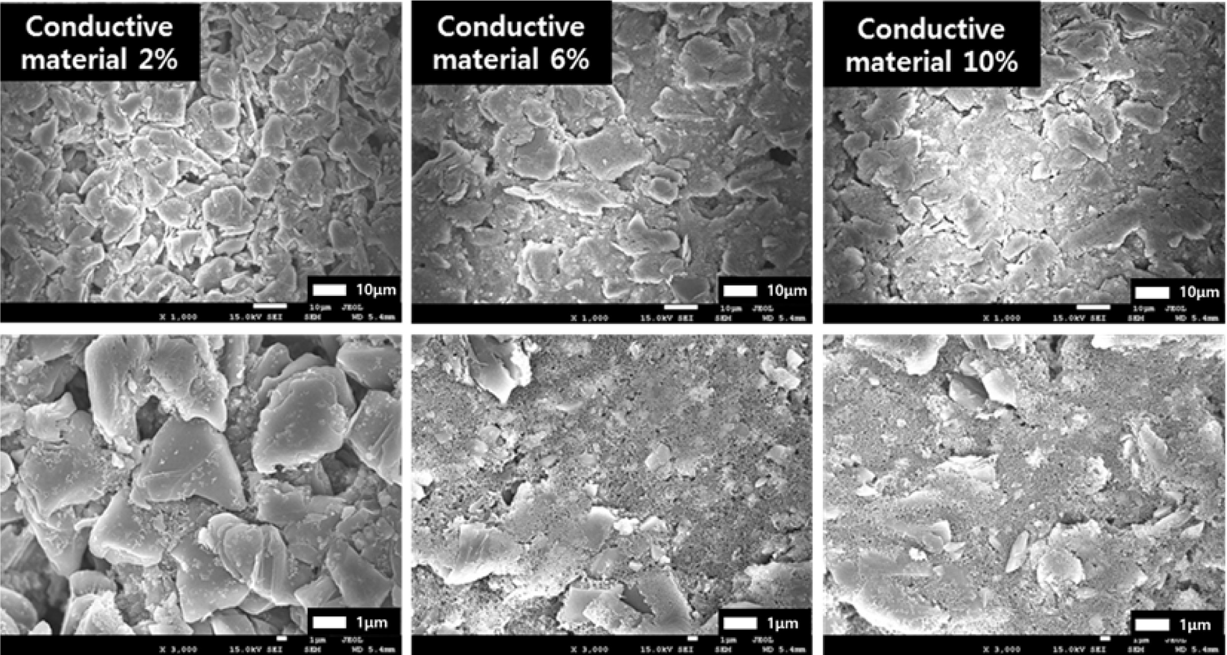
Fig. 2 depicts FE-SEM images of the anode electrodes
as a function of the amount of conductive material, The conductive material is
uniformly distributed in the space between the artificial graphite and the SiOx
particles and around the particles as the content of the conductive material
which has a structure in which 20 to 30 nm particles are connected to one
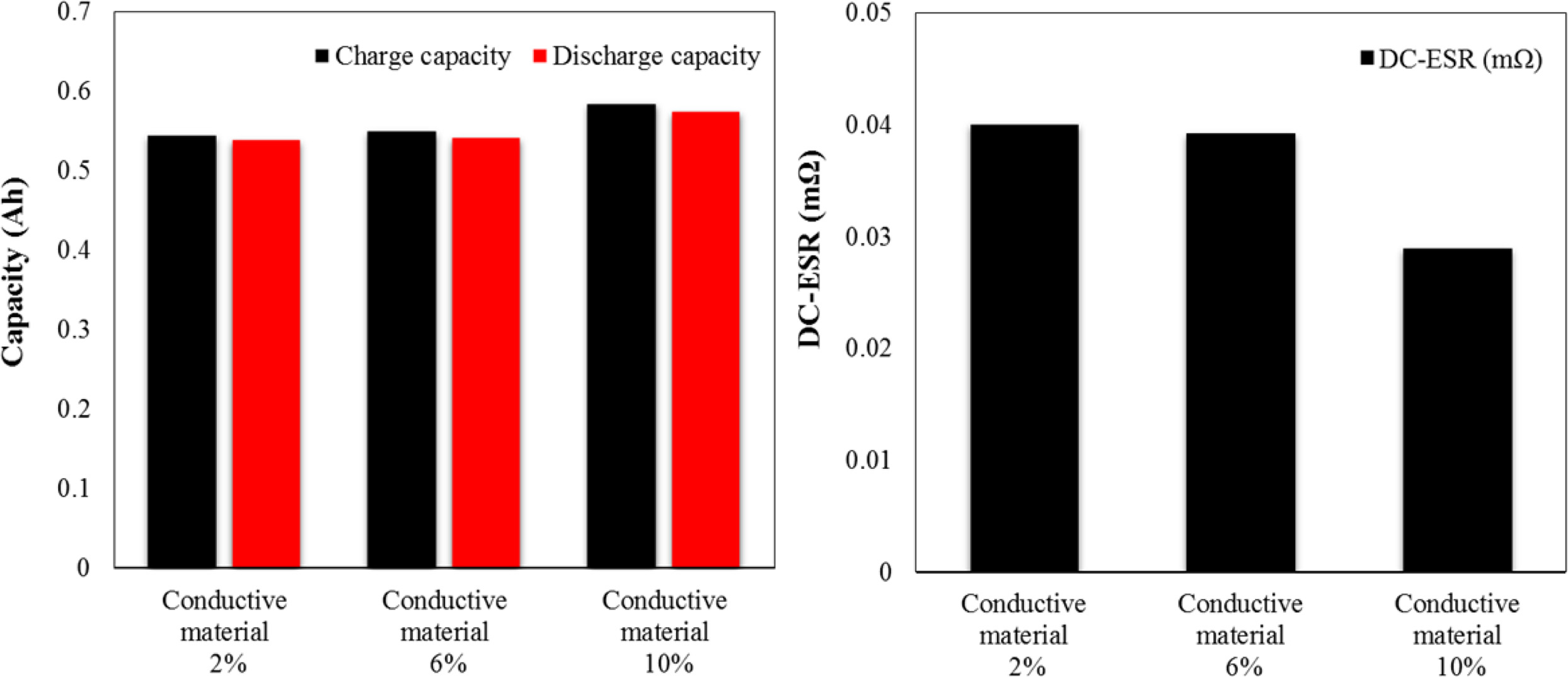
another like chains is increased. Fig. 3 shows the results of
measuring electrical characteristics as a function of the
conductive material content by performing charge/discharge at 1C. The charge
capacity and the discharge capacity show a tendency to increase as the amount
of conductive material increases. The DC-equivalent series resistance is
as low as 0.028 Ω when the content of the conductive
material is 10%. We obtained the result for the charge/discharge capacity and
DC-equivalent series resistance characteristics because the conductive
material, Which had high conductivity was uniformly distributed in the space
between the active materials as confirmed by the FE-SEM image of the anode
electrode in Fig. 2, thereby facilitating the migration of lithium ions to the
artificial graphite and the SiOx active material.
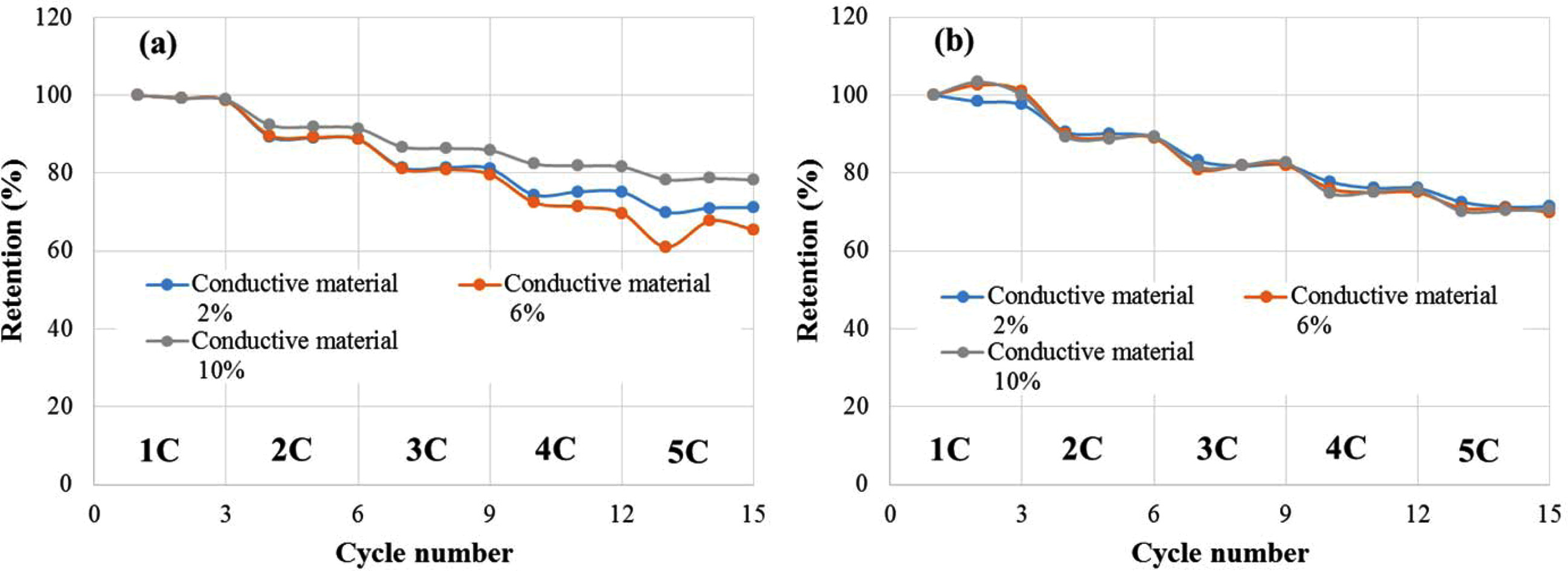
Fig. 4 shows the results obtained by charging the cell at
1C to 5C-rate, and then maintaining for 10 seconds in the CV region, and then
discharging at the same current as the charge current and measuring the C-rate
for each three cycles. The results of the C-rate mea- surement indicated that the capacity
retention increased as the content of the conductive material content
increased and that the lithium ion battery fabricated using the
electrode with a conductive material of 10% had a discharge capacity retention
of 78% at 5C compared to 100% at 1C. The DC-equivalent series resistance did
not significantly change according to the change in the conductive
material content, while the discharge capacity did.
Characteristics
as a function of the anode electrode
The delamination between the Cu foil (current collector)
and the coating layer when a cell is fabricated using
lithium secondary battery electrodes influences the fabrication process and
reliability characteristics. In the anode electrode experiment we performed as
a function of the conductive material content, the press ratio was set at 10%
and the delamination between the Cu foil (current collector) and the coating
layer was measured
as a function of the conductive material content.
In the result, average adhesion forces of 0.0627, 0.0128 and 0.01 kgf appeared at conductive material contents of 2, 6
and 10%. The results of the experiment performed as a function of the
conductive material content indicated that with an electrode with a
conductive material content of 10%, which showed the best charge/discharge
characteristics and C-rate characteristics,
a problem arose: The adhesion force between the current collector and the
coating layer decreased.
This was because the amount of the conductive material
with a nano-scale size and a large specific surface area increased, and thus
the area caught by the binder increased. In order to increase the adhesion
force between the current collector and the coating layer, we set the
composition as shown in Table 1 and performed pressing using a press at press
ratios of 10, 20 and 30%, and then we examined the adhesion force and
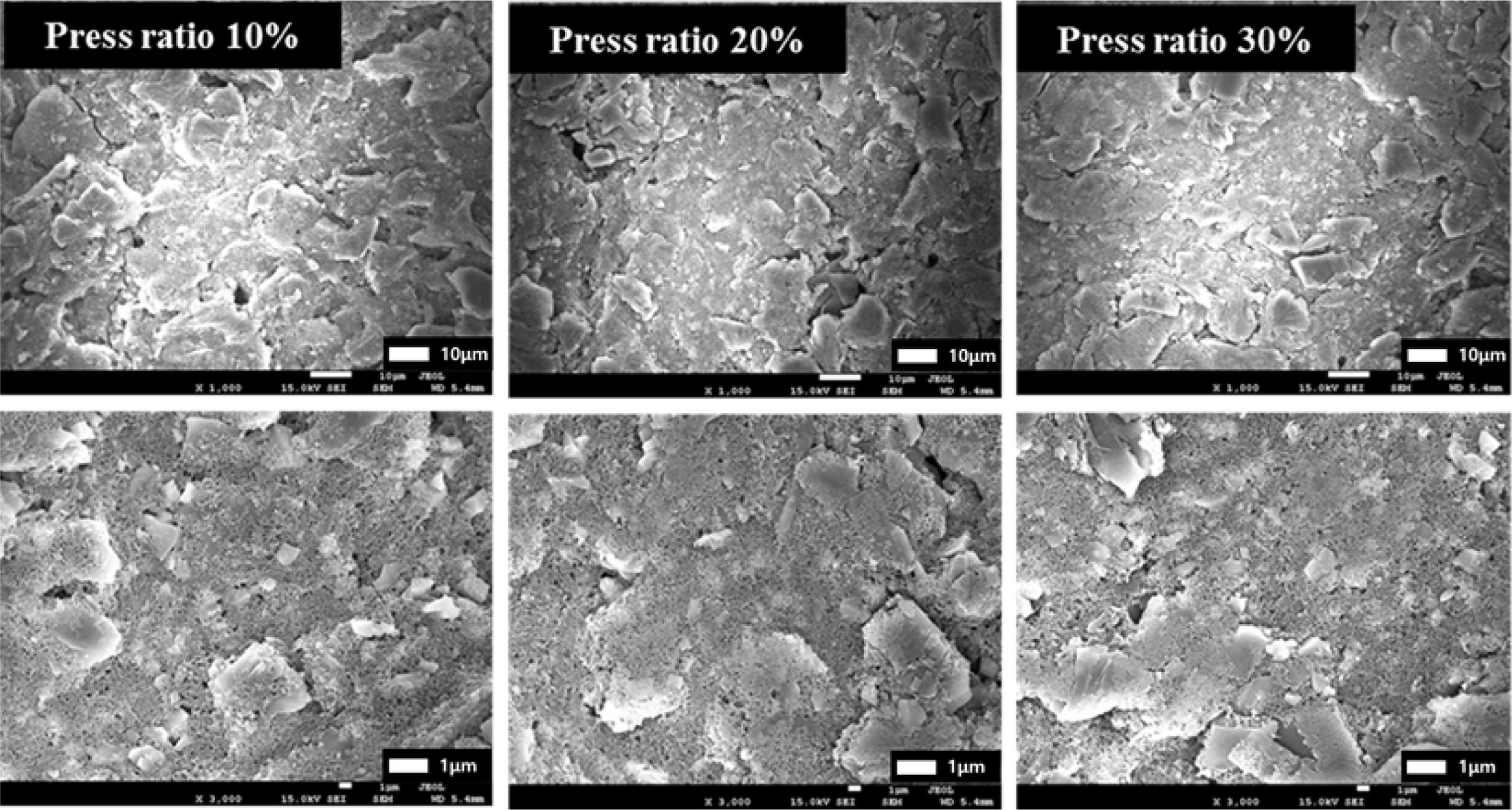
electrical characteristics. Fig. 5 depicts FE-SEM images as a function of the
pressure ratio: As the press ratio increases, particles are pushed and pores
decrease. We thought that the distance between the current collector and the
coating layer decreased because of the increase in the press rate, and the
active material and the conductive material were closely connected to each
other.
We fabricated lithium ion battery unit cells and compared
the amount of impregnated electrolyte with press ratios. The amount of
impregnated electrolyte decreased to 6.63, 6.23 and 5.77 g at press ratios of
10, 20 and 30%, respectively. From the FE-SEM images and the experiment on the
amount of impregnated electrolyte, we confirmed that the
pores in the electrolyte decreases as the press ratio
increased.
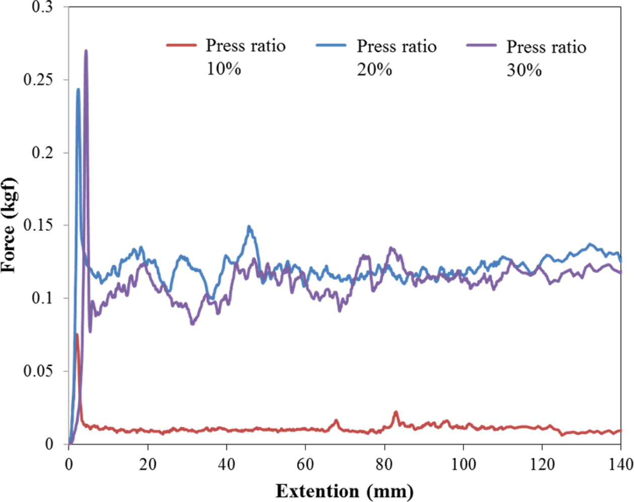
Fig. 6 shows the results for the measurement of the
adhesion force between the Cu current collector and the coating layer as a
function of the press ratio. The average adhesion forces are 0.01, 0.117 and
0.095 kgf at press ratios of 10, 20 and 30%, indicating that the highest occurs
at a press ratio of 20%.
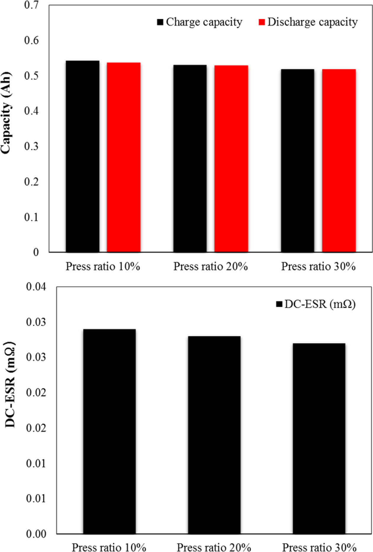
Fig. 7 shows the measurement results for the electrical
characteristics as a function of the press ratio with the performance of
charge/discharge at 1C. The charge/discharge capacities and the DC-equivalent
series resistance show a tendency to decrease. We believe considered that the
decrease in the charge/discharge capacities was due to the decrease in the amount
of impregnated electrolyte and that the decrease in the DC-equivalent series
resistance was because of the decrease in the distance between the current
collector and the coating layer due to the increase in the press ratio rather
than the influence of the amount of impregnated electrolyte and because of the
compact connection between the active material and the conductive material.
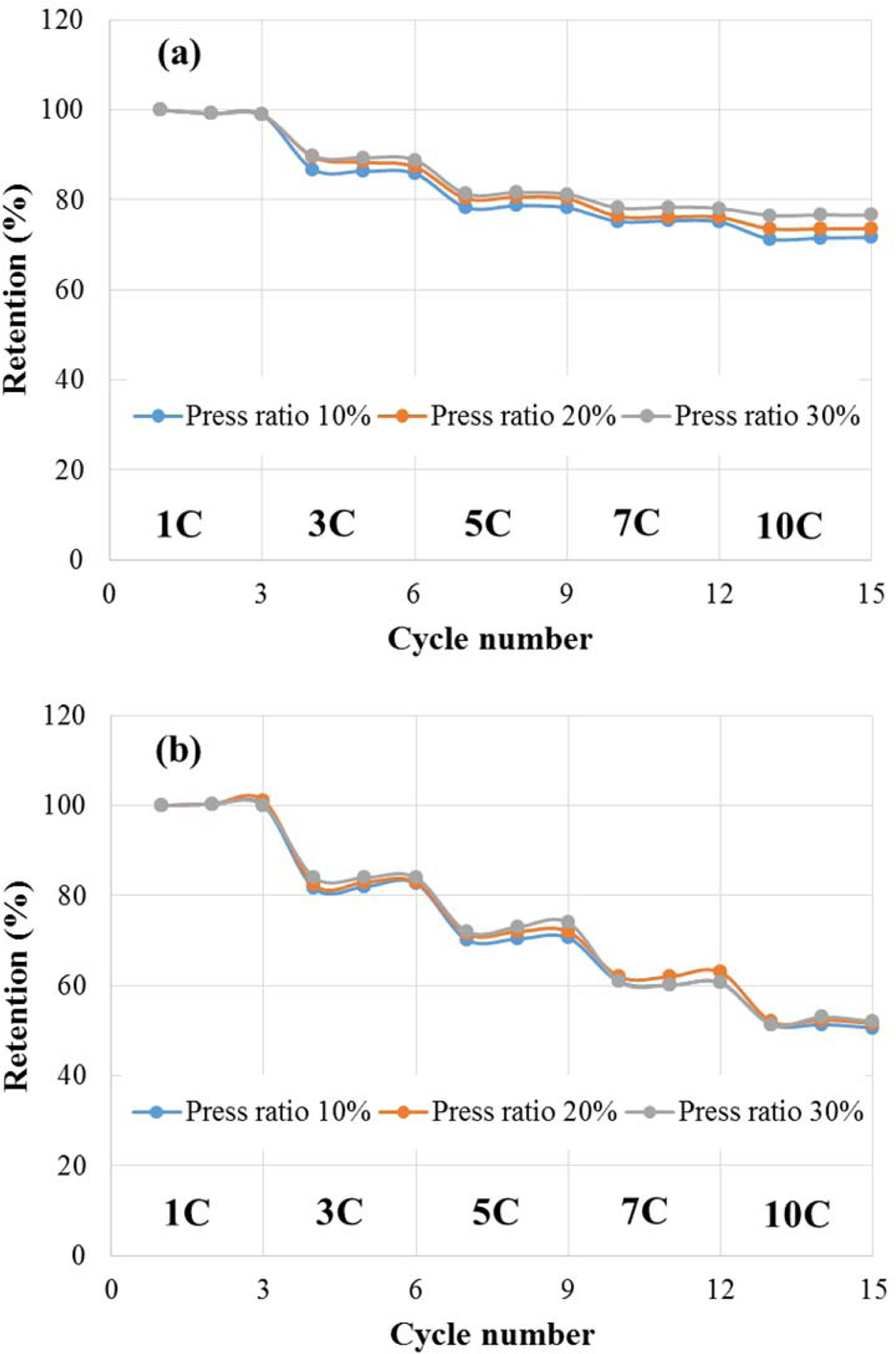
Fig. 8 shows the results obtained for charging the cell at
1C to 10C-rate, and then maintaining it for 10 seconds in the CV region, and
then discharging it at the same current as the charge current and measuring the
C-rate for each three cycles. The results of the C-rate measurement indicated
that the discharge capacity retention at a press ratio of 30% was 76.6% at 10C compared
to 100% at 1C. Unlike the discharge capacity, the
DC-equivalent series resistance did not significantly change
according to the change in the amount of conductive material.
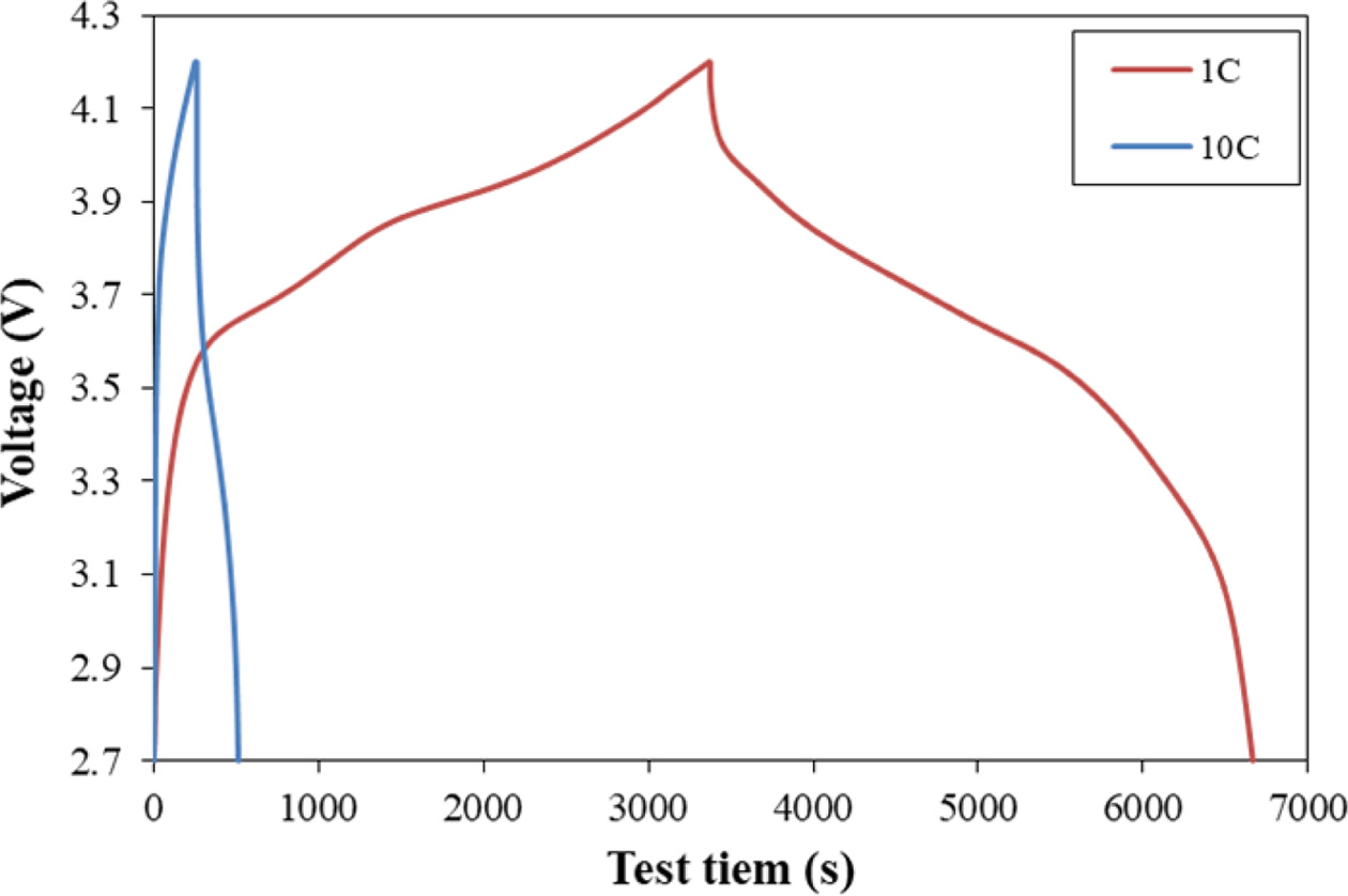
The charge/discharge curve of the cell at a press ratio of
30% as a function of current rate is shown Fig. 9. The charging and discharging
time at 1C was 6664 seconds, and the charging and discharging time at 10C was
513 seconds. The discharge capacity at 10C was 76.6% while it was 100% at 1C.
|
Fig. 1 Results of the XRD measurement of SiOx |
|
Fig. 2 FE-SEM images of anode electrodes as a function of the amount of conductive material. |
|
Fig. 3 Capacity and DC-ESR as a function of the amount of conductive material. |
|
Fig. 4 C-rate as a function of the amount of conductive material: (a) capacity retention. (b) DC-ESR retention. |
|
Fig. 5 FE-SEM images of anode electrodes as a function of the pressure ratio. |
|
Fig. 6 Adhesion force of anode electrodes as a function of the
press ratio. |
|
Fig. 7 Capacities and DC-ESR as a function of the press ratio of
the anode electrode. |
|
Fig. 8 C-rate as a function of press ratio: (a) capacity retention, (b)
DC-ESR retention. |
|
Fig. 9 The charge/discharge curve of cell with press ratio 30% as
a function of current rate. |
In this study, in order to develop a lithium secondary
battery, that is capable of charging/discharging even at high current rates,
using SiOx as an anode active material, we evaluated the
electrical characteristics as a function of the amount of conductive material
and the press ratio. We adjusted the content of the conductive material to 2, 6
and 10 wt% and evaluated the electrical characteristics were evaluated. We
found that as the content of the conductive material increased, the capacity
increased and the resistance decreased. The c-rate was measured at 1 to 5C, and
the cell with a conductive material content of 10 wt% showed the best capacity
retention according to the change in charge current.
We performed the evaluation while changing the press ratio
of the electrode with a conductive material content of 10 wt%, and as a result,
the capacity and resistance decreased as the press ratio increased. The C-rate
was measured at 1 to 10C, and the cell with the highest press ratio (30%)
showed the best capacity retention (76.6%) at 10C compared to that of 1C, and
the adhesion force of the anode electrode was also excellent.
Our study confirmed that the lithium secondary battery
fabricated using SiOx achieved a capacity retention of 70% or
higher in rapid charge/discharge at 10C and had the potential as a lithium
secondary battery that is capable of rapid charging/discharging.
This work was supported by the Technology Innovation
Program (10080656, Development of ceramic/carbon convergence and integration
anode material for 10C fast charging Lithium ion battery) funded By the Ministry
of Trade, Industry & Energy (MOTIE, Korea).
- 1. C.P. Grey and J.M. Tarascon, Nat. Mater. 16 (2017) 45-56.
-

- 2. D. Larcher and J.M. Tarascon, Nat. Chem. 7 (2015) 19-29.
-

- 3. M. Armand and J.M. Tarascon, Nature. 451 (2008) 652-657.
-

- 4. X. Dong, Z. Guo, Z. Guo, Y. Wang, and Y. Xia, Joule 2 (2018) 902-913.
-

- 5. Y. Li, Y. Li, A. Pei, K. Yan, Y. Sun, C. Wu, L. Joubert, R. Chin, A.L. Koh, Y. Yu, J. Perrino, B. Butz, S. Chua, and Y. Cui, Science 358 (2017) 506-510.
-

- 6. P.G. Bruce, B. Scrosati, and J.M. Tarascon, Angew. Chem. Int. Ed. 47 (2008) 2930-2946.
-

- 7. N.-S. Choi, Z. Chen, S.A. Freunberger, X. Ji, Y.-K. Sun, K. Amine, G. Yushin, L.F. Nazar, J. Cho, P.G. Brucea, and Angew. Chem. Int. Ed. 51 (2012) 9994-10024.
-

- 8. J. Lee, D.A. Kitchaev, D.-H. Kwon, C.-W. Lee, J.K. Papp, Y.-S. Liu, Z. Lun, R.J. Clément, T. Shi, B.D. McCloskey, J. Guo, M. Balasubramanian, and G. Ceder, Nature 556 (2018) 185-190.
-

- 9. T. Chen, J. Wu, Q. Zhang, and X. Su, J. Power Sources 363 (2017) 126-144.
-

- 10. M. Ko, S. Chae, J. Ma, N. Kim, H.-W. Lee, Y. Cui, and J. Cho, Nat. Energy 1 (2016) 16113-16120.
-

- 11. D. Liu, Z. Liu, X. Li, W. Xie, Q. Wang, Q. Liu, Y. Fu, and D. He, Small 13 (2017) 1702000.
-

- 12. S. Chae, M. Ko, S. Park, N. Kim, J. Ma, and J. Cho, Energy Environ. Sci. 9 (2016) 1251-1257.
-

- 13. I.H. Son, J.H. Park, S. Kwon, J.W. Choi, and M.H. Rümmeli, Small 12 (2016) 658-667.
-

- 14. M.N. Obrovac and V.L. Chevrier, Chem. Rev. 114 (2014) 11444-11502.
-

- 15. K.L. Huang, Z.X. Wang, and S.Q. Liu, in “The Principle and Key Technology of Lithium Ion Battery”, (Beijing: Chemical Industry Press, 2008) p.38.
-

- 16. Y.P. Wu, J.Q. Ma, and X.B. Dai, in “Lithium Ion Battery: Application and Practice”, (Beijing: Chemical Industry Press, 2004) p.21.
-

- 17. X. Su, Q. Wu, J. Li, X. Xiao, A. Lott, W. Lu, B.W. Sheldon, and J. Wu, Adv. Energy Mat. 4 (2014) 1300882.
-

- 18. Z. Huang, K.D. Harris, and M.J. Brett, Adv. Mater. 21 (2009) 2983-2987.
-

- 19. H.H. Li, X.L. Wu, H.Z. Sun, K. Wang, C.Y. Fan, L.L. Zhang, F.M. Yang, and J.P. Zhang, J. Phys. Chem. C 119 (2015) 3495-3501.
-

- 20. B. Guo, J. Shu, Z. Wang, H. Yang, L.H. Shi, Y. Liu, and L. Chen, Electrochem. Commun. 10 (2008) 1876-1878.
-

- 21. Y. Ren, J. Ding, N. Yuan, and S. Jia, J. Solid State Electrochem. 16 (2012) 1453-1460.
-

 This Article
-
2020; 21(5): 533-538
Published on Oct 31, 2020
- 10.36410/jcpr.2020.21.5.533
- Received on Mar 4, 2020
- Revised on Apr 16, 2020
- Accepted on May 4, 2020
 Services
- Abstract
introduction
experimental
results and discussion
conclusions
- Acknowledgements
- References
- Full Text PDF
Shared
 Correspondence to
- Jung-Rag Yoon
-
R&D Center, SAMWHA CAPACITOR, Yongin, South Korea
Tel : +82-31-330-5765
Fax: +82-31-332-7661 - E-mail: yoonjungrag@samwha.com


 Copyright 2019 International Orgranization for Ceramic Processing. All rights reserved.