- Properties of ceramic fabricated of synthetic carbon and organoclay based on carbon particle size
Agus Edy Pramonoa,*, R. Sugeng Mulyonoa, R. Grenny Sudarmawana, Muhammad Zaki Nuraa, Haolia Rahmana and Nanik Indayaningsihb
aDepartment of Mechanical Engineering, Politeknik Negeri Jakarta, Jln. Prof. Dr. G.A. Siwabessy, Kampus UI. Depok 16425, Jawa-Barat, Indonesia
bResearch Centre for Physics, Indonesian Institute of Sciences, Kawasan Puspiptek, Gd. 440-442, Tangerang Selatan, Banten 15310, Indonesia
The electrical and thermal
conductivity properties of ceramics fabricated from carbon powder and clay have
been studied. This study was designed by varying the particle size of carbon
powders of mesh 150; 200; 250; 300; 350, with a carbon-organoclay ratio of 30:
70% by weight, 200 bar compacting, and sintering of 950; 1000; 1050 °C.
Electrical conductivity, thermal conductivity, specific wear rate,
density/porosity, and ceramic morphology have been studied. The thermal
conductivity follows the tendency of electrical conductivity, because of the
effect of carbon particle size. Increased sintering temperatures tend to
decrease wear resistance. The smaller the particle size of carbon powder, it
tends to increase the wear rate and the density of carbon-ceramic experiences
relatively small changes. Porosity tends to follow density, even though the
size of carbon particles gets smaller. The occurrence of porous and cracking is
more due to the irregular shape of carbon and matrix particles.
Keywords: electrical conductivity, thermal conductivity, carbon-ceramic, carbon particle size, organoclay
This study has succeeded in fabricating carbon-ceramic
from coconut coir organic waste materials as electrically conductive carbon
synthetic which is distributed in the organoclay as a ceramic matrix.
Organoclay is a ceramic matrix that is a local material from
Plered, Purwakarta, West Java, Indonesia. Synthetic carbon is
produced from organic coir coconut waste carbonized at
high temperatures (900 oC), producing the carbon
which is electrically conductive. The electrical conductivity properties,
mechanical properties of wear rate, physical properties of density
and porosity, thermal conductivity properties, and morphology of carbon-ceramic
composites have been studied. The relationship between
these properties has been analyzed and studied. The need
for friction mechanical parts that are resistant to wear and are electrically
conductive is the solution that will be offered from the results of the study.
The objectives of the research are development of alternative
types of electrically conductive of carbon-ceramic, developing geometric
alternatives and dimensions of conductor carbon particles for electrically
conductive ceramics, developing techniques and engineering pro- cesses for carbon-ceramic materials based on
coconut coir waste and clay, increasing the technological value of organic
waste coconut fiber, and clay, which are local ingredients. For decades, other
researchers have carried out research on ceramic that is electrically
conductive. Clay is an important component in making ceramic mixtures, because
of its plasticity, ease of use, strength and final properties obtained by heat
treatment [1, 2]. As a study conducted in 2015, developing carbon
black material from agricultural waste using the pyrolysis method at varied
carbonization temperatures and used as an amplifier in polymer composites [3].
The design of activated carbon-clay composites for waste decontamination made
from clay and carbon has been carried out. Fluesorb B was chosen as activated
carbon while a-sepiolite is a magnesium silicate clay used as an agglomerator
to achieve rheological charac-
teristics when mixed with activated carbon and water to confirm
ingredients in a monolithic, solid or tubular form [4]. Research on the
engineering of the use of coconut fiber into carbon-ceramic composites with
electrically conductive properties has been carried out. This research was
carried out experimentally based on coconut fiber with an
organoclay matrix. The properties of electrical conductivity, thermal
conductivity, and physical properties have been studied. This study
focuses on engineering carbon-ceramic composites with a clay matrix
[5]. New engineering, biochar with clay particles implanted
on the surface of carbon in the biochar pore has been successfully developed
[6]. The conductive aggregate type is prepared by calcining a ceramic matrix
and dispersed graphite powder. The conductive aggregate prepared was used in a
mortar containing carbon fiber, and the electrical resistivity and
piezoresis- tivity of the
specimen were studied [7]. Poly nano- composites
(ε-caprolactone) (PCL) with carbon nanotube particles
supported by clay loam (Clay-CNT) in concentration by weight were made by
mixing melt. The mechanical, structural and thermal properties of
nanocomposites are studied [8]. The 2015 study was to compare the fatigue
behavior and oxidation resistance of CC composites (carbon) derived from metals
with CC/ceramic composites (carbon/ceramics) obtained by impregnation of CC
composites with polysiloxane-based preceramic and subsequent heat treatment
[9]. This paper evaluates the effect of carbon nanotubes on the mechanical
properties and flame resistance of Homra / OPC blends; Homra is a solid waste
produced from the clay brick industry in Egypt [10]. Semi-finished
ceramic composites are consolidated with various starches and sintered at
different temperatures in the argon atmosphere. Electrical measurements, carbon
content and Raman analysis of carbon structures determine
the optimal sintering temperature of 1700 oC, which causes the
formation of a uniform conductive graphite network.
This carbon network produces porous composites that have high
electrical conductivity, which depends on the type of starch and porous
properties [11]. The composition of the ceramic material is prepared by
inserting up to 20 wt % of waste into two types of clay. The raw materials
used in this work are (a) one type of steel-making electric furnace waste to be
combined, and (b) two types of clay that significantly differs as a matrix.
The raw material is characterized by mineralogical
composition, chemical composition, and particle size distribution [12]. Carbon
fiber with hydrophilic surface modification is added to the mortar cement
through ultrasonic treatment. The mechanical and electrical properties of
carbon fiber cement mortar cement were tested to test the carbon fiber
strengthening effect [13]. A new ceramic of structured hybrids of nanocarbon
formed from organoclays during pyrolysis has been fabricated. It functions as a
reinforcement filler and binder for carbon/carbon (C/C) composites. The heat pressing
on the organoclay itself forms black monolithic sheets with
high thermal stability [14]. The nature of wear resistance and electrical
conductivity fabricated from the dispersion of coconut coir waste powder in the
organoclay matrix have been investigated [15], the study does not consider
carbon particle size as an electrically conductive filler. The
study is oriented mainly to the electrically conductive
properties, the composite wear resistance properties, the physical properties
of density and porosity, and composite elements. Carbon powder from coconut fibers
mixed with organoclay clay, with variations in composition 10:90, 20:80, and
30: 70% by weight. Composite molds are carried out by hydraulic machines in
tablet form [16]. Research on the use of sludge wastewater from industrial
uniform laundry as raw material combined with kaolin clay for the production of
white ceramics and the development of composites and
laboratory-level sustainable technology to produce white ceramics
has been carried out [17]. Based on studies of research on carbon-ceramic
composites that have been carried out by many other researchers, there has been
no research on carbon-ceramic composites with measurable powders, from
electrical conductivity carbon of coconut coir waste, and
organoclay as a matrix for ceramics with electrically conductive
and wear-resistant properties. State of the art of the research are:
Utilization of coconut fiber waste fiber as synthetic carbon material; The use
of organoclay clay as a matrix material of carbon-ceramic;
Engineering of ceramic based on waste materials and local
materials for wear-resistant and electrically conduc- tive materials; The repyrolysis
sintering process is a high-temperature combustion process to obtain two
ceramic characters, simultaneously in one process, electrically conductive and
wear-resistant. The process of sintering to form organoclay into ceramics,
while the repyrolysis process to form carbon becomes electrically conductive.
The pyrolysis is a repyrolysis process, because the filler is already in the
form of synthetic carbon from organic waste; The repyrolysis sintering process
is carried out in a tightly closed reactor tube, without inert gas (nitrogen or
argon). The two-process experiments also contributed to the technology of
carbon-ceramic fabrication processes.
Material
preparation
Organoclay
is a local material as a ceramic matrix. Synthetic carbon powder is carbonized
at 900 oC from organic coir coconut waste. Organoclay elements
were examined by an X-ray Fluorescence
Analyzer TORONTECH TT - EDXPRT, the main element of the organoclay was silica
(51.4%), the same thing was done by other researchers with silica element (an
average of 50.5%) [18], 61.1% SiO2 element [19]. The results of testing the
organoclay elements are shown in Table 1.
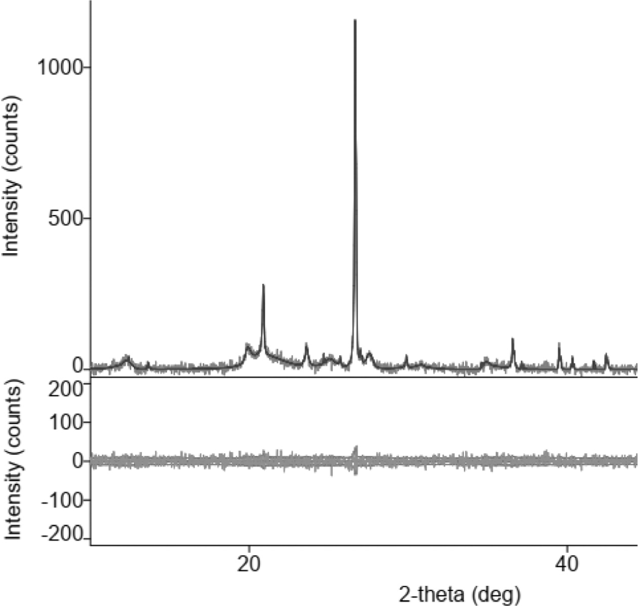
Fig. 1 shows the X-ray diffraction of the organoclay, at
an angle of 2 thetas, between 20-30°, the position of the highest peak of
intensity (> 1000), showing the silica element contained in the
organoclay. The same characteristic graph of clay was also shown by other studies,
[20, 15, 16, 21-23].
Fabrication
of specimens
The coconut coir pyrolysis process is carried out in a
furnace with an airtight tube. Milling is conducted with a crusher to reach a
mesh size of 150; 200; 250; 300; 350, was sieved with a sieve vibrator. Mixing
carbon powder with organoclays for the formation of mixed plasticity, with a
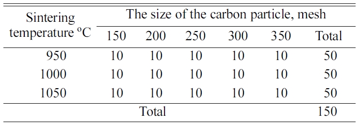
composition ratio of carbon powder and clay mixture designed 30:70, produced 30
green compact specimens. Compaction was carried out with a hydraulic press
machine with a pressure of 200 bar, resulting in
a green compact tablet with a size of 40 mm in diameter ×
10 mm thick. Repyrolysis sintering was carried out in a furnace with an
airtight reactor tube, at temperatures varying from 950; 1000; 1050 oC,
with a temperature velocity of 2 oC/min, carbon-ceramic is
produced with electrically conductive properties. The total specimens are shown
in Table 2.
Electrical
conductivity test
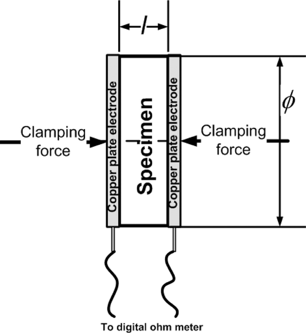
Electrical conductive properties were tested using the
two-point probe method, with a modification of the copper plate electrode
instead of the probe. Measure- ments
were made against the DC electric current resistance
using a digital multitester, specimen diameter, and
thickness of carbon-ceramic specimens. The measure- ment of electrical
conductivity follows the ASTM D257 standard [15, 16, 5, 24, 25]. The testing
method is shown in Fig. 2.
Measurements were made of electrical resistance, specimen
thickness, and cross-sectional area of specimens for
electricity. Electrical static resistance is calculated by the equation,

The amount of electrical conductivity is determined by the
equation,

Note: r = static
electricity resistance [Ωm]; R = electrical resistance [Ω];
A = cross-sectional area of specimens [m2]; l = length
of current path [m]; s = electrical
conductivity of specimens [1/Ωm] or [S/m].
Thermal
Conductivity test
Testing of thermal conductivity to determine thermal
physical properties, especially heat conductivity, of carbon-ceramic to heat
flow. This test refers to the ASTM E1530 standard for evaluating resistance to
thermal transmission of materials through the protected heat
flow meter technique [5]. This test method includes a
steady-state technique in determining resistance to thermal transmission. Two
solid samples were prepared with a diameter of 50 mm and a thickness of
4 mm and 2 mm from each sample.

Note: l and k refer to the thickness of the sample and
thermal conductivity respectively. Subscripts a and b show two different sample
thicknesses.
Wear
resistance test
Wear rate testing is carried out to determine the
resistance of carbon-ceramic to friction using a disc wear tester. Different
studies use the wear resistance test method with the ball-on-disk method [26].
Another study uses the pin-on-disk method, to test the
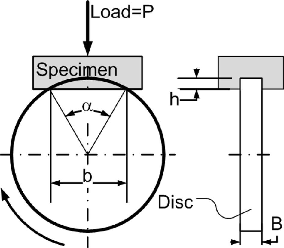
wear rate [27, 28]. In this study, wear rate testing follows ASTM C1243-93
(2015) standards [29, 30], with a disc-wear testing machine. Shown in Fig. 3.
The specific wear rate is calculated by the equation,

Note: Wrate = specific wear rate [mm3/Nm];
b = trace length [mm]; L = distance [m]; P = test
load [N]; r = disk radius [mm]; B = trace
width [mm]; h = trace depth [mm].
Density
test
A density test is conducted to determine the density level
of carbon-ceramic. Another study determined the density by weighing the
specimen weights then divided by the volume of the specimen [14]. This study,
the density test was conducted experimentally using the Archimedes
method based on the ASTM D792 standard [16, 31, 32, 11, 33, 34,
35]. The density of carbon-ceramic is calculated by the equation,

Porosity
test
The porosity test is to determine the percentage of voids
and voids contained in the carbon-ceramic volume. The
porosity test applies the Archimedes method following
the ASTM C20 - 00 (2015) standards [16, 11 33, 36, 37]. Porosity is
calculated as follows,

Note: WA = dry weight [gram]; WB = saturated
weight of water in the air [gram]; WC = saturated
weight of water in the water [gram]; rcomposite
= composite density [g/cm3];
rdistilled
water = the density of distilled water 0.992
[g/cm3]
Morphological
tests
This test was conducted to determine the morpho- logical conditions of carbon-ceramic on a
micro-scale. Based on the morphology of carbon-ceramic, the geometric shape of
the particles can be identified, both matrix and carbon particles, the
interface bond between the particles can be known, and the appearance of
cavities that cause porosity of the ceramic can be identified. Morphological
tests were conducted with Hitachi SU 3500 microscopic scanning electron.
|
Fig. 1 X-Ray Diffractions of organoclay. |
|
Fig. 2 Two plate electrodes testing method. |
|
Fig. 3 Disc-wear testing method. |
Electrical
conductivity
The purpose of measuring electrical conductivity is to
determine the highest electrical conductivity value of carbon-ceramic.
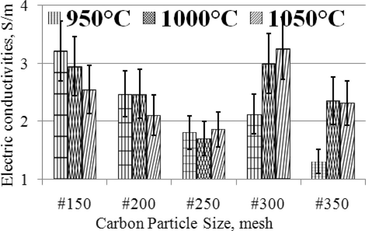
Electrical conductivity values are arranged in
graphical form, as shown in Fig. 4.
The highest electrical conductivity was produced by
specimens with carbon particle size #300, with a sintering
temperature of 1050 oC, an electrical conductivity
value of 3.26 [S/m]. Meanwhile, the lowest 1.31 [S/m] is produced by specimens
with carbon particle size #350 at a sintering temperature of
950 oC. The condition of the specimen with carbon
particle size # 150, when the sintering temperature increases, the electrical
con- ductivity
decreases, also experienced by carbon-ceramic with
particle # 200, whereas for samples with carbon particle # 250, the electrical
conductivity produced is relatively constant. Specimens with particle sizes
#300 and #350, when the sintering temperature is increased it tends to increase
the electrical conductivity of the specimens. In general, at mesh particle size
# 150; 200; 250, the electrical conductivity decreases further, when the
sintering temperature is raised, from 950 oC to 1050 oC.
In specimens with mesh particle sizes # 300 and # 350, and higher sintering
temperatures (from 950 oC - 1050 oC),
this will increase electrical conductivity. Factors
affecting DC conductivity in solids are current carrier concentration,
temperature, defective density and/or structural irregularities, and facilities
where ions can jump to adjacent empty locations [38, 2]. The particles in this
study are small carbon which is homogeneously dispersed which acts as a
conductive phase in the ceramic matrix [24]. The more carbon particles as a
conductor filler, and cling tightly to the ceramic matrix will result in good
interface contact, and this will increase the electrical conductivity the
better. When the carbon content is at the percolation limit, a continuous
electrically conductive path begins to form, that is, an electric current can
flow between adjacent carbon particles through direct contact or tunneling
effects, and so the resistance decreases. The conductor filler network is
formed by the relationship between the conductor fillers that are close
together and stick together. Based on the volume fraction of few-layer
graphene in multilayer composites, it produces electrical
conductivity from 1 × 10-14 to 1 × 10⁻⁴
[S/cm] [25]. Engineering ceramics from clay illite, the results of AC
electrical conductivity tests show values from 1 × 10⁻² to
1 × 10⁻⁷ [S/m] [2]. The electrical properties of the
insulant appear to be very dependent on the chemical and mineralogical
composition of the clay used, and the soaking period used. The study of the use
of clay from Indian Jammu, for insulant ceramics, produces
electrical conductivity of around 0.5 to 2 × 10⁻⁸
[mhos/cm] [39]. The electrical properties of aluminum nitride ceramics show
electrical resistance from 1 × 10¹⁰ to 1 × 10¹⁴
[Ω cm] [40].
Thermal
conductivity
Testing of thermal conductivity to determine thermal
physical properties, especially heat conductivity, of carbon-ceramic to heat
flow. Thermal conductivity testing has also been carried out in other studies,
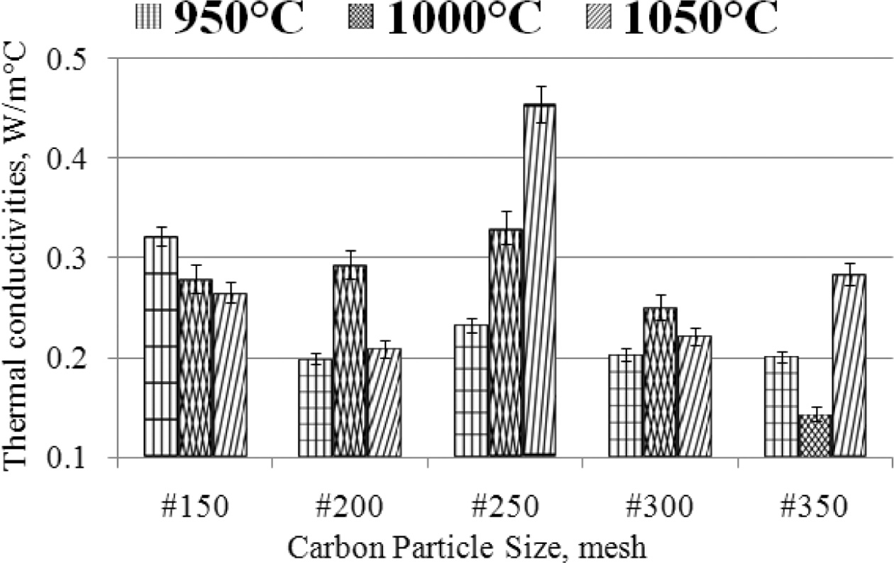
with different methods, [41, 42, 43, 44, 45]. The highest thermal
conductivity is ± 0.45 [W/moC], produced from
specimens with carbon particle size # 250, in the sintering process of
1050 oC. The lowest thermal con- ductivity is ± 0.1 [W/moC],
produced from carbon-ceramic with particle # 350, at sintering temperatures of
1000 oC. This is shown in Fig. 5, the deviation values
of each sample variant are shown, with an average deviation value not higher
than 10%.
The smaller the particle size of carbon, the smaller the
thermal conductivity produced by carbon-ceramic. This occurs at sintering
temperatures of 950 oC and 1000 oC.
Meanwhile, at a sintering temperature of 1050 oC,
indicating that the smaller the particle size, the increase in
thermal conductivity. The effect of sintering temperature
on the thermal conductivity of carbon-ceramic also shows an unequal tendency.
As shown in Fig. 5, the mesh size # 150 shows that the higher the sintering temperature,
the lower the thermal conductivity. Mean-
while, samples with mesh # 200 to mesh # 350 show increased
thermal conductivity, when the sintering temperature is increased from 950 to
1050 oC. In com- parison, other studies have also produced
thermal con- ductivity, which is shown
as follows. Allegreta studied the thermal conductivity
values of kaolin samples with kaolinitic clay
(kaolinite = 58%, ilite = 18%, smectite = 2%,
quartz = 22%, rutile and anatase in the trace). The highest thermal
conductivity value is ± 0.68 [W/mK] produced by kaolin samples with
tempering tempera- tures up to
1000 oC, and the lowest is ± 0.28 [W/mK] [46]. The raw
material used in this study is kaolin powder which is marketed by the company
Denain-Anzin-Minéraux (France). When the temperature inc- reases, the
sintering process implies better material consolidation
due to the decomposition of clay particles in the
mullite phase and amorphous flux which is rich in silica. This study produced a
thermal conductivity of 0.28 to 0.63 [W/mK] [47]. The clay-based ceramics
investigated in this study were made of clay, sand, and water. Clay is
extracted as a batch in a clay mine to ensure
homogeneity. Clay-based ceramics produce thermal
conductivity of 1.07 [W/mK] [43]. Three commercially available soil-based
plasters, widely used for interior wall base systems in several European
countries, selected for experimental testing. The thermal conduc- tivity of the sample disk made from the soil
plaster material examined is measured. This study yields thermal conductivity
of 0.74 to 1.16 [W/mK] [48]. The clay material supplied by Ceradel company
(Saint Amand en Puisaye, France) is a mixture of extruded clay that is used for
making pots. To ensure good homogeneity, the raw material is first mixed in
water. This study yields thermal conductivity of ± 0.4 to 1.8 [W/mK] [49].
Clay-based materials which exhibit high pore volume fractions and low thermal
conductivity suitable for thermal insulation have been studied. This study
shows a thermal conductivity of 0.063 to 0.130 [W/mK] [44].
Specific
wear rate
Wear rate testing is performed with a disc wear tester, by
measuring the variables of wear depth, wear trail length, wear trail width,
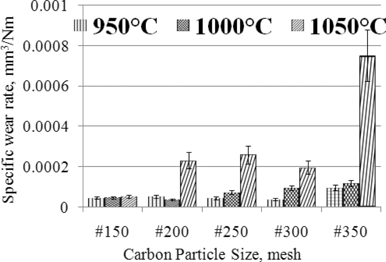
load, rotational speed, distance traveled. The lowest wear rate is produced by
carbon-ceramic with carbon particle size # 200, at a sintering temperature of
1000 oC, which is 3.59827 × 10-05 [mm3/Nm],
in this condition this material shows the highest hardness compared
to other specimens, of the size different carbon particles.
The softest specimens in this study produced the highest wear rate, 0.000752239
[mm3/Nm], this was demonstrated by specimens with carbon particle
size #350, at sintering temperatures of 1050 oC, as shown in
Fig. 6. The graph shows that the higher the sintering temperature the higher
the wear rate produced, the condition shows that the increase in sintering
temperature tends to decrease the wear resistance properties, in other words,
the softer the specimens. Carbon-ceramic tend to show relatively stable wear
rates at particle size # 150, even though the sintering temperature is raised
to 1050 oC. This specimen shows the harshest
mechanical character. Likewise, the smaller the particle
size of carbon powder tends to increase the wear rate, meaning that
carbon-ceramic is softer, and is not resistant to mechanical friction. Wear
rate is one of the mechanical properties of carbon-ceramic; this mechanical
property can also represent the level of hardness of the material.
Indirectly can also show the level of strength of the
carbon-ceramic. The concept is, the lower the wear rate, the higher the level
of hardness of the ceramic, and thus the higher the tensile strength of the
specimens, with the structure of the material being isotropic. As in this study,
this carbon-ceramic is designed isotropic, therefore using
powder-shaped filler. The weakness of the mechanical properties of this
material is thought to be caused by porous cavities formed in carbon-ceramic,
although the fabrication process of carbon-ceramic tablets applies a pressure
of 200 bars, with a hydraulic press.
Allegedly, when printing green compact, there are air
cavity bubbles trapped inside, so that during the sintering process the air
cavity forms porous in a carbon-ceramic. Some elements of the organoclay are
thought to have also burned during the high-tem- perature sintering process; this will form a
porous in the material. As explained in the analysis of relation- ships of porosity and composite wear rates.
This study tested the wear rate using the two-body abrasive wear test method,
which was carried out using a pin on disc tool. This study shows the wear rate
based on weight loss from the material being tested [29]. Other
researchers applied specific wear rate testing to the ASTMG99-95a
standard producing specific wear rates with values from
5 × 10⁻⁷ to 1.5 × 10⁻⁵ [mm3/Nm]
[50]. The wear rate of the C/C-SiC composite produces a specific rate
of 2.5 × 10⁻⁴ to 5 × 10⁻⁴ [mm3/Nm]
[51]. The engineering of carbon-ceramic composites from other studies shows
testing the wear rate based on the level of hardness of the composite [28].
Carbon-ceramic
density
Density testing is carried out to determine the level of
density of carbon composites. This test was carried out experimentally using
the Archimedes method based on the ASTM D792 standard [30, 34, 35, 37]. The
condition of the density will indicate the degree of porosity of the specimens.
The lower the densities level of the carbon-ceramic, the
higher the porosity of the specimens.
This will affect the level of electrical conductivity and
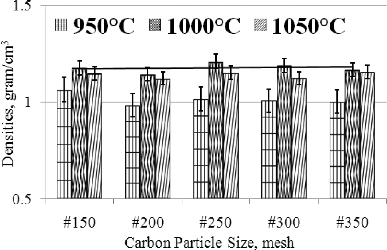
ceramic wear resistance. The density of carbon-ceramic is arranged in graphical
form as shown in Fig. 7. The engineering of carbon-ceramic shows the physical
properties of relatively stable densities between 1-1.2
[gram/cm3]. In detail, it can be proven that there is an increase in
density when the sintering temperature is increased, but an increase in density
of about 0.2 [gram/cm3], when observing the deviation value, the
value of increasing density is not significant. Changes in carbon particle size
from #150 - #350 also do not make significant changes in densities.
As shown in Fig. 7. The smaller the particle size of carbon, the density is
relatively unchanged. As a comparison to the results of other studies,
explained as follows. This researcher utilizes kaolin for compacting and
sintering with temperature variations from 980 - 1200 oC,
producing densities of 2.55 to 2.9 [grams/cm3], and porosity of 6.3
to 35.4% [47]. A study of ceramics fabricated from kaolin,
bentonite, and sand. To investigate the evolution of
electrical resistivity of various layers of kaolinite dominant clay, in terms
of soil composition, due to moisture content and dry density
changes. This research resulted in a composite density
between 0.72 to 1.87 [gram/cm3] [52]. A
carbon-ceramic composite fabricated from fly ash,
carbon fiber, and other particles, compacted 200
[kg/cm2], heated to 1000 oC, has produced densities
between 1.65 to 1.87 [gram/cm3] [28].
Carbon-ceramic
porosity
The porosity test applies the Archimedes method following
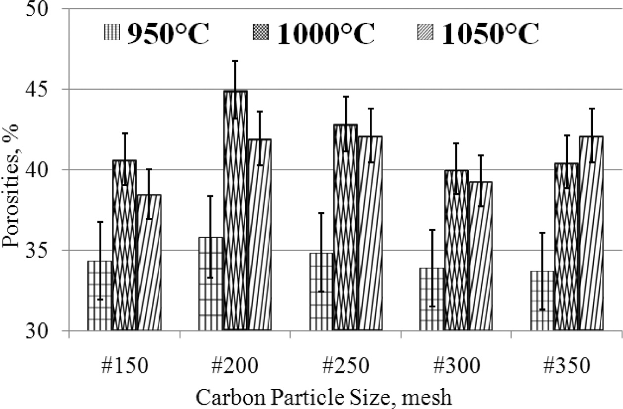
the ASTM C20 - 00 (2015) standards [16, 11, 33, 37]. Carbon-ceramic
shows relatively high porosity, between 33 - 42%
porosity. Based on considera- tion
of the deviation of carbon-ceramic in the 950 oC sintering
process shows the percentage of porosity that is relatively stable, between
33 - 36%, even though the particle size gets smaller, from mesh #
150 - # 350, while carbon-ceramic with the same mesh particle size (#
150 - # 350) which is processed by sintering 1000 oC,
producing porosity between 40 - 45%, while carbon-ceramic processed
by sintering at temperatures of 1050 oC show porosity between
38 - 42%, with a mesh size change of # 150 - # 350. The
porosity of carbon-ceramic is even greater when the sintering process
temperature is raised from 950 - 1050 oC, with an
equal composition ratio of 70: 30%, as shown in Fig. 8. This condition is
thought to be due to the fact that most organoclay matrices turn to carbon when
sintering is processed at high temperatures. This increases the volume of
carbon in the carbon-ceramic, and carbon has a high absorption of water when
testing porosity.
Broadly speaking, the smaller the size of carbon particles
in carbon-ceramic, the porosity contained by carbon-ceramic
is relatively stable, there is no significant change. In
comparison, several researchers, using the same method, produced the porosity
described below. Because the particles grow irregularly, the ability of the
particles to bear the external force decreases when an external load is
applied. The compressive strength of the sample is reduced due to an increase
in porosity, which is caused by a pile of compressed particles between the
particles, this study produces a porosity of 70 to 80%
[53]. Another study showed the real porosity of the K1
and K2 specimens calculated according to the Archimedes principle, each
equivalent to 21.9 and 19.9%. Thus, round silica solids show lower porosity,
that is, denser microstructure [36]. This study shows the results of porosity
testing of various types of ceramic specimen particle sizes and produces
porosity between 14 to 43% [54]. This researcher utilizes bentonite as a
mixture for clay and silica ceramics producing porosity from 10 to 50% [37].
The
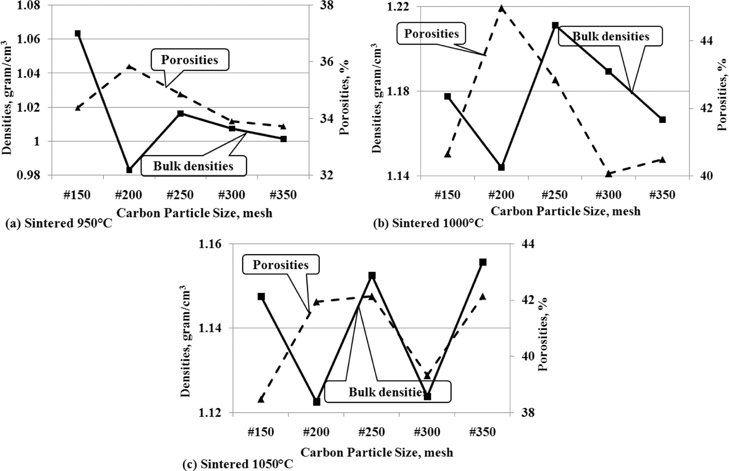
relationship of density to porosity
This analysis is to show the interdependence between density
and porosity. The concept which states that when density increases, porosity
will decrease, does not apply significantly in the facts of this study. Figure
9 (a); 9 (b); and 9 (c) show that when the carbon particle size gets smaller
the density shows a decrease, followed by a decrease in the percentage of
porosity volume. This occurs relatively similarly at all sintering temperatures.
Fig. 9 (a) shows the same tendency between density and
porosity of carbon-ceramic composites which are processed by sintering at
950 oC.
The fact that relatively similar trends are also shown by
carbon-ceramic by sintering at temperatures of 1000 oC, as
shown in Fig. 9 (b), when the size of carbon particles decreases, the density
also decreases and is followed by decreasing porosity. The same relative thing
is also shown in Fig. 9 (c), the density increases and is followed by increased
porosity as well, at the particle size reduction of mesh #150 - #350, at a
sintering temperature of 1050 oC. The fact that happens is,
porosity tends to follow density, even though the size of carbon particles gets
smaller.
The
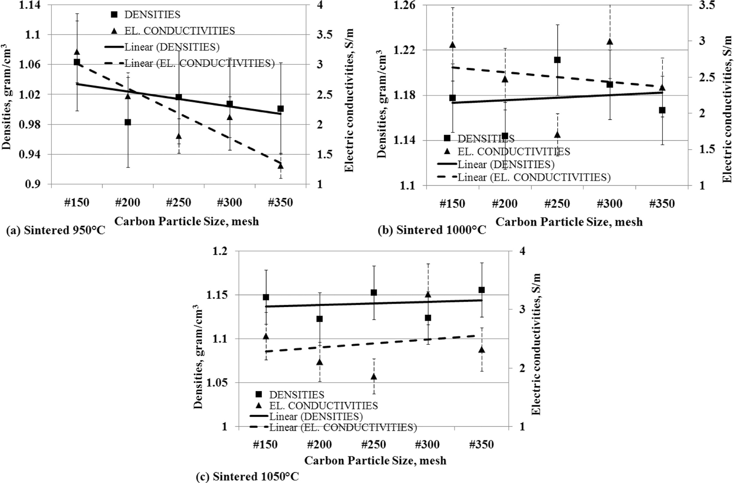
effect of the density to electrical conductivity
Density is a physical property that shows a specific level
of material weight in units of volume, it can be named density. The fact that
occurs in the fabrication of carbon-ceramic shows that the density affects the
electrical conductivity, as shown in Fig. 10. Fig. 10 (a) is a fact of
carbon-ceramic with a sintering process at a temperature
of 950 oC, which shows the smaller particle
size carbon spread in the specimens makes electrical conductivity decreases,
following the decrease of the density.
Carbon-ceramic with a 1000 oC sintering
process shows a different fact, the smaller the size of carbon particles,
indicating an increase in the density of the carbon-ceramic, but conversely,
the electrical conduc- tivity actually
decreases, as shown in Fig. 10 (b). The decrease in carbon particle size in the
specimens gives an increase in the density of the carbon-ceramic and is
followed by an increase in electrical conductivity shown by carbon-ceramic by
sintering at temperatures of 1050 oC, as shown in Fig. 10 (c).
In general, an increase or decrease in carbon-ceramic density based on carbon
particle size is followed by an increase or decrease in
the electrical conductivity of carbon-ceramic.
The
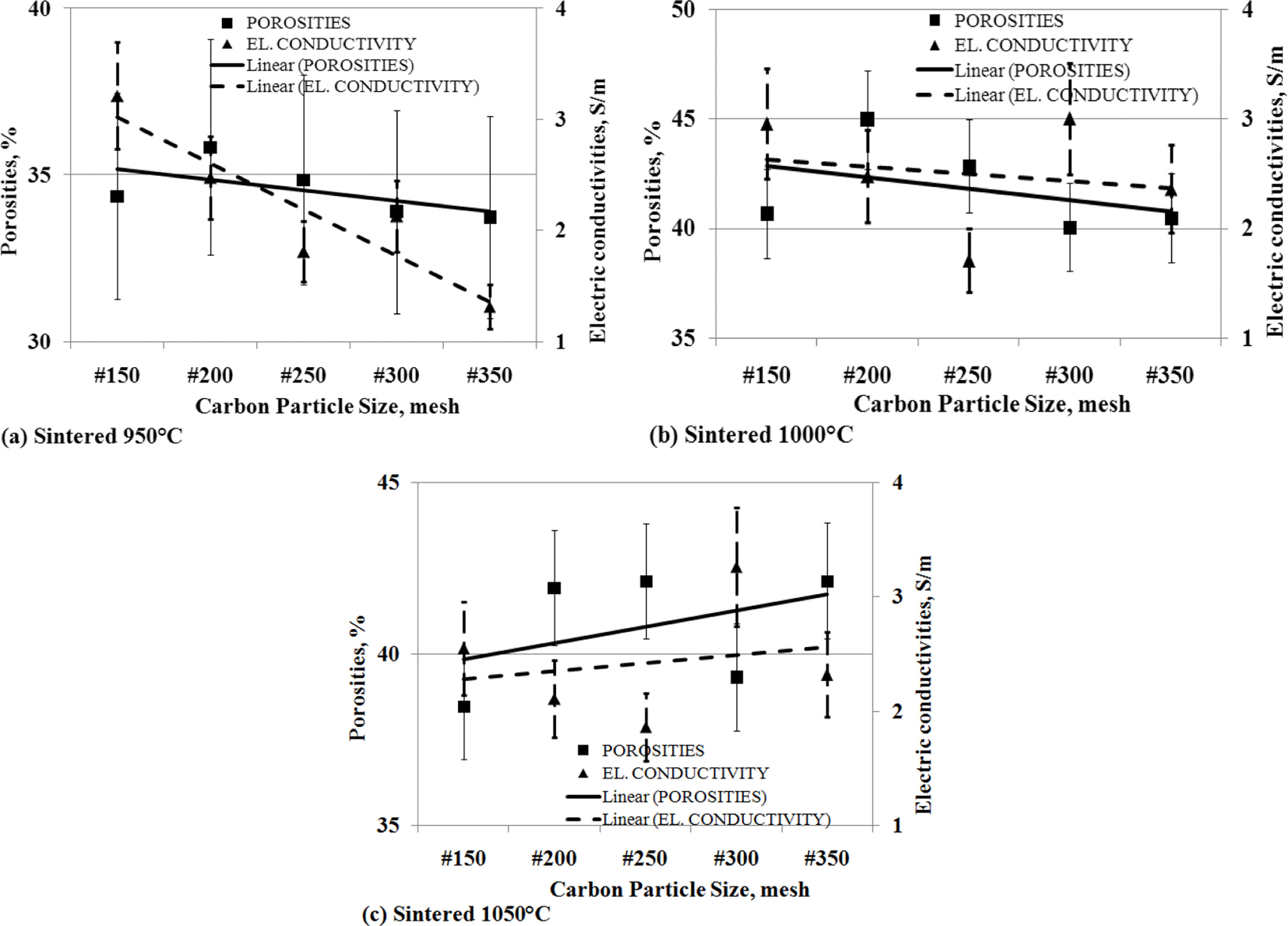
effect of the porosity to electrical conductivity
The level of porosity of carbon-ceramic will affect the
level of electrical conductivity.
Porosity is cavities formed in ceramic due to compaction.
Cavities formed on carbon-ceramics cause connectivity between carbon
conductivity particles to be disrupted and become a barrier to the flow of electricity.
This study shows that the smaller the change in the
particle size of carbon powders, the lower the porosity volume of
carbon-ceramics followed by a decrease in electrical conductivity.
This is experienced by carbon-ceramic at sintering
temperatures of 950 oC, as shown in Fig. 11 (a). Likewise,
carbon-ceramic with a sintering temperature of 1000 oC
experienced the same decrease between the porosity volume and the electrical
conductivity of the specimens, as shown in Fig. 11 (b). Different charac- teristics are shown in carbon-ceramic with
sintering temperatures of 1050 oC, the smaller the particle
size of carbon, the greater the percent porosity volume, and followed by an
increase in electrical conductivity of carbon-ceramic. This is shown in Fig. 11
(c).
The
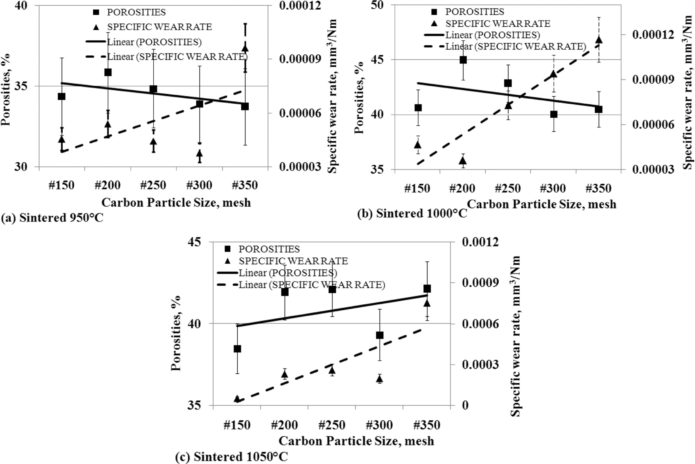
effect of porosity to specific wear rates
Cavities are formed in carbon-ceramics, which weaken the
mechanical bonding of filler particles and matrix particles, and between filler
particles and matrices. This fact is shown in Fig. 12. Theoretically, when the
percentage of porosity increases, it will form a weak bond between the
particles, producing a weak bond mechanically. The greater porosity percentage
indicates the number of cavity volumes in the specimen more and more, and the
bond between particles is mechanically weaker, so the wear rate gets higher, or
carbon-ceramic becomes softer, hardness decreases and easily wears out.
Conversely, a small percentage of porosity indicates a small number of cavities
in carbon-ceramics, and increases mechanical bonding between particles, both
fillers, matrices, and between matrices and fillers,
and thus strengthens the mechanical properties of these
specimens. This research does not always show the similarity of characteristics
with theoretical concepts. Carbon-ceramic with a sintering temperature of
950 oC shows the opposite character.
When the particle size of the carbon powder gets smaller,
resulting in a smaller percentage of porosity, but vice versa is followed by an
increase in higher wear rates, which means that this type of specimen exhibits
weaker mechanical bonding properties, its hardness decreases, as shown in Fig.
12 (a). Likewise, the characteristics shown by carbon-ceramics by the sintering
temperature process of 1000 oC, show the same character, this
is shown in Fig. 12 (b). Different characters are shown by carbon-ceramic with
sintering temperatures of 1050 oC, shown in Fig. 12 (c). The
study shows, the smaller the particle size of carbon powders results in greater
porosity percentages and is followed by the higher wear rate of the specimens.
This fulfills the concept that the more cavities in the carbon-ceramic will
weaken the mechanical bonding properties of the materials, and thus weaken the
mechanical properties, increasing the wear rate of carbon-ceramic.
The
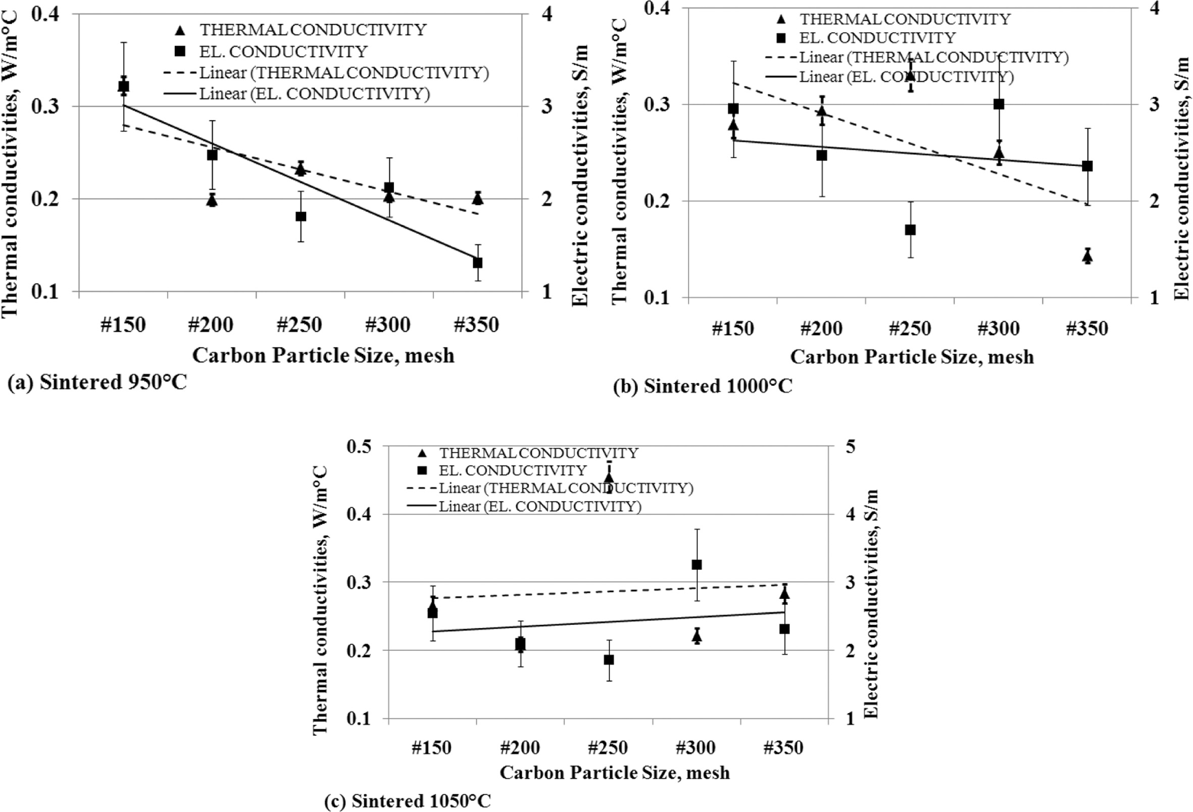
relationship of thermal conductivity to the electric conductivity
Thermal conductivity has a relationship with electrical conductivity.
When thermal conductivity decreases, it is followed by reduced electrical
conductivity.
This is shown in Fig. 13 (a) and (b), which are produced
from carbon-ceramic with sintering temperatures of 950 oC and
1000 oC. The smaller the particle size of carbon, the value of
thermal and electrical conductivity decreases. Carbon-ceramic with the
sintering process of 1050 oC produces different tendencies, as
shown in Fig. 13 (c). The figure shows that the smaller the particle size of
carbon, the more thermal and electrical con-
ductivity increases. Based on the facts of the analysis, the tendency of
thermal conductivity will be followed by the tendency of electrical
conductivity.
Morphology
of carbon-ceramic
Microphotographs from the scanning electron micro- scopic test cannot distinguish morphology
based on the ratio of composition between carbon and organoclay and also based
on sintering temperature, this test will show the size of carbon particles
scattered in the ceramic matrix of organoclays. The test was carried out with a
Hitachi SU 3500 scanning electron microscopic testing machine. The purpose of
this test is to look at the morphological state of carbon-ceramic. To see the
possibility of cavity formation on the specimens and the interface bond between
organoclay and carbon powder from coconut coir powder. Cavities formed in the
specimens will weaken the electrical conductivity and wear
resistance of the carbon-ceramic. Morphological are shown
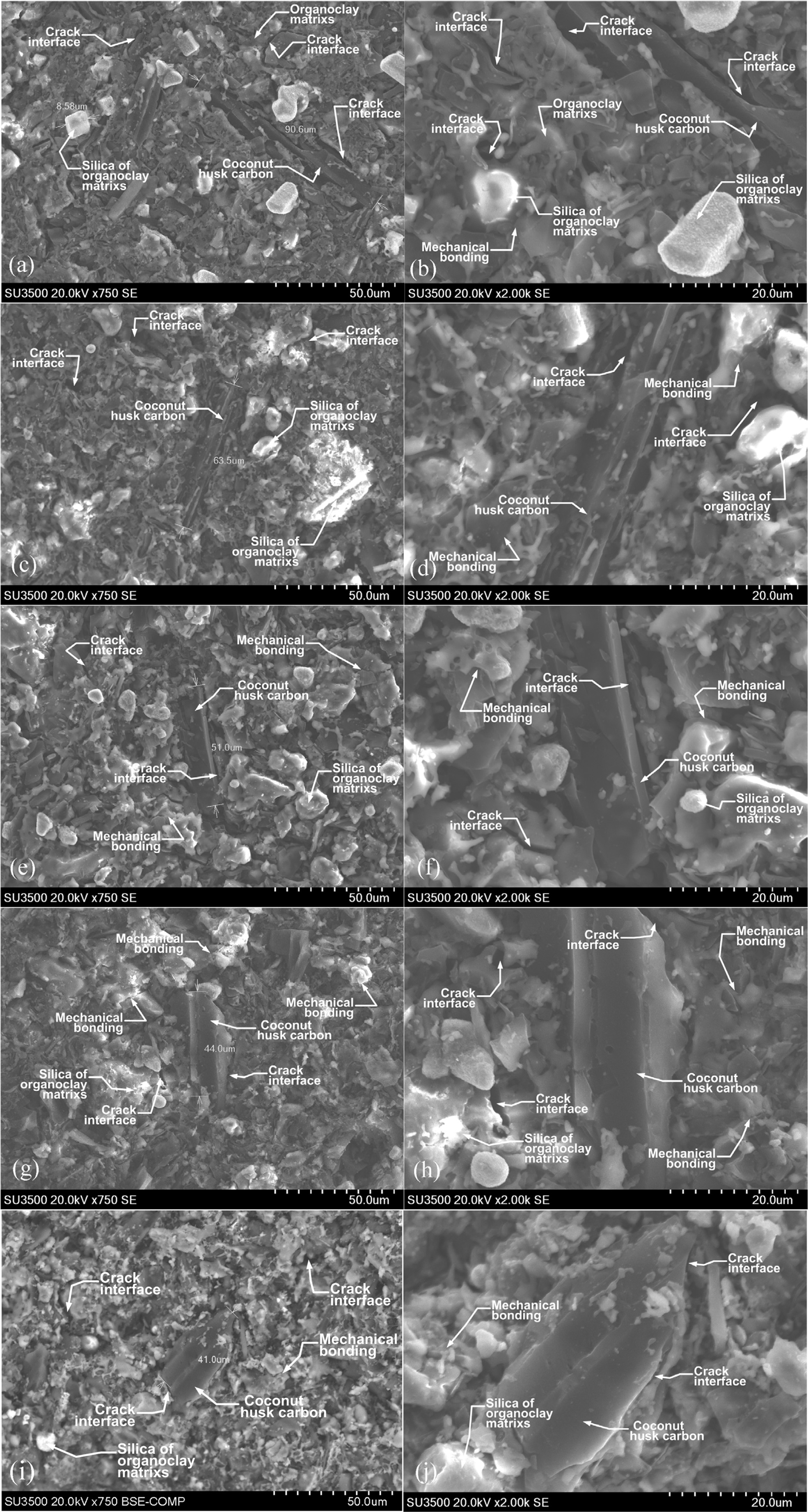
in Fig. 14 (a) to 14 (j). The shape and geometric carbon powder, in general, is
elongated and irregular, and not granule or round in shape. The size of the
carbon powder is shown in the elongated micron size, 90 μm, shown by
carbon-ceramic with mesh size # 150, as shown in Fig. 14 (a). Based on the ASTM
wire mesh standard, the 90 μm particle size is relevant to the standard
mesh size number between 140 to 170. Fig. 14 (a) and (b) with magnifications of
750 and 2000 also shows the interface cracks between carbon particles
against organoclay matrix particles, silica particles from
organoclay matrices, mechanical bonding between particles
are also shown in the carbon-ceramic morpho-
logy. The smaller carbon particle size is shown in Fig. 14 (c), the
figure is the morphology of carbon-ceramic with carbon particle size # 200,
with an elongated particle size of 63.5 µm this particle size is relevant
to the ASTM standard wire mesh sieve chart numbers between 200 to 230. In
general, shapes and geometric carbon particles are elongated and irregular in
shape, and have dark features, as shown in Fig. 14 (c) and (d), with
magnifications of 750 and 2000. Also shown in the picture are silica particles
from the organoclay matrix, that are shown with bright white features, cracks
interface between carbon particles against the matrix, between particles of the
matrix, mechanical bonding between matrix and carbon particles. Carbon-ceramic
with mesh # 250 shows elongated geometric carbon particles measuring
51 µm. This dimension is relevant to the ASTM wire mesh standard between
numbers 270 to 325. At magnifications 750 and 2000, shown in Fig. 14 (e) and
(f) is the morphology of the interface cracks between carbon particles against
orga- noclay matrix particles, silica
particles of the matrix, mechanical bonding between particles.
The morphology of carbon-ceramic particles with mesh size # 300
is shown in Fig. 14 (g) and (h), at magnifications of 750 and
2000. The morphology shows the irregular geometric shape
of particles, both carbon particles, and organoclay matrix
particles. The measurement results of carbon particles show 44 μm, this is
relevant to the ASTM standard wire mesh sieve chart between numbers 325 to 400.
Interface cracks between carbon particles against the organoclay matrix are
also shown in the figure. The bright white feature indicates the content of
silica particles from the organoclay matrix. While the dark, irregular, and
elongated black features indicate carbon particles, or it is also suspected to
be very strong is the crack or porous of the specimens. The morphology of
carbon-ceramic with mesh size # 350 shows the carbon particle size of 41 μm, as
shown in Fig. 14 (i). The carbon particle size is relevant to the ASTM sieve
chart standard wire numbers between numbers 325 to 400. Fig. 14
(i) and 14 (j) show geometric irregular carbon particles and
matrices, showing mechanical bonds between particles, showing the interface
cracks between filler particles and matrices. The white and bright features in
the morphology indicate the silica content of the organoclay matrix. Meanwhile,
the dark morphological features indicate carbon particles and a very strong
suspicion is cracks or porous that occurs within the carbon-ceramic. This study
shows that compaction load of 200 bars and with smaller particle size apparently
cannot eliminate porous or cracks that occur in the specimens. The strong
suspicion of porous and cracking is caused more by the irregular shape of
carbon particles and matrix particles.
The cavities formed are also thought to be a result of the
heating process in the sintering process, the particles forming the
carbon-ceramic bonds have non-uniform volume expansion coefficients, resulting
in pressing on each other and cracking even weaker particles mechanically. It
is also suspected that bonding between particles is only mechanical in nature,
relying only on the irregularity of the pairs of particles.
|
Fig. 4 The relationship of electric conductivities vs. carbon particle size vs. sintering temperature. |
|
Fig. 5 The relationship of thermal conductivity vs. carbon particle size vs. sintering temperature. |
|
Fig. 6 The relationship of specific wear rate vs. carbon particle size vs. sintering temperature. |
|
Fig. 7 The relationship between densities vs. carbon particle size vs. sintering temperature. |
|
Fig. 8 The relationship of porosities vs. carbon particle size vs. sintering temperature. |
|
Fig. 9 The relationship between densities vs. porosities vs. carbon particle size. |
|
Fig. 10 The relationship between densities vs. electric conductivities vs. carbon particle size. |
|
Fig. 11 The relationship of porosities vs. electric conductivities vs. carbon particle size. |
|
Fig. 12 The relationship of porosities vs. specific wear rate vs. carbon particle size. |
|
Fig. 13 The relationship of thermal conductivity vs. carbon particle size vs. electric conductivity. |
|
Fig. 14 Morphology of carbon-ceramic composite. |
At the carbon particle size of mesh #150; 200; 250, the
electrical conductivity decreases, when the sintering temperature is raised,
from 950 oC to 1050 oC. In mesh particle sizes
# 300 and # 350, and higher sintering temperatures (from 950 oC - 1050 oC),
this will increase electrical conductivity. The tendency of thermal con-ductivity follows the tendency
of electrical conductivity, from the effect of carbon particle
size. The higher the sintering temperature the higher the wear rate pro-duced, this condition shows
that the increase in sintering temperature
tends to decrease the wear resistance pro-
perties, in other words, the softer the carbon-ceramic. Likewise,
the smaller the particle size of carbon powder tends to
increase the wear rate, meaning that carbon-ceramic is softer, and is not
resistant to mechanical friction. The smaller the particle size of carbon, the density
of carbon-ceramic composites that occur relatively no change.
In general, the smaller the size of carbon particles in carbon-ceramic, the
porosity of carbon-ceramic is relatively stable. There is no significant
change. In fact, porosity tends to follow density, even though the size of
carbon particles gets smaller. In general, an increase or decrease in density
due to carbon particle size is followed by an increase or decrease in the
electrical conductivity of carbon-ceramic. Compaction of
200 bar and with smaller particle size apparently can not
eliminate porous or cracks that occur in the specimens. The occurrence of
porous and cracking is more due to the irregular shape of carbon particles
and matrix particles. Bonding between particles is only
mechanical in nature, relying only on the irregularity of the pairs of
particles.
The DIPA of Politeknik Negeri Jakarta, Scheme of the
Leading of Study Program Research has funded this study, Contract Number: 350 /
PL3.18 / PN.00.03 / 2019, Fiscal Year 2019.
The author thanks P3M, Politeknik Negeri Jakarta.
- 1. I. Štubňa, T. Húlan, T. Kaljuvee, and L. Vozár, Appl. Clay Sci. 153 (2018) 23-28.
-

- 2. Š. Csáki, J. Ondruška, V. Trnovcová, I. Štubňa, P. Dobroň, and L. Vozár, Appl. Clay Sci. 157 (2018) 19-23.
-

- 3. S. Ojha, S.K. Acharya, and G.J. Raghavendra, Appl. Polym. Sci. 132[1] (2015) 1-7.
-

- 4. M. Yates, M.A. Martín-luengo, L.V. Argomaniz, and S.N. Velasco, Microporous Mesoporous Mater. 154 (2012) 87-92.
-

- 5. A.E. Pramono, M.B.T. Firdaus, W. Ratriomasyo, M.Z. Nura, and J.W.M. Soedarsono, J. Ceram. Process. Res. 18[10] (2017) 748-753.
- 6. Y. Yao, B. Gao, J. Fang, M. Zhang, H. Chen, Y. Zhou, A. E. Creamer, Y. Sun, and L. Yang, Chem. Eng. J. 242 (2014) 136-143.
-

- 7. Y. He, L. Lu, S. Jin, and S. Hu, Constr. Build. Mater. 53 (2014) 131-137.
-

- 8. Z. Terzopoulou, D. Bikiaris, K.S. Triantafyllidis, G. Potsi, D. Gournis, G.Z. Papageorgiou, and P. Rudolf. Thermochim. Acta 642 (2016) 67-80.
-

- 9. T. Gumula, A. Rudawski, J. Michalowski, and S. Blazewicz, Ceram. Int. 41[6] (2015) 7381-7386.
-

- 10. M.S. Amin, S.M.A. El-gamal, and F.S. Hashem, Constr. Build. Mater. 98 (2015) 237-249.
-

- 11. R.L. Menchavez, M. Fuji, T. Shirai, and T. Kumazawa, J. Eur. Ceram. Soc. 34[3] (2014) 717-729.
-

- 12. C. Maurício, R. Sanchez, S.N. Monteiro, N. Lalla, and N. Quaranta, J. Mater. Res. Technol. 2[2] (2013) 88-92.
-

- 13. B. Han, L. Zhang, C. Zhang, Y. Wang, X. Yu, and J. Ou. Constr. Build. Mater. 125 (2016) 479-489.
-

- 14. 14. A. Wang, X. Gao, R.F.G. Jr, and D.D.L. Chung, Carbon N. Y. 59 (2013) 76-92.
-

- 15. A.E. Pramono, M. Zaki, J. Wahyuadi, M. Soedarsono, and N. Indayaningsih, J. Ceram. Process. Res. 20 (2019) 1-7.
-

- 16. A.E. Pramono, M.Z. Nura, J.W.M. Soedarsono, and N. Indayaningsih, J. Ceram. Process. Res. 20[4] (2019) 333-346.
-

- 17. V. Mymrin, C.F.G. Santos, K. Alekseev, M.A. Avanci, M.A. Kreusch, T. Borga, O. Graupmann, F.L. Cavalin, R.A. Monteiro, and V.A. Ruy Federal. Appl. Clay Sci. 155 (2018) 95-102.
-

- 18. F. Pardo, M.M. Jordan, and M.A. Montero, Appl. Clay Sci. 157 (2018) 158-164.
-

- 19. Z. Li, H. Zhang, P. Zhao, X. He, and X. Duan. J. Korean Ceram. Soc. 55[1] (2018) 36-43.
-

- 20. A. Mocciaro, M.B. Lombardi, and A.N. Scian, Appl. Clay Sci. 153 (2018) 90-94.
-

- 21. F.O. Aramide and A.P. Popoola, J. Ceram. Process. Res. 19[2] (2018) 87-94.
- 22. N. Belmokhtar, H.E. Ayadi, M. Ammari, and L.B. Allal, Appl. Clay Sci. 162 (2018) 1-9.
-

- 23. A. Miras, E. Galán, I. González, A. Romero-Baena, and D. Martín, Appl. Clay Sci. 161 (2018) 176-183.
-

- 24. Y. He, L. Lu, S. Jin, and S. Hu, Constr. Build. Mater. 53 (2014) 131-137.
-

- 25. K.B. Choi, J.Y. Kim, S.M. Lee, K.H. Lee, and D.H. Yoon, J. Korean Ceram. Soc. 54[3] (2017) 257-260.
-

- 26. W. Sun, P. Zhang, K. Zhao, M. Tian, and Y. Wang, Wear 342-343 (2015) 172-180.
-

- 27. G. Zheng, J. Zhao, and Y. Zhou, Wear 290-291 (2012) 41-50.
-

- 28. L.M. Manocha, G. Prasad, and S. Manocha, Mech. Adv. Mater. Struct. 21[3] (2014) 172-180.
-

- 29. N.C. Kaushik and R.N. Rao, Tribiology Int. 103 (2016) 298-308.
-

- 30. A.E. Pramono, J. Mater. Sci. Eng. B 3 (2013) 700-706.
-

- 31. D.S. Kim, J.S. Kim, and C.I. Cheon, J. Korean Ceram. Soc. 53[2], (2016) 162-166.
-

- 32. H.P.A. Alves, J.B. Silva, L.F.A. Campos, S.M. Torres, R.P.S. Dutra, and D.A. Macedo. Ceram. Int. 42[16] (2016) 19086-19090.
-

- 33. D.O. Obada, D. Dodoo-Arhin, M. Dauda, F.O. Anafi, A.S. Ahmed, and O.A. Ajayi, Appl. Clay Sci. 150 (2017) 175-183.
-

- 34. Z. Hongxia, D. Yongsheng, Y. Xiaowei, O. Shunli, and L. Baowei, J. Ceram. Process. Res. 18 (2017) 604-610.
- 35. C.H. Ting, S. Ramesha, C.Y. Tan, N.I. Zainal Abidin, W.D. Teng, I. Urriés, and L.T. Bang, J. Ceram. Process. Res. 18[8] (2017) 569-574.
- 36. J. Park, J.G. Yeo, S. Yang, and C.H. Cho, J. Ceram. Process. Res. 19 (2018) 20-24.
- 37. S.H. Mahdi, I.A. Hamad, and A.M. Ibraheim, Mesopotamia Environ. J. Mesop. 17 (2016) 10-17.
- 38. J. Ondruška, Š. Csáki, V. Trnovcová, I. Štubňa, F. Lukáč, J. Pokorný, L. Vozár, and P. Dobroň. Appl. Clay Sci. 154 (2018) 36-42.
-

- 39. S.N. Khosla, R.K. Bedi, and C.S. Gupta, Trans. Indian Ceram. Soc. ISSN 5456 (2014) 8-12.
-

- 40. J.-W. Lee, W.-J. Lee, and S.-M. Lee, J. Korean Ceram. Soc. 53[6] (2016) 635-640.
-

- 41. Y.K. Seo, Y.W. Kim, T. Nishimura, and W.S. Seo, J. Eur. Ceram. Soc. 36[15] (2016) 3755-3760.
-

- 42. Y.K. Seo, Y.W. Kim, K.J. Kim, and W.S. Seo, J. Eur. Ceram. Soc. 36[16] (2016) 3879-3887.
-

- 43. P.M. Nigay, T. Cutard, and A. Nzihou, Ceram. Int. 43[2] (2017) 1747-1754.
-

- 44. J. Bourret, A. Michot, N. Tessier-Doyen, B. Nait-Ali, F. Pennec, A. Alzina, J. Vicente, C.S. Peyratout, and D.S. Smith, J. Am. Ceram. Soc. 97[3] (2014) 938-944.
-

- 45. I. Allegretta, G. Eramo, D. Pinto, and A. Hein, Appl. Clay Sci. 135 (2017) 260-270.
-

- 46. I. Allegretta, G. Eramo, D. Pinto, and A. Hein, Thermochim. Acta 581 (2014) 100-109.
-

- 47. D. Buncianu, N. Tessier-Doyen, F. Courreges, and J. Absi, Eur. J. Environ. Civ. Eng. 21 (2017) 1270-1284.
-

- 48. L. Randazzo, G. Montana, A. Hein, A. Castiglia, G. Rodonò, and D.I. Donato, Appl. Clay Sci. 132-133 (2016) 498-507.
-

- 49. J. Bourret, N. Tessier-doyen, R. Guinebretiere, E. Joussein, and D.S. Smith, Appl. Clay Sci. 116-117 (2015) 150-157.
-

- 50. Y.P. Delgado, M.H. Staia, O. Malek, J. Vleugels, and P. De Baets, Wear 317[1-2] (2014) 104-110.
-

- 51. G. Byeong-Choon and C. In-Sik, Materials (Basel). 10[7] (2017) 701.
-

- 52. Q.A. AL Rashid, H.M. Abuel-Naga, E.C. Leong, Y. Lu, and H. Al Abadi, Appl. Clay Sci. 156 (2018) 1-10.
-

- 53. Z. Chu, C. Jia, J. Liu, R. Ding, and G. Yuan, J. Ceram. Sci. Technol. 8[4] (2017) 499-504.
- 54. B.M. Bishui and J. Prasad, Trans. Indian Ceram. Soc. (2014) 109-115.
-

 This Article
-
2020; 21(4): 465-478
Published on Aug 30, 2020
- 10.36410/jcpr.2020.21.4.465
- Received on Feb 19, 2020
- Revised on Mar 22, 2020
- Accepted on Mar 24, 2020
 Services
- Abstract
introduction
experiments
result and discussion
conclusion
- Acknowledgements
- References
- Full Text PDF
Shared
 Correspondence to
- Agus Edy Pramono
-
Department of Mechanical Engineering, Politeknik Negeri Jakarta, Jln. Prof. Dr. G.A. Siwabessy, Kampus UI. Depok 16425, Jawa-Barat, Indonesia
Tel : +62 811 829 833 or +62 217863530
Fax: +62 217863530 - E-mail: agus.edypramono@mesin.pnj.ac.id


 Copyright 2019 International Orgranization for Ceramic Processing. All rights reserved.