- Study on NOx reduction capacity of catalytic coated cordierite monolith
Rekha Durairaja,*, Neelakrishnan Subramanyana and Divakar Duraiswamyb
aDepartment of Automobile Engineering, PSG College of Technology, Coimbatore, TN 641004, India
bDepartment of Chemistry, PSG College of Technology, Coimbatore, TN 641004, India
Legislation world-wide imposes
stringent emission norms, particularly EURO V and beyond. In this regard,
extensive research is being conducted for improving the existing filter design,
material properties and developing alternative design, materials, testing
procedures for more sensitive to reduce NOX values. Cordierite
ceramics are
having good chemical and electrical properties like high
thermal resistance,
low dielectric
constant, low thermal expansion coefficient, and high chemical and mechanical
stability, which makes it for many industrial applications like manufacturing
of the thermal insulation materials, optoelectronic devices, plasma display
panels, solar panels, catalytic convertors etc. In this work, a pair of
cordierite monolith with catalyst coating to NOx storage and
reduction was developed. The effectiveness of the catalysis was verified with
engine exhaust gas analyser. The testing was carried out with diesel as fuel in
a Kirloskar engine with Non-filter, NSR, and combined NSR-SCR system. The
investigation was done for five trials with different emission parameters and
analysed.
Keywords: Catalytic Converter, NOx Storage and Reduction, Compression ratio
Vehicle outflow causes prompt and long haul impacts on
nature. Vehicle depletes produce a wide scope of gases and strong issue,
causing an unnatural weather change, corrosive downpour, and hurting the earth
and human wellbeing. NOx is the term used to indicate the vaporous
blend of nitrogen oxide and nitrogen dioxide in
different structures. NOx
is for the most part shaped at high temperature and weight when nitrogen and
oxygen are joined because of the ignition of fuel. Among the six significant
air contaminations (carbon monoxide, lead, NOx, sulfur dioxide, PM
and VOC's) NOx is viewed as the most dangerous. NOx is a
fundamental element for the arrangement of surface ozone, a contamination that
isn't promptly evaluated close
to the surface with information from current space-based
instruments [1]. Nitrogen oxides (NOx) outflows from
stationary and portable sources are not kidding
dangers to nature since they can cause corrosive downpour,
photochemical exhaust cloud, a dangerous atmospheric devotion and organic
transformation [2]. The NOx stockpiling and decrease (NSR)
methodology is one of the choices for NOx expulsion from diesel
depletes, which works under cyclic oxidizing and diminishing conditions. More
often than not, NSR impetuses for the most part contain respectable metals (for
example Pd, Pt, and Rh) [3]. Commonplace NSR impetuses comprise of a high
surface zone support (for example c-Al2O3,
TiO2, ZrO2, or TiO2-ZrO2) [4]. A
NSR impetus incorporates an essential oxide that chemisorbs NOx
under typical running conditions, and intermittently, a reductant is sustained to the
fumes that desorbs and decreases the put away NOx [5].
NSR is done in the lean NOx trap (LNT), which is worked by cycling
between fuel-lean and fuel-rich conditions. NOx is put away under lean conditions as nitrates and nitrites on salt metal or
antacid earth metal parts [6]. During the lean time frame (term of
~minutes), NOx is caught on the Ba stage
as Ba (NO3)2 and Ba (NO2)2,
predominantly through oxidation of NO to NO2, and on
CeO2 at low temperature (<250 °C). During the rich time
frame (span of ~seconds) reductants from fragmented fuel burning items (H2,
CO, HC) are brought into the fumes stream [7].
Specific impetus decreases selective catalytic reduction
(SCR) framework is at present the best decision to dispense with NOx
discharges from diesel engines. The SCR of NOx has been in wide use
for decades particularly in stationary applications like gas turbines, Boilers,
power plants etc.The SCR consist of monolith similar to that of NSR but the
catalyst used over monolith is a zeolite powder which may be naturally
occurring or synthesized. The reducing agent used is urea/ammonia to convert
NOX into nitrogen (N2) and water vapour (H2O). NOx
emanations in the fumes gas can be wiped out with reductants in
the SCR framework. Smelling salts (NH3) is the most
usually utilized reductants and has high transformation productivity in SCR of
NOx [8]. Particular synergist decrease of NOx by
(urea/SCR) is the most proficient innovation for the after treatment of NOx
from diesel engine fumes to meet stringent emanation guidelines, including EURO
VI and SULEV. For this, the SCR impetus is required to be dynamic,
especially in the low temperature systems, since the
typical fumes gas temperature from a diesel engine going from
100 - 250 °C for light obligation to 200 - 350 °C
for hard core diesel engines is fundamentally lower than
that from a gas engine, and the fumes temperature from a propelled diesel
engine for high eco-friendliness is predictable to turn out to be even lower
[9]. Iron oxide is a commonplace dynamic fixing or advertiser in NH3-SCR
impetuses, which shows great NH3-SCR movement and
N2 selectivity, on account of its
inalienably naturally neighbourly character, its unmistakable warm strength and
its remarkable H2O/SO2 obstruction [10]. LNT and SCR
zoning in double layer impetus improved NOX decrease productivity
and introduced the possibility to diminish the costly platinum
gathering metals (PGM) stacking by up to 40% from that of LNT impetus without
debasing its de-NOx execution under mimicked diesel fumes
conditions [11]. Temperature based model methodology was performed
by [12] to advance SCR adjustment for BSIV standards utilizing the alignment
procedure. The structure of the SCR framework included impetus
choice, complex controller advancement like urea dosing
procedure and the communication between engine arrangement and after treatment
framework. A few looks into were done in the past on NOx stockpiling
and decrease (NSR) [13] and specific impetus decrease (SCR) exclusively to
diminish NOx discharge in car diesel engines. The examination
includes the advancement and testing of an exhaust system with a joined NSR-SCR
impetus for diesel engine fumes frameworks, for improving the viability of NOx
outflow decrease in diesel engine debilitates with consolidated NSR-SCR
impetus. The exploration proposes an AI calculation to enhance test information
dependent on demonstrating. The presentation of the
created catalyser is contrasted and recreation model and test outcomes. It is
watched the proposed advancement methodology can improve
the NOx decrease and
the effectiveness of the diesel engine fumes frameworks.
Vehicular engines working under lean consume conditions
are ending up progressively prevalent because of their
better efficiency as looked at than regular Otto gas engines. Be that as it
may, the lethal NOx fumes gas parts of lean-consume engines can't be
productively evacuated with three-way impetuses, which are
compelling just under stoichiometric conditions.
Therefore, particular reactant decrease (SCR) of NOx
utilizing urea as a reductant has been produced for versatile lean NOx
evacuation Zhang et al. [14], Alcalde-Santiago et al. [15] portrayed
an idea comprising of a macroporous bearer free impetus.
An alternate Cu-containing Sr-Ti NSR impetus with
a macroporous system was integrated, and its greatest NOx
stockpiling limit (1,500 μmol NOx/g catalyst) essentially
outperformed that of traditional Pt/Ba/Al2O3 details
(~600 - 800 μmol NOx/g catalyst). Diesel engines
can possibly agree to the much progressively stringent CO2
emanations enactment, which will be applied in the main vehicle markets
worldwide in the coming years. E. Srinivasa Rao et al. [16] discussed about the
solid state method which was adopted to prepare Cordierite
ceramics of different particle sizes. Cordierite ceramic’s
particle size during the sintering process influence whether that material is
suitable for kiln- furniture application. Lafossas et al. [17] displayed a
response model for oxygen stockpiling which impacts the
accessibility of diminishing specialists' for desulfation.
Krishnan et al. [18] displayed a technique to build the engine
torque by expanding the comparability proportion and at the
same time controlling the NOx discharges by embracing a mix of EGR
and H2-SCR. The cold EGR methodology was received, where the
re-coursed fumes gas was cooled to a specific temperature. Kwang-Ho Lee [19]
was discussed mechanical properties and wear characteristics
of yttria-stabilized ZrO2 monoliths ceramic. Yuan et al.
[20] clarified a NH3 slip control for diesel engine
specific synergist decrease after-treatment frame- work. The NH3 slip
control execution of the proposed technique was tentatively approved in the
European transient cycle. Han et al. [21] built up a control
situated lean NOx trap (LNT) model for the LNT recovery
reason to gauge the NOx stockpiling portion, NOx focus
out of a LNT impetus and a LNT impetus bed temperature.
Park et al. [22] displayed the mechanical properties and
crystallization of ceramic cores depends on the silica particle
morphology, it also influences the mixing, flow, and
sintering behaviour of feedstock. (Hydrocarbon-specific reactant decrease
(HC-SCR) is a de-NOx framework for diesel engines, which
uses locally available fuel as the reductants to improve
the framework. Gu et al. [23] examined the impacts of including hydrogen the
proficiency of NOx decrease by means of HC-SCR utilizing
different reductants. Cheng et al. [24] introduced another
impetus for NO decrease from BEA zeolites saturated with various metals
bolstered by the particle trading technique. Cu-BEA indicated high synergist
movement for NO decrease by CO and H2 at 300 - 500 °C,
while Co-BEA demonstrated the high reactant action of NO
decrease by CH4 at 400 - 500 °C. Resitoglu et al. [25] decided the NOx
transformation effectiveness of ethanol-biodiesel blends in the particular
reactant decrease framework at various engine burdens and distinctive
fumes gas temperatures under genuine working
conditions. It was discovered that the reductants with 15% biodiesel and 85%
ethanol, had the most elevated transformation execution. De-La-Torre
et al. [26] arranged and tried for NOx expulsion from diesel
and lean consume engines fumes gases by coupling NSR-SCR frameworks containing
a Pt-BaO/Al2O3 NSR stone monument and
Cu/CHA, Cu/ZSM-5 (or) Cu/BETA SCR impetuses. In
past investigations, different enhancements were
performed independently on both NSR and SCR in diesel
engine fumes frameworks. Enrique Rocha-Rangel [27]
discussed about the preliminary characterization of the microstructure and its
composition features subsequent
to the cycle of in-situ process. The dense, fine and homogeneous microstructure
of Al2O3 based composite materials
with reinforcement particles of TixAly was discussed.
Enhancement of joined NSR-SCR impetus is a novel idea proposed in this
exploration to improve the NOx decrease and to create powerful
exhaust systems the diesel engine fumes frameworks. In this way, the proposed
methodology lessens NOx emanation with ease and takes out the
smelling salts slip and spares space required for dynamic measurement control
in diesel engines of autos separately.
An extended diesel engine populace has weight on controlling
diesel usage and NOx discharges. The fundamental headway in diesel
outflow control was cultivated through engine developments, fusing
changes in the start chamber arrangement, improved fuel
struc- tures, charge air cooling,
and uncommon thought with respect to lube oil usage. With the growing
enthusiasm for a cleaner circumstance and better air quality, a diesel engine
creator is constrained to satisfy stricter guidelines for gases release of an
engine. Improved data of the likelihood to diminish these sorts of releases
could help engine fashioners to modify their engines with
successful outpouring control frameworks. Despite the
fact that, by far most of the writing required exhibits a slight
augmentation in NOx outpourings when using a differing synergist
channel. The fundamental objective of this work is to furnish a capable fumes
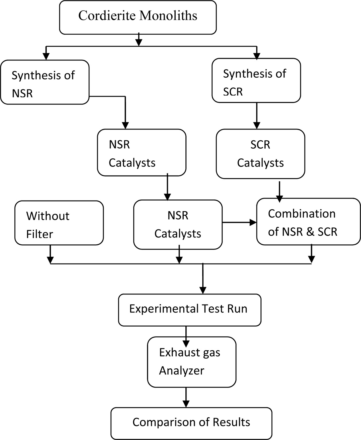
framework with a mix of NSR and SCR technique. The process flow
chart of this work shown in Fig. 1. The diesel engine exhaust
emission has been tested without any filtration aids, with NSR filter and with
NSR and SCR filter along with the preparation of NSR and SCR catalysts.
Finally, the filter capability towards NOx decline is assessed with
different compression ratios and loading conditions.
|
Fig. 1 Process flow chart. |
More toxic substances are there in diesel engine exhaust
emission. Catalytic converters play an important role to minimize such harmful
gases into harmless gases. In this research paper, the synthesis of NSR and SCR
catalysts are explained along with experimental test results.
Materials
and methods used for experimentation
In this experimental research, the cordierite monolith has
been synthesized with suitable catalyst to obtain required NSR
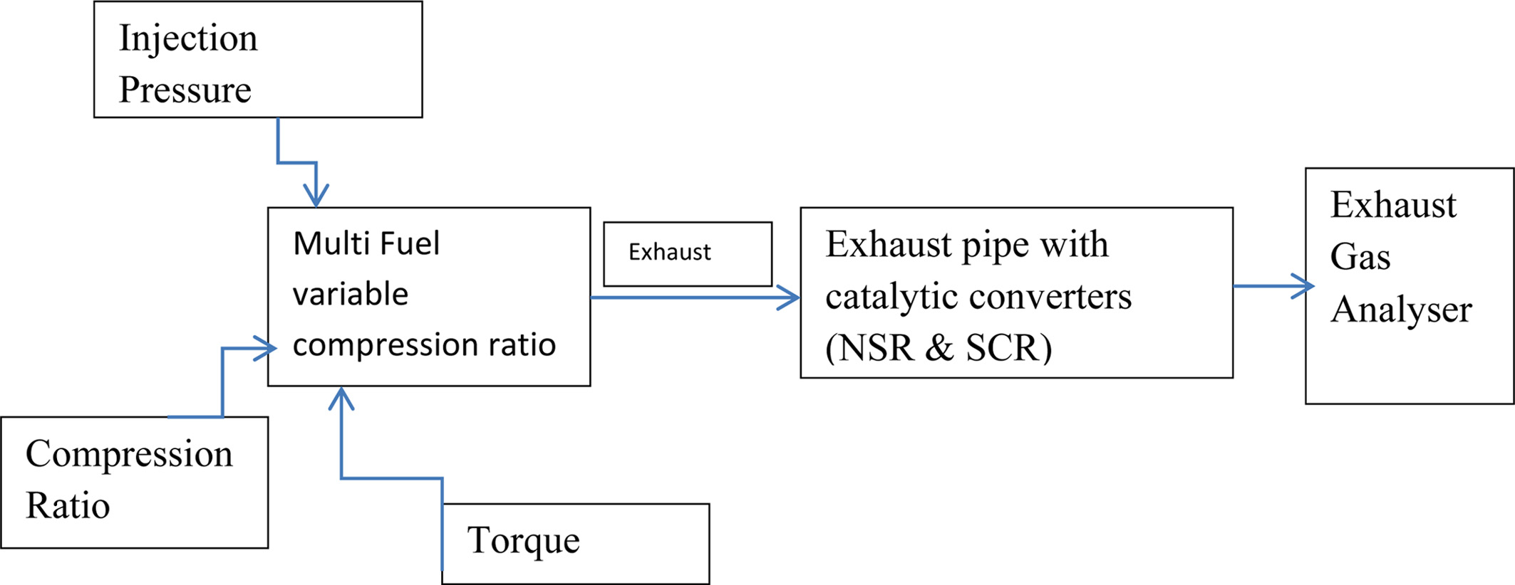
and SCR catalytic converter. A single cylinder diesel engine has been tested
without filter, along with NSR converter, Combination of NSR and SCR
converters. Figure 2 shows the schematic representation
of experimental setup.
Catalytic
converter
In the diesel engine exhaust gas, the harmful gases like
carbon monoxide and unburned hydrocarbon concentrations are more, the catalytic
converters present in the exhaust pipe has oxidized the carbon monoxide,
hydrocarbon emissions into harmless carbon dioxide and water vapour. This was
because of the chemical response of the catalytic converter [28].
Diesel
engine
In this experimentation, single cylinder variable
compression ratio diesel engine was utilized for the testing of catalytic
converters. Diesel is more and more efficient, they should utilize less fuel,
produce less carbon dioxide (CO2) emissions, and contribute less to
global warming [29]
|
Fig. 2 Schematic setup of experimental setup. |
Engine - Single Cylinder Four stroke variable
compression ratio, water cooled
Diesel engine
HP/kW : 5/3.7
RPM : 1500
Bore Diameter : 87.5
mm
Stroke : 110 mm
Compression
Ratio : 17.5
to 20
Injection
pressure : 80-230 bar
Torque : 0-20 Nm
The engine specifications of the Kirloskar engine utilized
in this experimentation are as given above. The four-stroke diesel engine
coupled with eddy current dynamometer for varying load conditions along with
compression proportion of 17.5:1 to 20:1 is taken for testing purposes [30].
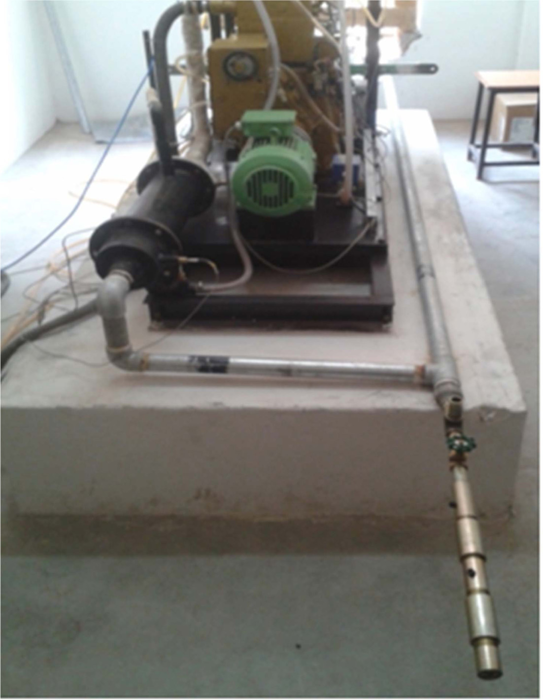
Figure 3, shows the Kirloskar diesel engine along with
loading device of eddy current dynamometer which is used for experimentation. A
piezoelectric transducer part, sensors are associated with the
engine cylinder and crank angle sensor and charge amplifier for
obtaining resolution 1 degree and 5,000 rpm with TDC marker pulse
is mounted to the flywheel and for gaining signals for engine
indication. To measure the percentage of CO, HC, CO2, O2,
and NOx (ppm) emissions the AVL gas analyser has been utilized.
|
Fig. 3 Kirloskar Diesel Engine. |
General
aspects of the NSR (NOx Storage and Reduction) catalysis
NOx storage and reduction is considered as one
of the most promising technology for NOx removal from diesel engine exhausts
gases. It can also be mentioned as Lean NOx Traps (LNT). Recent
excellent reviews can be found in the literature on this technology.
Working:
The NSR catalysts run cyclically under lean environ- ment
(oxidizing) and rich environment (reducing), being defined by
the corresponding Air/Fuel ratios. While running on the road, lean and rich
conditions have to be used in an alternative way. Under lean conditions, with
excess of oxygen i.e.; high (Air/Fuel), NOx are adsorbed (alkaline
or earth-alkaline compounds) by the catalyst, and later under rich conditions
(Air/Fuel < 14.63) the stored NOx are released and reduced. Most
studies in the literature have used storage material as Barium, reduction
material as H-Zeolite.
NSR Mechanism
NSR mechanism can be explained by the five following
steps:
(a) Oxidation of NO to NO2 (lean
conditions, oxidizing environment).
(b) Adsorption of NOx as
nitrites/nitrates on the storage sites (lean period, oxidizing environment).
(c) Injection and evolution of the used reducing
agent (H2, CO or HC).
(d) Release of the stored NOx from the
catalyst surface to the gas stream (rich period, reducing environment).
(e) Reduction of NOx to N2
(rich period, reducing environment).
Procedure for the preparation of catalyst
The procedure for the preparation of NSR catalyst was
detailed below
Wash coat preparation:
This
section focused on the preparation procedure
of monolithic NSR catalyst. In real application, the mechanical properties of
the catalyst temperature and vibrational
strengths may vary due to exhaust gases. Due to high thermal stability and low
expansion coefficient, the Cordierite
(2MgO.2Al2O3.5SiO2), has been chosen as the base material in automotive application.
However, this material exhibits a low
surface area which is not suitable for the subsequent incorporation of the
active phases.
Consequently, the first step of the catalyst preparation
consists of the monolithic substrate wash coating with a high surface area oxide,
usually alumina. The most common wash coating procedure is carried out by
dipping the monolith into slurry, which is usually of alumina. The procedures
are stated below
Step 1:
Calculate the weight of the monolith.
Step 2: Take
100 mL of distilled water and stir using magnetic stirrer.
Step 3: Add
10 g wt.% of γ-Al2O3 and allow it to stir well for 5
min at 450-500 rpm.
Step 4: Add
glacial acetic acid (CH3COOH) gradually and stir
well.
Step 5: Check
the pH level using pH meter. Step 6: Repeat the above step until pH of 2-3 is
obtained.
Step 7: Allow
the solution to stir well for 30 minutes.
Step 8: Dip
the cordierite monolith substrate in the slurry using tongs for 10 seconds.
Step 9: Clear
the pores of the monolith using blower.
Step 10: Dry
it in oven for 20 minutes and allow it to attain room temperature.
Step 11: Again calculate the
weight gained over monolith.
Step 12:
Repeat the steps until required amount of γ-Al2O3 gets
coated over the substrate [31]. It is studied that the threshold value of particle
size around 5 μm which is coincident with the size of the cordierite
macropores; larger alumina particles do not penetrate into the macropores of
the substrate resulting in a poor anchoring of the alumina layer. Therefore,
the smaller the particle size in the slurry, the higher the alumina layer
anchoring [32]. Another characteristic to be controlled is the stabilization of
the alumina slurry so as to avoid the particles from
settling down. It is studied that addition of some acetic acid to
shift pH between 3 and 4 improved the slurry stabilization. Furthermore, the
addition of acetic acid up to 2.5 mol L-1
(pH = 2.6) decreased considerably the viscosity of the slurry, permitting
the use of concentrated Al2O3 slurries without
penalization in the layer homogeneity [31]. Initial weight of the
monolith was 16.9538 g. The weight gained by the
monolith after tenth immersion was 3.9360 g. The amount of γ-alumina loaded to
the monolith depends on the volume of the monolith [31].
Platinum incorporation
The next step in the catalyst preparation is the
incor- poration of the active
phases. As already mentioned, NSR catalysts are usually composed of an alkali
or alkali-earth oxide and a noble metal deposited onto the alumina.
The most common metal used for NSR catalyst formulation
is Pt, whereas BaO is normally used as the storage
component. The order of the incorporation steps of the
active phases Pt and Ba is important, especially when operating at higher
temperatures; a higher storage capacity is obtained when impregnating Pt/Al2O3
with Ba than when impregnating Ba/Al2O3
with Pt, increasing the storage value as much as 54% when adding Ba in the
last step. Platinum can be incorporated following two different
procedures, conventional wetness impregnation and
adsorption from solution. In this work adsorption method was followed due good
compromise between platinum dispersion and thermal stabilization of the catalyst
[31]. In the adsorption procedure, the monoliths were
immersed in an aqueous solution with the adequate
concentration of Pt. The monoliths were maintained immersed in the solution for
24 h so as to reach the adsorption equilibrium. Then, the
monoliths were removed from the solution, the excess of
liquid blown out and finally the monoliths were calcined
at 500 °C, respectively.
Barium incorporation:
The last step in the NSR catalyst preparation is the incorporation
of the NOx storage component, i.e. barium. The
precursor used was barium nitrate and two different procedures
were followed: wetness impregnation and incipient wetness impregnation (also
known as dry impregnation).
In this work wetness impregnation method was adapted;
the monolith channels were filled with an aqueous solution containing the
desired amount of barium. Later the monolith was dried and calcined.
The weight gained by the γ-alumina coated monolith after
ninth immersion was 1.742 g as per requirements [31].
General
aspects of the SCR (Selective Catalytic Reduction) catalysis
The selective catalytic reduction of NOx is
widely used decades before, particularly in stationary applications
like gas turbines, Boilers, power plants etc. Now, SCR is being used in heavy
duty diesel vehicles widely in Europe to meet Euro-4 and later emission
standards.
The SCR consist of monolith similar to that of NSR but the
catalyst used over monolith is a zeolite powder which may be naturally
occurring or synthesized. The reducing agent used is urea/ammonia to convert NOx
into nitrogen (N2) and water vapour (H2O).
Working
The selective catalytic reduction system reduces the NOx
with the help of Metal supported catalyst coated over
wash-coated ceramic monolith. In SCR the catalytic action is
based on the amount of NOx coming from the exhaust of the engine. It
is not working in lean and rich condition as like in NSR. The SCR
consists of monolith coated with metal supported zeolite
catalyst and ammonia tank in which the urea contains 32.5% of ammonia
with de-ionized water.
NO + NO2 + 2NH3 → 2N2
+ 3H2O
SCR Mechanism
a. Dynamic dosage injection of urea based on the NOx
ppm value from the exhaust gas.
b. Reducing the NOx with the
help of NH3 stored inside the zeolite and converts it
into nitrogen and water.
4NH3 + 4NO + O2 → 4N2 +
6H2O
4NH3 + 2NO + 2NO2 → 4N2 +
6H2O
4NH3 + 5O2 → 4NO + 6H2
Catalyst preparation
The catalyst preparation method for ZSM5 & H-Beta SCR
catalyst is same. The H-Beta zeolite is mixed with the copper nitrate with
de-ionized air at 60 oC, for 24 hours for ion exchange. If the
Zeolite is in its NH4-
zeolite form then it is to be calcined at 500 oC, for 4 h [31].
For uniform dispersion of catalyst over the monolith and for
better catalytic action the monolith powder has to be in nano size. For
reducing the size of metal powders the method used is ball milling. The calcined
Cu-Zeolite is mixed with 20% colloidal silica and coated
over the monolith by dip coating. The process is continued
until the monolith had been coated with the required amount of weight
percentage of the Cu-Zeolite catalyst. The following steps were to be carried
out during dip coating for uniform coating of catalyst.
Step 1: The monolith is dipped inside the solution which
was stirred by ultrasonic bath for better particle dispersion.
Step 2: Later water is removed by blowing air using an air
blower inside the monolith.
Step 3: The monolith is now heated inside a furnace at
100 oC for about 15 min to remove the water and make it dry.
Step 4: Once the monolith was dried, it is cooled to room
temperature through natural cooling and weighed to determine the weight gained
for individual iteration.
In this work after fifteenth immersion the weight gained
by the monolith was 1.24 g as the requirement [31].
When the required weight percentage of catalyst has been
loaded over the monolith it is calcined for about 4 hours at
550 oC, for catalyst stabilization on the monolith
and to remove the volatile fractions.
In this research, the proposed design of catalytic
convertor to accommodate both NSR and SCR catalyst has been developed based on
the size of prototype monolith.
Design Constraints:![]() Monolith
size.
Monolith
size.![]() Exhaust
outlet diameter
Exhaust
outlet diameter![]() Flow rate of
gas for the prototype.
Flow rate of
gas for the prototype.![]() Temperature
of exhaust gas.
Temperature
of exhaust gas.![]() Flow
distribution.
Flow
distribution.![]() Catalyst
coating (Wt. %).
Catalyst
coating (Wt. %).
The two catalytic converters NSR and SCR are utilized
for converting dangerous exhaust gases into harmless gases. In order to measure
the required parameters like emission levels and temperatures vent out lets and
thermocouples has provided at the start, in between NSR and SCR catalysts and
at the end. This output taken to the analyser for measurement.
Exhaust
outlet diameter
The exhaust outlet diameter decides the velocity of the
exhaust gas from the engine and it is measured as 1̋ using Vernier calliper.
Flow
rate of gas
The flow rate decides the monolith size to be incor- porated. Monolith is used for the
complete conversion of the exhaust emission. But here, as the monolith size is
constant, the flow rate has been adjusted with respect to the monolith size.
The flow rate of exhaust gas can be calculated theoretically as well as
practically. The practical flow rate can be calculated using an anemom- eter which measures the velocity of
the exhaust gas. Flow rate is the product of exhaust gas velocity and cross
sectional area.
Temperature
of exhaust gas and catalytic converter
The temperature of the exhaust gas decides the conversion
rate of the catalytic converter and the conversion efficiency. Since the
catalytic action is more at elevated temperatures [33], the temperature of the
catalytic converter should be maintained 250 ºC from the beginning in
order to achieve catalytic action at all conditions.
Flow
distribution
Flow distribution refers to the distribution of exhaust
gas throughout the monolith coated with the catalyst for maximum contact of the
exhaust gas with the catalyst. This flow distribution is based on the inlet and
outlet cone angle and at the same time larger cone angles
results in vortex inside the monolith which create
backpressure. So cone angle 45º has been selected.
Thickness
of catalyst
Coating of catalyst over the monolith is based on weight
percentage of monolith’s total weight [31]. If the coating percentage is higher
than the standard value, then the catalyst will block the pores of the
monolith, which will result in high back pressure as well as reduced catalytic
action.
Fabricated
prototype
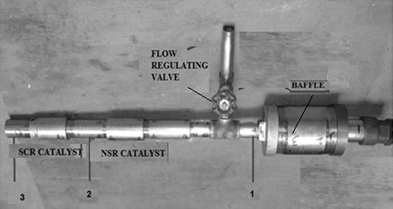
Figure 4 shows the fabricated proto type exhaust pipe to
accommodate the NSR and SCR catalysts. Baffle is located before the location of
the catalysts to direct the flow of exhaust gases. Flow regulating valve also
provided to regulate the quantum of exhaust gas to be entered into the
catalysts section.
|
Fig. 4 Fabricated Exhaust pipe for the placement of NSR and SCR catalysts. |
The testing was done by using diesel as fuel on a
Kirloskar engine that was at 1,500 rpm constant speed engine. The fabricated
proto type exhaust pipe was fitted to the diesel engine fumes with a T-joint.
The testing was completed by applying different load and compression ratio to
find the efficiency of catalytic converters. An eddy current dynamometer [34]
was utilized to load the engine at 0, 50% N-m, and 100% N-m loading conditions.
The testing was done under different laboratory conditions, for example,
shifting temperature and stream rate of exhaust gases. In the running
conditions, diverse info parameters like fuel consumption, indicated power
thermal efficiency etc. also noted at different conditions. The experiment was
conducted at different torques in N-m like 0, 10, 20, and compression ratios
like 17.5, 18.75 and 20. The testing was completed without filter,
with NSR converter, and with NSR-SCR converters. The exhaust emission
gases coming out of the exhaust pipe after catalytic reaction were associated
with the gas analyser and sensors to recognize the percentage
of each gas emitted. The emission performance also tested with the
engine in real-time conditions with the assistance of expert combustion
monitoring systems [35].
In this experimentation, the exhaust gases from a diesel
engine are examined and are classified. For varies compression
ratio (CR), and Torque (L) of the diesel engine, the experimentations are done
without the utilization of filter, with NSR converter, and with NSR and SCR
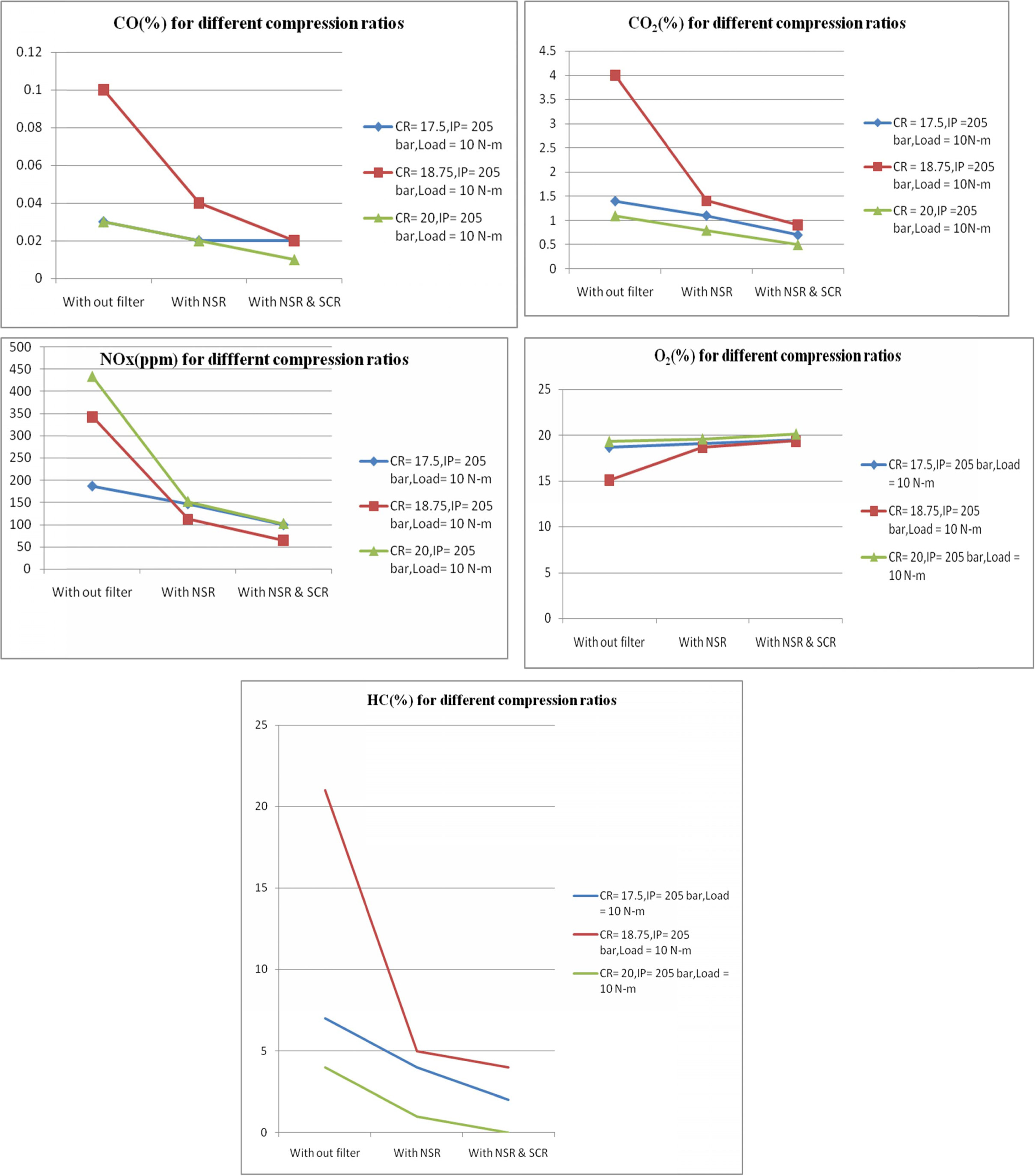
converters. Figure 5, shows the CO, CO2, NOX, O2 and
HC emission values at different output conditions like without
filter, with NSR and with NSR and SCR filters at compression ratios
of 17.5, 18.75 and 20 respectively. When the compression ratio
increases from 17.5 to 20, then the inside pressure of the cylinder increases,
thereby increasing the level of combustion process. This results in increased
CO2 emission and lower CO emission. The NSR and SCR filters also
help to reduce the CO emission up to 200% at higher compression ratios. It is
also observed that the NOx emission increased owing to the higher
pressure inside the cylinder due to high compression ratio. This leads to
increase of heat release rate. The high temperature and pressure
inside the cylinder agitates NOx emissions. Even
though NOx emission was high at high compression
ratio, the percentage of increase of NOx without filter was
132% but after NSR and SCR reaction the percentage of increase
of NOx at high compression ratio was only 20%. This
shows the efficiency of the filters. It is observed that if the
NOx value decreased in the exhaust, it is due to increased O2
emission to the atmosphere. When the compression ratio increases, the flame
propagation is much faster, there by shortening the combustion
process. This increases the charge temperature and reduce the HC
emission to a certain extent. In this work the HC emission is
found to be almost zero at high compression ratios after
NSR and SCR filter reaction process as shown in Fig.
5. However, the CO,CO2 and HC emissions were higher
at compression ratio of 18.75 when com-
pared to compression ratio of 20. Significantly lower O2
emission at this compression ratio indicates that there may be
a chance of incomplete combustion process due to low
cylinder wall temperature, too slow flame speed and in sufficient oxygen
content.
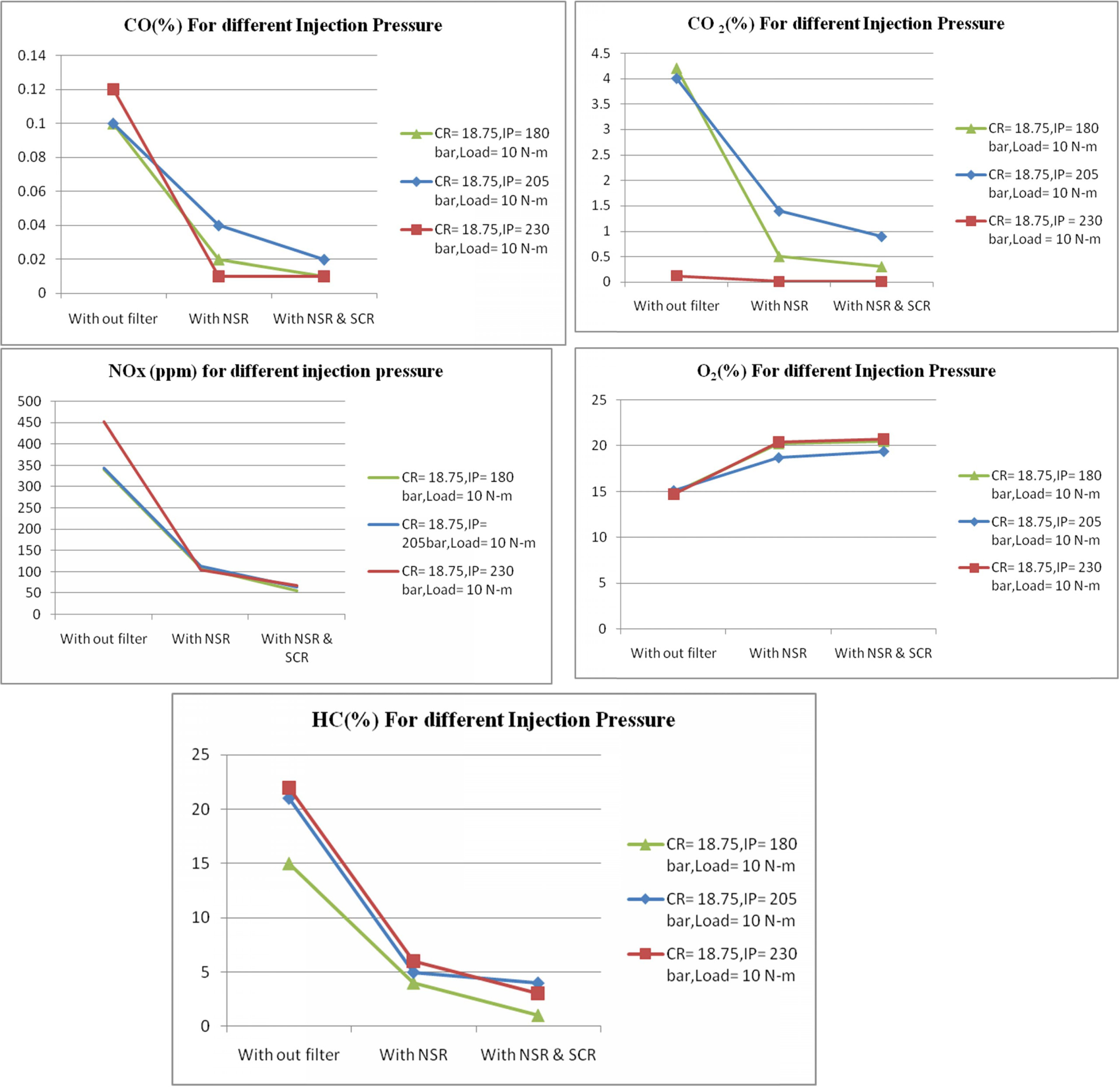
The test was also conducted at different injection
pressures while keeping the compression ratio and load constant.
Spray formation and air-fuel mixing are found to be
influenced by injection pressure. The velocity and momentum of fuel droplets
coming out of the nozzle depends upon the injection pressure.
When the injection pressure is high finer atomization and
better air fuel mixing has been occurring, resulting in high temperature inside
the cylinder. Hence NOx emission increases at high injection
pressure. Figure 6 show the emissions readings at different injection
pressures. It is seen that at 230 bar injection pressure, the NOx
emission reduction is achieved with NSR and SCR filter as 619% compared with no
filter condition. The corresponding CO, CO2 and HC
emissions at various injection pressure are as shown in Fig. 6.
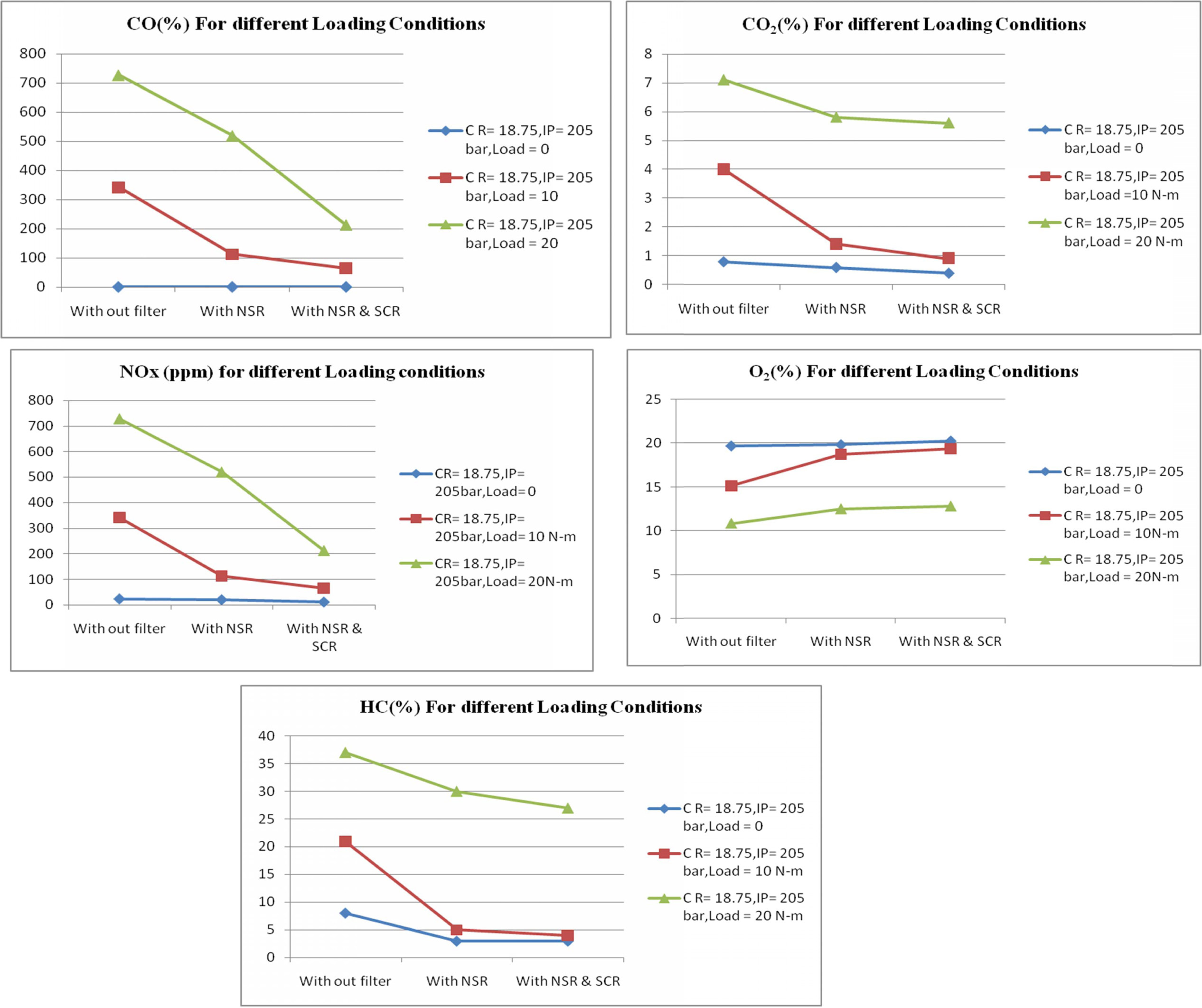
The test was also conducted at different loading
conditions keeping the compression ratio and injection pressure as constant. It
is observed when the load increases the NOx emission also increases
due to high pressure in the air fuel mixture inside the cylinder
Figure 7 show the emission readings at different loading
conditions. At full load condition the NOx emission has been reduced
to 214% when compared with no filter and with NSR and SCR filter.
Proportionately O2 emission also increased noticeably. When the
engine ran at full load condition, the amount of oxygen inside the cylinder was
high but to maintain the constant speed of the engine more fuel is consumed
when compared to no load condition. This may lead to too large diesel droplets
or if insufficient turbulence or swirl is created inside the combustion
chamber, this results in high CO emission at full load condition. But the
percentage of CO emission is found to decreases to 110% while using NSR and SCR
filters compare with no filter at full load conditions. The % HC emission is
compared and shown in Fig. 7.
Comparison of performance
between actual and lab experiments (Table 1).
|
Fig. 5 Emission Readings at different compression ratios. |
|
Fig. 6 Emission readings at different injection pressures. |
|
Fig. 7 Emission Readings at different Loading conditions. |
|
Table 1 Percentage difference of performance between actual and lab experiments. |

This examination can be extended in the future by changing
the selective catalytic reduction system to non-selective catalytic reduction
system, which utilized a precious metal-based catalytic converter. These will
help to reduce the NOx, unburned HC, and CO and these can directly
be connected to IC engines with fuel-rich ignition systems respectively.
The authors gratefully acknowledge the support received
from the Department of Automobile Engineering and Department of Chemistry, PSG
College of Technology, Coimbatore for conducting the experiments.
- 1. B. N. Duncan, L. N. Lamsal, A. M. Thompson, Y.Yoshida, Z. Lu, D. G. Streets, M. M. Hurwitz, and K. E. Pickering, J. Geophys. Res. Atmos. 121 (2015) 976-996.
-

- 2. Z. Liu, H. Su, B. Chen, J. Li, and S. I. Woo, Chem. Eng. J. 299 (2016) 255-262.
-

- 3. W. Xie, Y. Yu, and H. He, J. Environ. Sci. 75 (2019) 396-407.
-

- 4. R. Yang, Y. Cui, Q. Yan Q, C. Zhang, L. Qiu, D. O'Hare, and Q. Wang, Chem. Eng. J. 326 (2017) 656-666.
-

- 5. A. B. López, D. L. Castelló, and J. A. Anderson, Appl. Catal., B. 198 (2016) 189-199.
-

- 6. M. Li, V. G. Easterling, and M. P. Harold, Appl. Catal., B. 184 (2016) 364-380.
-

- 7. A. W. L. Ting, V. Balakotaiah, and M. P. Harold. Chem. Eng. J. 370 (2019) 1493-1510.
-

- 8. I. A. Resitoglu and A. Keskin, Int. J. Hydrogen Energy. 42 (2017) 23389-23394.
-

- 9. D. K. Pappas, T. Boningari, P. Boolchand, and P. G. Smirniotis, J. Catal. 334 (2016) 1-13.
-

- 10. J Han, J. Meeprasert, P. Maitarad, S. Nammuangruk, L. Shi, and D. Zhang, J. Phys. Chem. C. 120 (2016) 1523-1533.
-

- 11. Y. Zheng, D. Luss, and M. P. Harold, SAE Int. J. Engines, 7 (2014) 1280-1289.
-

- 12. J. Barman, S. Arora, R. Khan, and M. Parashar, SAE Technical Paper 1 (2016) 1733.
-

- 13. A. B. López, D. L. Castelló, A. J. McCue, and J. A. Anderson, Appl. Catal., B. 198 (2016) 266-275.
-

- 14. Z. Zhang, B. Chen, X. Wang, L. Xu, C. Au, C. Shi, and M. Crocker, Appl. Catal., B 165 (2015) 232-244.
-

- 15. V. A. Santiago, A. D. Quiñonero, I. S. Basáñez, D. L. Castelló, and A. B. López, Appl. Catal., B. 220 (2018) 524-532.
-

- 16. E. Srinivasa Rao and P. Manohar, J. Ceram. Process. Res. 17 (2016) 448-453.
- 17. F. A. Lafossas, C. Manetas, A. Mohammadi, G. Koltsakis, M. Iida, and K. Yoshida, AIChE J. 63 (2017) 2117-2127.
-

- 18. J. K. Unni, D. Bhatia, V. Dutta, L. M. Das, S Jilakara, and G. P. Subash, SAE Int. J. Engines. 10 (2017) 46-54.
-

- 19. K. Lee and K. W. Nam, J. Ceram. Process. Res. 19 (2018) 54-64.
- 20. X. Yuan, Y. Gao, and X. Wang, Int. J. Engine Res. 17 (2016) 169-178.
-

- 21. M. Han and B. Lee, Int. J. Automot. Technol. 16 (2015) 371-378.
-

- 22. J. S. Park, J. G. Yeo, S. C. Yang, and C. H. Cho, J. Ceram. Process. Res. 19 (2018) 20-24.
- 23. H. Gu, K. M. Chun, and S. Song, Int. J. Hydrogen Energy. 40 (2015) 9602-9610.
-

- 24. X. Cheng, D. Su, Z. Wang, C. Ma, and M. Wang, Int. J. Hydrogen Energy. 43 (2018) 21969-21981.
-

- 25. I. A. Resitoglu, A. Keskin, H. Özarslan, and H. Bulut, Int. J. Environ. Sci. Technol. 16 (2019) 6959-6966.
-

- 26. U. De-La-Torre, B. Pereda-Ayo, M. Moliner, and A. Corma, Appl. Catal., B 187 (2016) 419-4.
-

- 27. E. R. Rangel, J Ceram. Process. Res. 9 (2008) 61-63.
- 28. I. Cornejo, P. Nikrityuk, and R. E. Hayes, Chem. Eng. Sci. 175 (2018) 377-386.
-

- 29. C. P. Cho, Y. D. Pyo, J. Y. Jang, G. C. Kim, and Y. J. Shin, Appl. Therm. Eng. 110 (2017) 18-24.
-

- 30. P. Baskar, and A. Senthilkumar, Eng. Sci. Technol. 19 (2016) 438-443.
-

- 31. B. Pereda-Ayo, R. López-Fonseca, and J. R. González-Velasco, Appl. Catal., A. 363 (2009) 73-80.
-

- 32. C. Agrafioti and, A. Tsetsekou, J. Eur. Ceram. Soc. 20 (2000) 815-824.
-

- 33. B. Pereda-Ayo, D. Duraiswami, J. A. González-Marcos, and J. R. González-Velasco, Chem. Eng. J. 169 (2011) 58-67.
-

- 34. S. P. Venkatesan and P. N. Kadiresh, Int. J. Ambient Energy. 37 (2016) 64-67.
-

- 35. S. Yuvaraj, K. M. Kiran Babu, P. Kaleeshwaran, and S. Tamilselvan, Lecture Notes in Mechanical Engineering. Springer, Singapore, (2017) 231-238.
-

 This Article
-
2019; 20(6): 621-631
Published on Dec 31, 2019
- 10.36410/jcpr.2019.20.6.621
- Received on Oct 10, 2019
- Revised on Oct 22, 2019
- Accepted on Oct 28, 2019
 Services
- Abstract
introduction
literature review
proposed research work
experimental setup and design
engine specification
nox storage and reduction & s elective catalytic converter
design and fabrication of reactor prototype
experimental procedure
results and discussion
conclusion
- Acknowledgements
- References
- Full Text PDF
Shared
 Correspondence to
- Rekha Durairaj
-
Department of Automobile Engineering, PSG College of Technology, Coimbatore, TN 641004, India
Tel : +919994367552 Fax: +04222573833 - E-mail: reksun02@gmail.com


 Copyright 2019 International Orgranization for Ceramic Processing. All rights reserved.