- Mechanical properties and radiation shielding performance in concrete with electric arc furnace oxidizing slag aggregate
Hee Seob Lima, Han Seung Leeb and Seung Jun Kwona,*
aDepartment of Civil Engineering, Hannam University, 70 Hannam-ro, Daedeok-gu, Daejeon, 34430, Korea
bDepartment of Architecture Engineering, Hanyang University-ERICA, Ansan 15588, Korea
In this study, physical properties of normal concrete, magnetite concrete, EAF concrete, and EAF concrete with added iron powder were evaluated and a feasibility of radiation shielding is also evaluated through irradiation tests against X-rays and gamma-rays. While the unit weight of EAF concrete (3.21 t/m3) appeared lower than that of magnetite concrete (3.50 t/m3), the results in compressive strength of EAF concrete were greater than those in magnetite and normal concrete. While the radiation transmission rate of normal concrete reaches 26.0% in the X-ray irradiation test, only 6.0% and 9.0% of transmission rate were observed in magnetite concrete and linear relationship with unit volume weight and radiation shielding. In the gamma-ray irradiation test, the performance of EAF and magnetite concretes appeared to be similar. Through the results on the excellent physical properties and radiation shielding performance a potential applicability of EAF concrete to radiation shielding was verified.
Keywords: Electric arc furnace oxidizing slag, Concrete, Radiation shielding concrete, Magnetite, X-ray, Gamma-ray
Radiation shielding concretes are commonly used in nuclear power plants, nuclear medicine facilities, and nuclear research facilities [1, 2]. With respect to the material for production of radiation shielding concretes, that magnetite, barite, and hematite in high ratios and colemanite and boron additives in low ratios should be used as the materials for the production of radiation shielding concretes [3-10]. While materials with high-specific gravity are required for the shielding of gamma rays, materials such as water, boron, and graphite can be used for neutron radiation [11]. The radiation shielding property varies with the amount and type of concrete aggregates.
The ACI 304.3R9 report shows that heavy aggregate can be less fluid when mixed with concrete due to its irregular shape and higher acute angle compared to ordinary aggregate [12]. Also, it was pointed out that the possibility of segregation the concrete is high due to the high density of the heavy aggregate. Various materials have been used in previous studies to alleviate these issues and develop radiation shielding concrete. For example, research has been conducted on the development of concrete based on radiation shielding materials such as lead and iron. The gamma-ray of concrete contained lead additive were investigated and the gamma shielding properties were improved [13]. Fiber reinforced concrete containing steel fiber and lead fiber has improved radiation shielding properties [14]. In addition, there have been studies on the calculation of radiation attenuation coefficients in Portland cements mixed with silica fume, blast furnace slag and natural zeolite [15], and a study on the development of radiation shielding concrete based on the aggregates specific to each nation (e.g., stones or soil) [16-18]. The studies on the mass attenuation coefficients of building materials (glass, concrete, marble, fly ash, cement) according to energy range (10 keV ~ 100 GeV) have also been carried out [19]. A few recent studies have focused on steel industry by-products [20-22]. Although these by-products contain a large amount of recyclable and useful resources, current measures of disposal rely primarily on depositing them into landfills. With global attention to environmental problems, the practical applicability of industrial by-products is being researched. Among steel slags, extensive research has been conducted on the recyclability of electric arc furnace oxidizing slag(EAF) [23-27]. J. T. San-Jose examined the mechanical performance of concrete using two types of EAF. As a result of the verification, the effect of increasing the compressive strength was remarkable, and the evaluation of the physical performance of the aggregate explains the sufficient possibility as an alternative to the aggregate of the concrete [28].
A. Santamaria verified the mechanical performance of concrete by controlling the mixing of EAF. It was pointed out that the particle size distribution of the aggregate by the crushing process through the generation of the EAF was uneven and the quality performance was verified [29].
F. Faleschini has shown that it has superior performance to general concrete in the Interfacial transition zone (ITZ) of EAF concrete. The applicability of EAF as high strength concrete was also investigated. It is possible to produce high-strength concrete without inorganic additives, and it is suitable for high-density concrete applications [30, 31].
EAF contains iron (15 ~ 30%), and has a high density of 3.0 ~ 3.7 t/m3. Therefore, it is believed that such high-density EAF can be used as an aggregate for radiation shielding concrete.
In this study, the possibility of developing a radiation shielding concrete through radiation shielding test of magnetite-based concrete and EAF concrete was verified by reviewing the physical and chemical properties of EAF, which is an industrial byproduct, and assess the radiation shielding performance of concretes based on each material through X-ray and gamma-ray irradiation experiments.
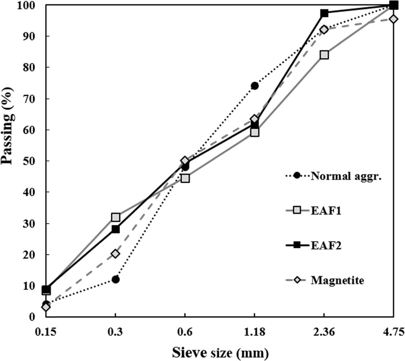
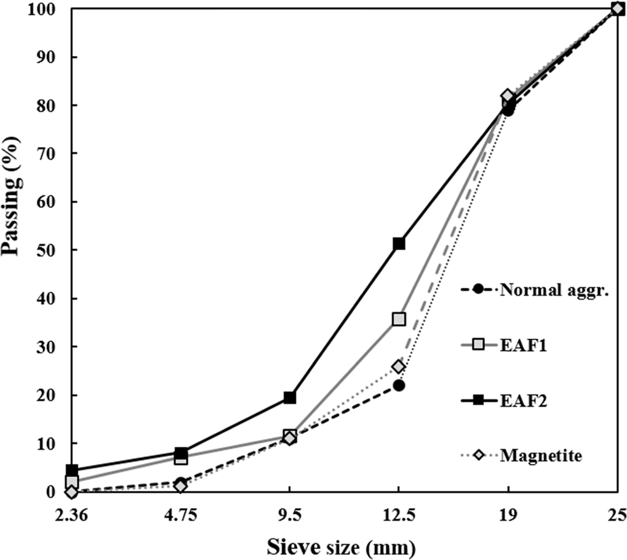
Ordinary Portland cement (OPC), specified by ASTM C 150-05 (Standard specification for Portland cement), was used. EAFs have varying density depending on the steelmaking process. The unit volume weights of EAF1 and EAF2 are 3.7 t/m3 and 3.4 t/m3, respectively. The density of magnetite is over 4.3 t/m3, and its fitness modulus (FM) was adjusted discretionarily to suffice for its use as a concrete aggregate during the experiment. Figs. 1 and 2 show the grading curves for aggregates.
In this study, iron powder was mixed with EAF to improve unit volume weight. The iron powder was generated as an industrial byproduct of the steelmaking process. Iron powder has a high density of around 7.2 t/m3, and comprises more than 90% Fe2O3.
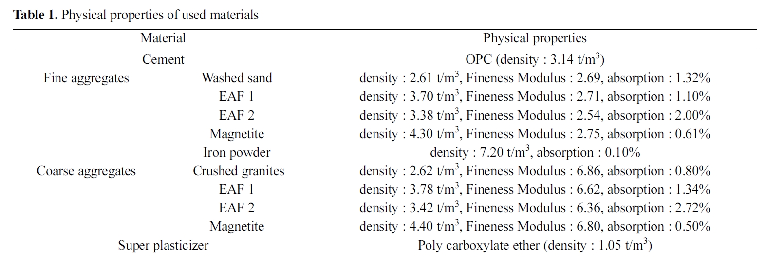
Normal aggregates, EAF, magnetite, and iron powder were used, and experiments were conducted to measure the physical properties of the aggregates that were specified by ASTM C 33/C33M-08 (Standard specification for concrete aggregates), ASTM C 29 (Standard test method for bulk density and voids in aggregate), ASTM C 127-15 (Standard test method for relative density and absorption of coarse aggregate), ASTM C 128-15 (Standard test method for relative density and absorption of fine aggregate), and ASTM C 136 (Standard test method for sieve analysis of fine and coarse aggregates). Table 1 shows the physical properties of the used materials.
Table 2 shows the chemical properties of each material determined by XRF analysis. The heavy aggregate contains various types of chemical components in the form of oxides. EAF aggregate contains about 35% of Fe2O3, which affects radiation shielding, and about 25% of CaO. The magnetite aggregate also contains about 58% of Fe2O3 and shows high density. Therefore, it is considered that heavy aggregate is basically effective for radiation shielding compared with general aggregate.
|
Fig. 1 Grading curves for fine aggregates (ASTM C 136). |
|
Fig. 2 Grading curves for coarse aggregates (ASTM C 136). |

|
Fig. 3 Experimental configuration for X-ray attenuation measurements. |
|
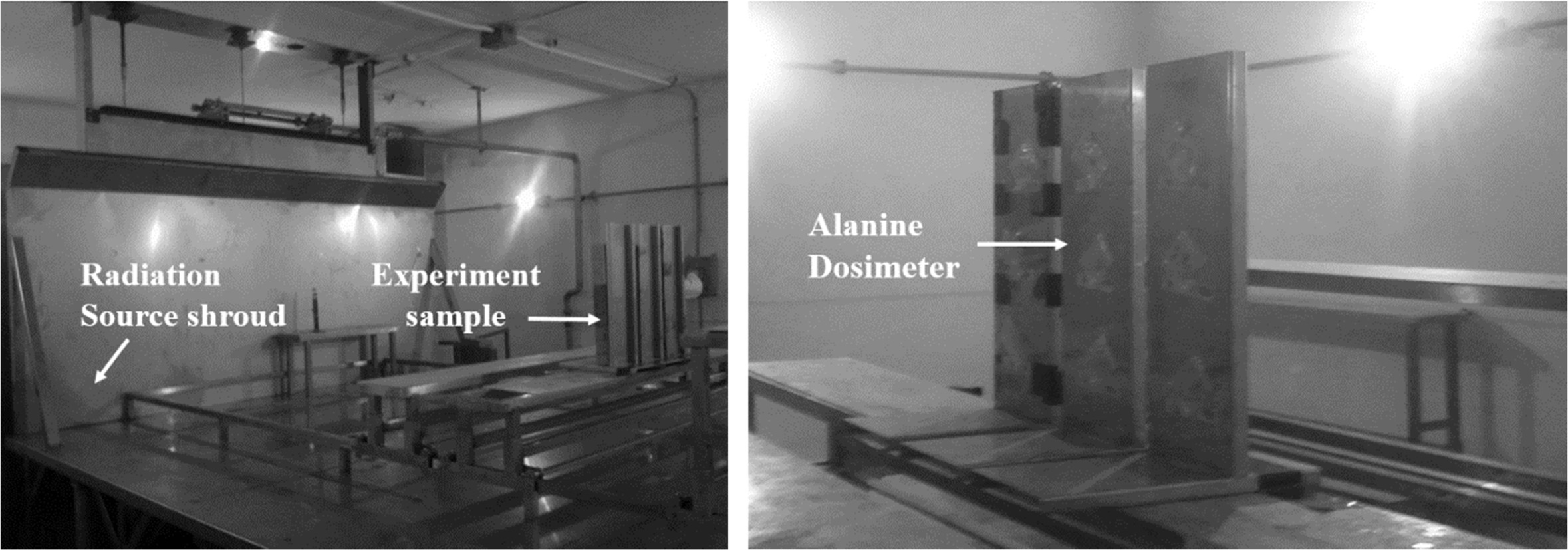
Fig. 4 Experimental configuration for gamma-ray attenuation measurements. |
|
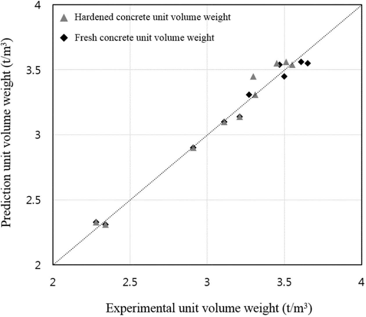
Fig. 5 Compare the experimental unit volume weight with the predicted unit volume weight. |
|
Fig. 6 Test results of compressive strength. |
|
Fig. 7 Test results of unit volume weight and compressive strength. |
|
Fig. 8 Exp Response for X-ray of specific channels. |
|
Fig. 9 Transmission rate/linear attenuation coefficient against the unit volume weight. |
|
Fig. 10 The estimation of concrete thickness to gamma-ray shielding rate. |
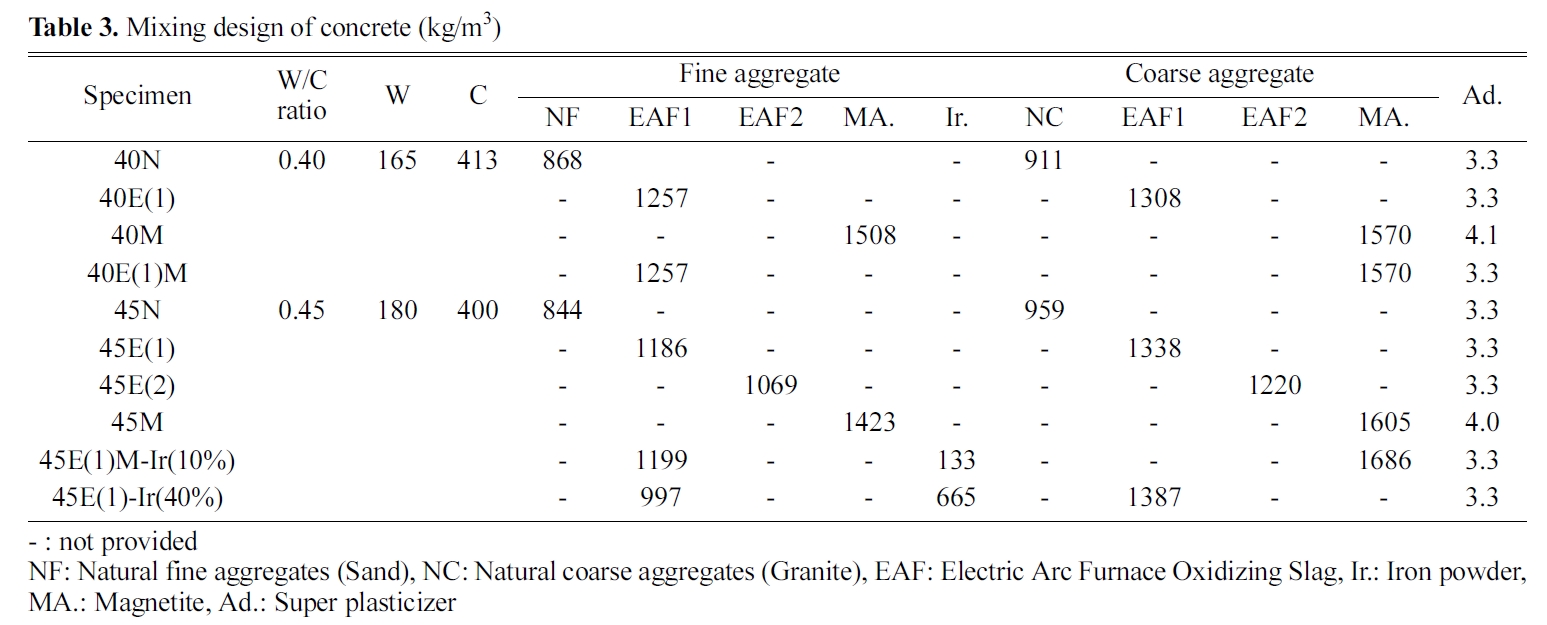
Table 3 shows the mix design of concrete. The mix design of concrete was based on water/cement (W/C) ratios of 0.4 and 0.45. EAF aggregate was used 2 type with different physical properties (EAF1, EAF2). Table 4 shows the description of the symbols of the specimen. Experiments were conducted on mechanical performance of concrete and radiation shielding performance test. For fresh concrete, the air content and unit volume weight were measured using ASTM C 173 (Standard test method for air content of freshly mixed concrete by the volumetric method), and a slump test was conducted using ASTM C 143 (Standard test method for slump of hydraulic-cement concrete). With hardened concrete, ASTM C 39 (Standard test method for compressive strength of cylindrical concrete specimens) compressive strength tests, X-ray irradiation experiments, and gamma-ray irradiation experiments were conducted.
The compressive strength test of hardened concrete was calculated as the average of three cylinder specimens of dimensions Ø10 ×20 cm after standard curing for 3, 7, and 28 days. The specimens for X-ray and gamma-ray irradiation experiments had dimensions of 13.6 cm×16 cm×5 cm.
Fig. 3 shows the X-ray irradiation experiment. The X-ray from the X-ray generator is attenuated by each specimen, and the dosage is calculated using the LaBr3(Ce) detector. The distance between the X-ray generator and the specimen was kept constant at 1 m for all specimens, and the thickness of all the specimens was 5 cm. The X-ray spectrum was generated at a voltage of 150 kVp. Table 5 shows the description of the X-ray generator.
Fig. 4 shows the high-intensity gamma-ray irradiation device used for the gamma-ray irradiation experiment, and 1.33 MeV gamma-rays emitted from a Co-60 radioactive isotope were used. Specimens identical to those used in the X-ray irradiation experiment were used, and the absorbed radiation dose was measured by analyzing the chemical change through chemical dosimetry. An alanine dosimeter was used in this study, which generates free radicals when it absorbs radiation, allowing the measurement of radiation dose using electron paramagnetic resonance (EPR).
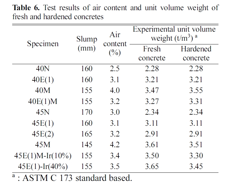
Experimental results, including air content, unit volume weight, compressive strength, and slump test of each specimen, are shown in Table 6. The slump was found to be around 150 ± 25 mm. The air contents results, highest air contents of more than 4.0% were observed for 40M and 45M. The unit volume weight experiment results revealed 3.11 ~ 3.21 t/m3 of EAF1 concrete, 2.91 t/m3 of EAF2 concrete, 3.51 ~ 3.55 t/m3 of magnetite concrete, 3.31 t/m3 of 40E(1)M, 3.30 t/m3 of 45E(1)M(Ir10%), 3.45 t/m3 of 45E(1)(Ir40%), and 2.28-2.34 t/m3 of normal concrete. W/C change did not entail any change in the unit volume weight and each specimen show differences with aggregates.
Fig. 5 shows a comparison of the predicted and measured unit volume weights of fresh and hardened concretes. Comparing the unit volume weights of concrete before and after hardening, at a W/C ratio of 0.45, the unit volume weights of 45M, 45E(1)M-Ir(10%), and 45E(1)-Ir(40%) appeared to decrease. It was observed that this difference occurs when the unit volume weight exceeds 3.50 t/m3. In the case of iron powder substituted concrete, the unit volume weights decreased significantly.
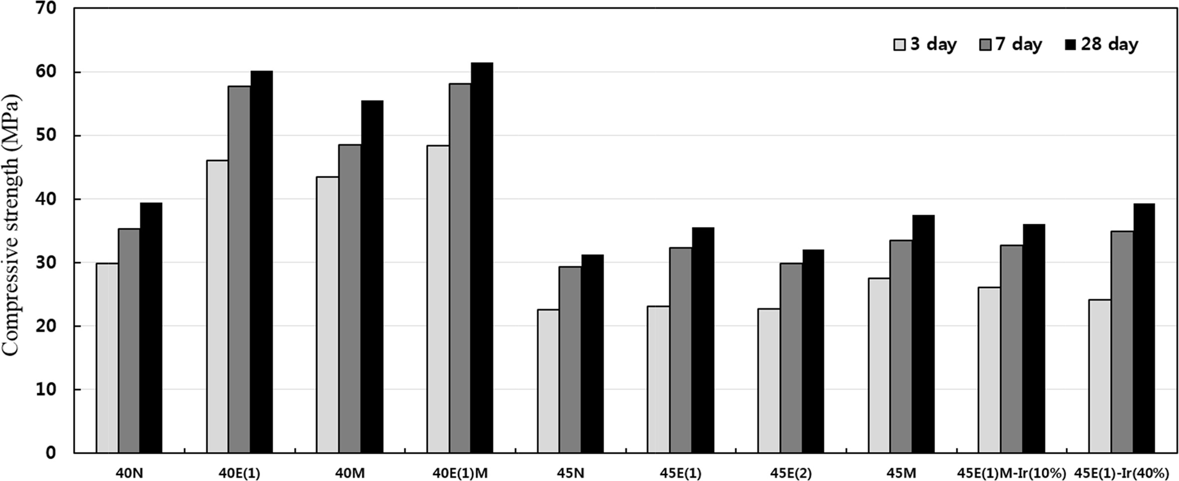
Fig. 6 shows a comparison of the test results of compressive strength. In the compressive strength test results of W/C ratio of 0.40, 40N exhibited the lowest compressive strength of 39.5 MPa. 40E(1) had a compressive strength of 60.2 MPa, and 40E(1)M showed the highest compressive strength of 61.5 MPa. EAF concrete demonstrated 20MPa higher compared to normal concrete. At W/C ratio of 0.45, it resulted in 39.3 MPa which is the highest in 45E(1)-Ir(40%). In contrary, 45N was shown as the lowest at 31.2 MPa.
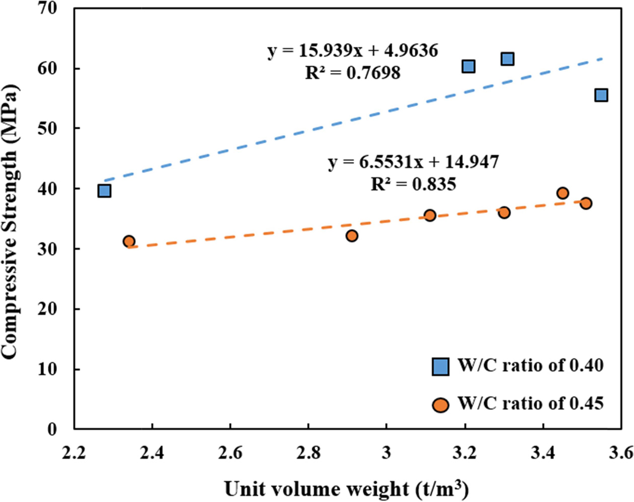
Fig. 7 shows the experimental results for the unit volume weight and compressive strength of hardened concrete. Comparing the unit volume weights and compressive strengths of each specimen, it was found that the compressive strength increases with unit volume weight. However, when the unit volume weight was greater than 3.50 t/m3, a decrease in strength was also observed. While the unit volume weight of 40M was the highest at 3.55 t/m3, its compressive strength was lower than that of 40E(1). Moreover, the sample with at W/C ratio of 0.45, 45M was the highest at 3.51 t/m3, its compressive strength was lower than that of 45E(1)Ir(40%). It is considered by increasing the capacity of the admixture used rather than is not the effect of increasing the compressive strength due to the increase of the unit volume weight. Previous researchers have shown that EAF aggregate has the effect of increasing compressive strength when used as concrete [32, 33]. In addition, the compressive strength enhance- ment effect occurred in the magnetite concrete is judged to be the shape of the magnetite. This suggests that the adhesion between the magnetite and the paste is improved. Therefore, it was confirmed that the concrete strength can be controlled by changing the aggregate. The compressive strength of concrete is determined by the adhesion of the paste to the surface roughness of the aggregate rather than the chemical composition of the aggregate.
|
Table 6 Test results of air content and unit volume weight of fresh and hardened concretes |
The fundamental equation for the X-ray irradiation experiment is Eq. (1). Assume that the X-ray irradiating upon the shield has an intensity of I0, while that after the irradiation can be denoted as I. Here, x is the thickness of the shield, and µt is the linear attenuation coefficient, which represents the probability of the X-ray causing an arbitrary interaction with the material per unit length. Linear attenuation coefficient can be described using the Lambert law.

Here, I = dose rate at the surface of the shield facing towards the X-ray source
I0 = dose rate at the surface of the shield opposite to the X-ray source
μt = linear attenuation coefficient, which is a constant representing the X-ray absorption ratio of the shielding material.
x = thickness of the shield
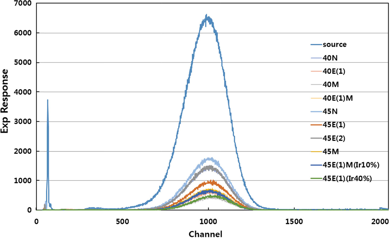
Fig. 8 shows the Exp Response for X-ray of specific channels. The spectrum data of the source appears as the total number of data read by the detector on a particular channel. The spectrum data of the concretes using each material represents the X-ray transmission performance of the irradiated materials, with lower values of the Exp response of channel implying better shielding performance. The value of the data was the lowest at 40M, and the highest at 40N.
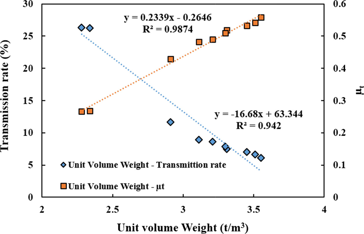
Table 5 shows the test results from the X-ray irradiation. From the X-ray irradiation experiment, normal concrete specimens, 40N and 45N, showed a transmission rate of around 26%; EAF concretes, 40E(1), 45E(1), showed a transmission rate of around 9%; 12% of 45E(2). EAF concretes containing iron powder, 45E(1)M-Ir(10%), 45E(1)-Ir(40%) had a transmission rate of 6.99 ~ 7.82%; and magnetite concretes, 40M and 45M, showed a transmission rate of 6.14 ~ 6.66%. Equivalent transmission effects are observed in magnetite concrete, and in 45E(1)M-Ir(10%) and 45E(1)-Ir(40%), of which the unit volume weight was discretionarily increased.
In order to compare the shielding properties of the concrete, the half value layer(HVL) was calculated to be 2.6 cm for normal concrete and 1.35 cm for EAF concrete, and the difference is about 1.25 cm. In addition, it was confirmed that the maximum difference between general concrete and magnetite concrete is about 1.36 cm.
Fig. 9 shows the transmission rate/linear attenuation coefficient against the unit volume weight. It can be seen that the linear attenuation coefficient increases with unit volume weight, and the correlation of the decrease in transmission rate with increasing unit volume weight is shown.
The experimental results for the γ-ray irradiation experiment were obtained from chemical dosimetry using a γ-ray irradiation device. Table 6 shows the radiation dose and the transmission rate measured after γ-ray irradiation. While no significant difference can be observed in the transmission rate of each concrete due to the high penetration ratio of γ-rays, it can be observed that the γ-ray transmission rate decreases with unit volume weight, with a trend similar to the case for X-ray irradiation.
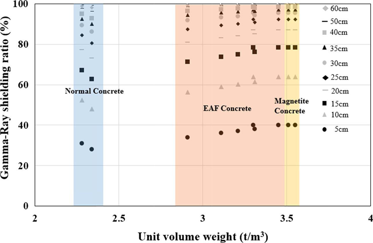
Fig. 10 shows the estimates the thickness of concrete assuming the gamma-ray shielding rate. The shielding ratio is up to 40% for a thickness of 5 cm. Normal concretes (40N, 45N) show a 99% shielding ratio at a thickness of around 600 mm. EAF concretes (40E(1), 45E(1)) show a stable shielding ratio in 45 ~ 50 cm of thickness range. Not only EAF concretes with steel powder (45E(1)M-Ir(10%), 45E(1)-Ir(40%)) but also magnetite concretes (40M, 45M) show a stable shielding ratio at a thickness of 40 ~ 45 cm.
From the present work, the following results were obtained for the applicability of EAF as a radiation shielding concrete.
1. EAF concrete showed a higher compressive strength and improved workability than magnetite concrete. The effect of unit weight on strength development seems to be small compared with the effect of replacement of EAF aggregate. The compressive strength of concrete is more affected by the adhesion of the cement paste to the surface of aggregate than the chemical properties of the aggregate.
2. From the X-ray irradiation experiment, the shielding ratios of normal concrete, EAF1 concrete, EAF2 concrete, EAF with iron powder concrete, and magnetite concrete were evaluated to be about 26.0%, 9.0%, 12.0%, 7.0%, and 6.0% respectively, which indicates a linear relationship between unit volume weight and linear attenuation coefficient.
3. In terms of γ-ray shielding ratio, 99% shielding ratio was evaluated from normal concretes with a thickness of 600 mm. EAF concretes (40E(1) and 45E(1)) showed a stable shielding ratio in 45 ~ 50 cm of thickness range. Not only EAF concretes with steel powder (45E(1)M-Ir(10%), 45E(1)-Ir(40%)) but also magnetite concretes (40M, 45M) showed a stable shielding ratio at a thickness of 40 ~ 45 cm.
4. Comparing the X-ray and γ-ray shielding ratios, similar linear relationships in EAF concrete were observed as those in magnetite concrete, which reveals that EAF concrete can be utilized a radiation shielding concrete with improved strength and workability.
5. The major problem of magnetite concrete is reported to be segregation of aggregates due to heavy self-weigh When EAF concrete is employed for radioprotection against X-ray and γ-ray, it can provide more reduced thickness than OPC concrete and more reasonable workability than magnetite concrete with eco-friendly manner.
6. Although the density of concrete is important in shielding radiation, abundant amount of Fe2O3 in EAF aggregate on radiation shielding.
This research was supported by Basic Science Research Program through the National Research Foundation of Korea (NRF) funded by the Ministry of Science, ICT & Future Planning (No.2015R1A5A1037548)
- 1. O. Gencel, Fire. Mater. 36[3] (2012) 217-230.
-

- 2. A.M. El-Khayatt, Ann. Nucl. Energy. 37[7] (2010) 991-995.
-

- 3. I. Akkurt, C. Basyigit, S. Kilincarslan, and B. Mavi, Prog. Nucl. Energy. 46[1] (2005) 1-11.
-

- 4. I. Akkurt, C. Basyigit, S. Kilincarslan, B. Mavi and A. Akkurt, Cem. Concr. Compos. 28[2] (2006) 153-157.
-

- 5. I. Akkurt, H. Akyildirim, B. Mavi, S. Kilincarslan, C. Basyigit, Ann. Nucl. Energy. 37[7] (2010) 910-914.
-

- 6. I. Akkurt, H. Akyildirim, B. Mavi, S. Kilincarslan, C. Basyigit, Prog. Nucl. Energy. 52[7] (2010) 620-623.
-

- 7. M.H. Kharita, M. Takeyeddin, M. Alnassar, S. Yousef, Prog. Nucl. Energy. 50[1] (2008) 33-36.
-

- 8. A. Mesbahi, A.A. Azarpeyvand, A. Shirazi, Ann. Nucl. Energy. 38[12] (2011) 2752-2756.
-

- 9. A.E.S. Abdo, M.A.M. Ali, M.R. Ismail, Ann. Nucl. Energy. 30[4] (2003) 391-403.
-

- 10. O. Gencel, F. Koksal, C. Ozel, W. Brostow, Constr. Build. Mater. 29 2012) 633-640.
-

- 11. S. Xu, M. Bourham, A. Rabiei, Mater. Des. 31[4] (2010) 2140-2146.
-

- 12. ACI 304.3R-96. ACI Committee Report (1996) 1-8.
- 13. D.R. Ochbelagh, S. Azimkhani, H.G. Mosavinejad, Nucl. Eng. Des. 241[6] (2011) 2359-2363.
-

- 14. A. Sharma, G.R. Reddy, L. Varshney, H. Bharathkumar, K.K. Vaze, A.K. Ghosh, H.S. Kushwaha, T.S. Krishnamoorthy, Nucl. Eng. Des. 239[7] (2009) 1180-1185.
-

- 15. I. Turkmen, Y. Ozdemir, M. Kurudirek, F. Demir, O. Simsek, R. Demirboga, Ann. Nucl. Energy. 35[10] (2008) 1937-1943.
-

- 16. M.N. Alam, M.M.H. Miah, M.I. Chowdhury, M. Kamal, S. Ghose, R. Rahman, Appl. Radiat. Isot. 54[6] (2001) 973-976.
-

- 17. I.C.P. Salinas, C.C. Conti, R.T. Lopes, Appl. Radiat. Isot. 64[1] (2006) 13-18.
-

- 18. M.E. Medhat, Ann. Nucl. Energy. 36[6] (2009) 849-852.
-

- 19. C. Singh, T. Singh, A. Kumar, G.S. Mudahar, Ann. Nucl. Energy. 31[10] (2004) 1199-1205.
-

- 20. M. Maslehuddin, A.A. Naqvi, M. Ibrahim, Z. Kalakada, Ann. Nucl. Energy. 53 (2013) 192-196.
-

- 21. N. Saca, L. Radu, V. Fugaru, M. Gheorghe, I. Petre, J. Clean. Prod. 179 (2018) 255-265.
-

- 22. M. Papachristoforou, and I. Papayianni, Radiat. Phys. Chem. 149 (2018) 26-32.
-

- 23. G. Salihoglu, and V. Pinarli, J. Hazard. Mater. 153[3] (2008) 1110-1116.
-

- 24. G. Wang, Y. Wang, Z. Gao, J. Hazard. Mater. 184 (2010) 555-560.
-

- 25. G. Wang, Constr. Build. Mater. 24[10] (2010) 1961-1966.
-

- 26. G. Adegoloye, A.L. Beaucour, S. Ortola, A. Noumowe, Constr. Build. Mater. 76 (2015) 313-321.
-

- 27. N.H. Roslan, M. Ismail, Z. Abdul-Majid, S. Ghoreishiamiri, B. Muhammad, Constr. Build. Mater. 104 (2016) 16-24.
-

- 28. J.T. San-Jose, I. Vegas, I. Arribas, I. Marcos, Mater. Des. 60 (2014) 612-619.
-

- 29. A. Santamaria, A. Orbe, M.M. Losanez, M. Skaf, V. Ortega-Lopez, J.J. Gonzalez, Mater. Des. 115 (2017) 179-193.
-

- 30. F. Faleschini, K. Brunelli, M.A. Zanini, M. Dabala, C. Pellegrino, J. Sustain. Metall. 2[1] (2016) 44-50.
-

- 31. F. Faleschini, M.A. Fernandez-Ruiz, M.A. Zanini, K. Brunelli, C. Pellegrino, E. Hernandez-Montes, Constr. Build. Mater. 101 (2015) 113-121.
-

- 32. N. Faraone, G. Tonello, E. Furlani, S. Maschio, Chemosphere. 77[8] (2009) 1152-1156.
-

- 33. H. Qasrawi, F. Shalabi, I. Asi, Constr. Build. Mater. 23[2] (2009) 1118-1125.
-

 This Article
-
2019; 20(4): 363-371
Published on Aug 31, 2019
- Received on Feb 15, 2019
- Revised on Jul 16, 2019
- Accepted on Jul 24, 2019
 Services
- Abstract
introduction
experimental
results and discussion
conclusions
- Acknowledgements
- References
- Full Text PDF
Shared
 Correspondence to
- Seung Jun Kwon
-
Department of Civil Engineering, Hannam University, 70 Hannam-ro, Daedeok-gu, Daejeon, 34430, Korea
Tel : +82-42-629-8020
Fax: +82-42-629-8366 - E-mail: jjuni98@hannam.ac.kr





 Copyright 2019 International Orgranization for Ceramic Processing. All rights reserved.